


There are several state-of-the-art test rigs and facilities at NASA’s Glenn Research Center in Cleveland that are operated by the center’s mTRAX Planetary Exploration team. These rigs serve to test planetary roving vehicle systems and components in simulated planetary and lunar conditions.
Facility Overview
There are several state-of-the-art test rigs and facilities at NASA’s Glenn Research Center in Cleveland that are operated by the center’s mTRAX Planetary Exploration team. Most of the facilities are located in the Engine Research Building. These rigs serve to test planetary roving vehicle systems and components in simulated planetary and lunar conditions. Most of the test capabilities are focused on the interactions between rover components (such as tires and excavation tools) and the terrain, though there are environmental test capabilities as well. A few examples of ongoing research in these labs include conducting full-scale vehicle mobility tests to determine new methods for traversing challenging terrain, evaluating the performance of novel rover tires in lunar and Martian environments, and testing various excavation techniques for digging on the Moon.
Capabilities
The following test rigs and facilities fall under the mTRAX Planetary Exploration umbrella:
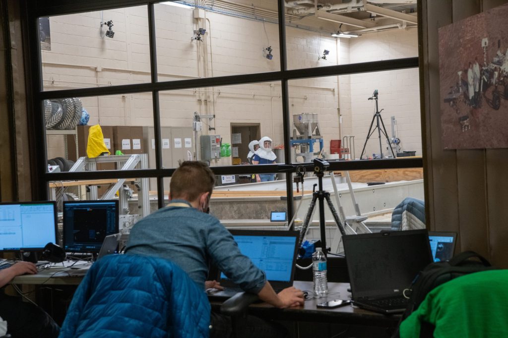
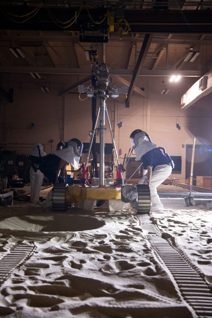
Simulated Lunar Operations (SLOPE) Laboratory
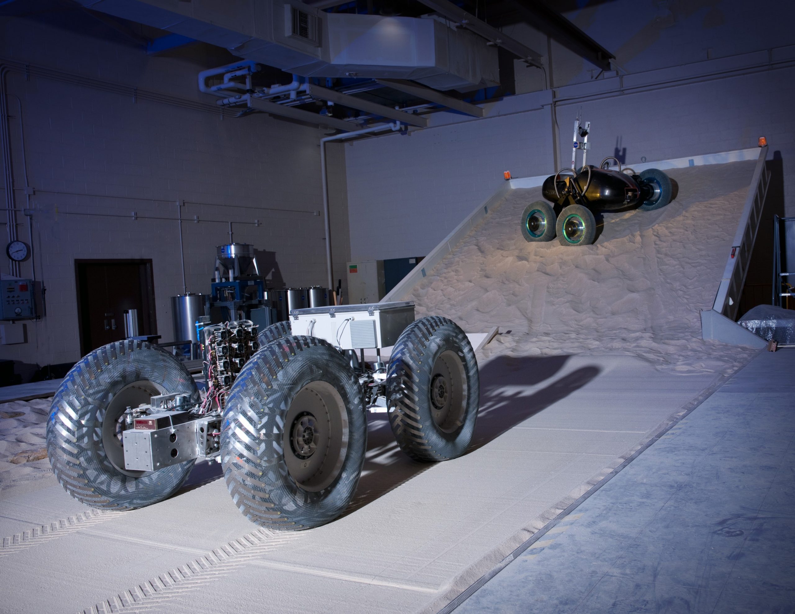
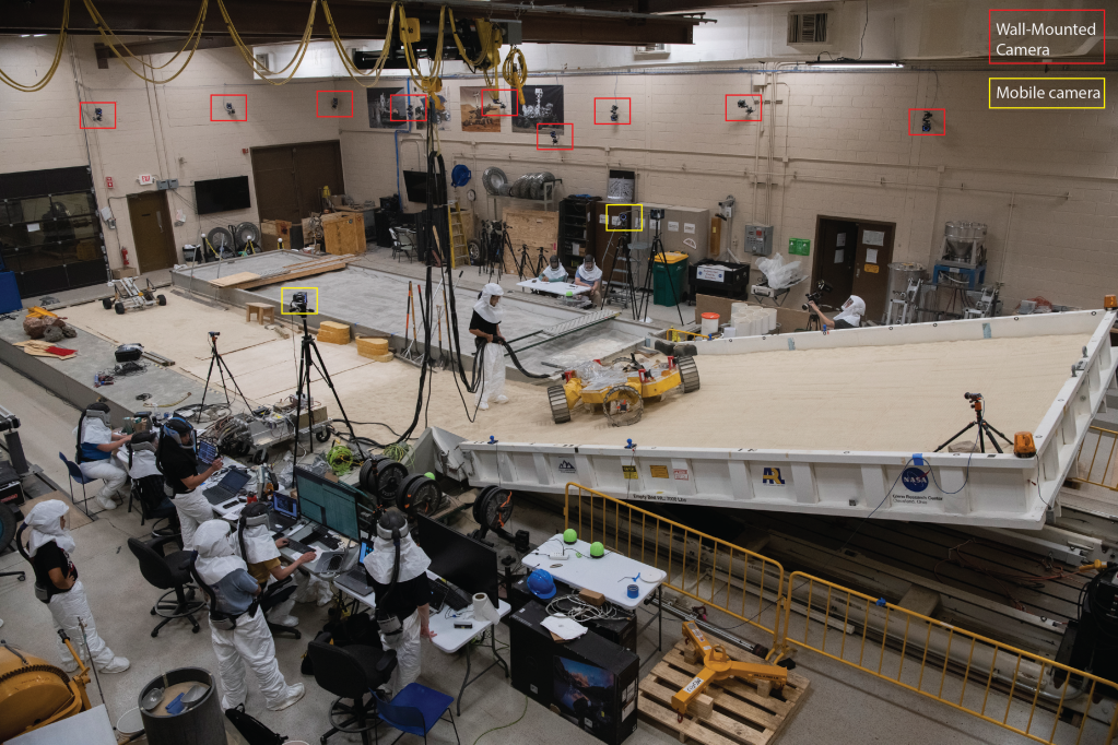
The Simulated Lunar Operations (SLOPE) Laboratory serves to provide controlled test conditions to evaluate the tractive performance of roving vehicles on simulated lunar and Martian terrain. Because the lab is indoors, the facility has stable temperature and humidity levels, which limit variability in soil conditions between tests. Full-scale vehicles or sub-systems and components can be tested here.
The lab consists of three distinct test areas:
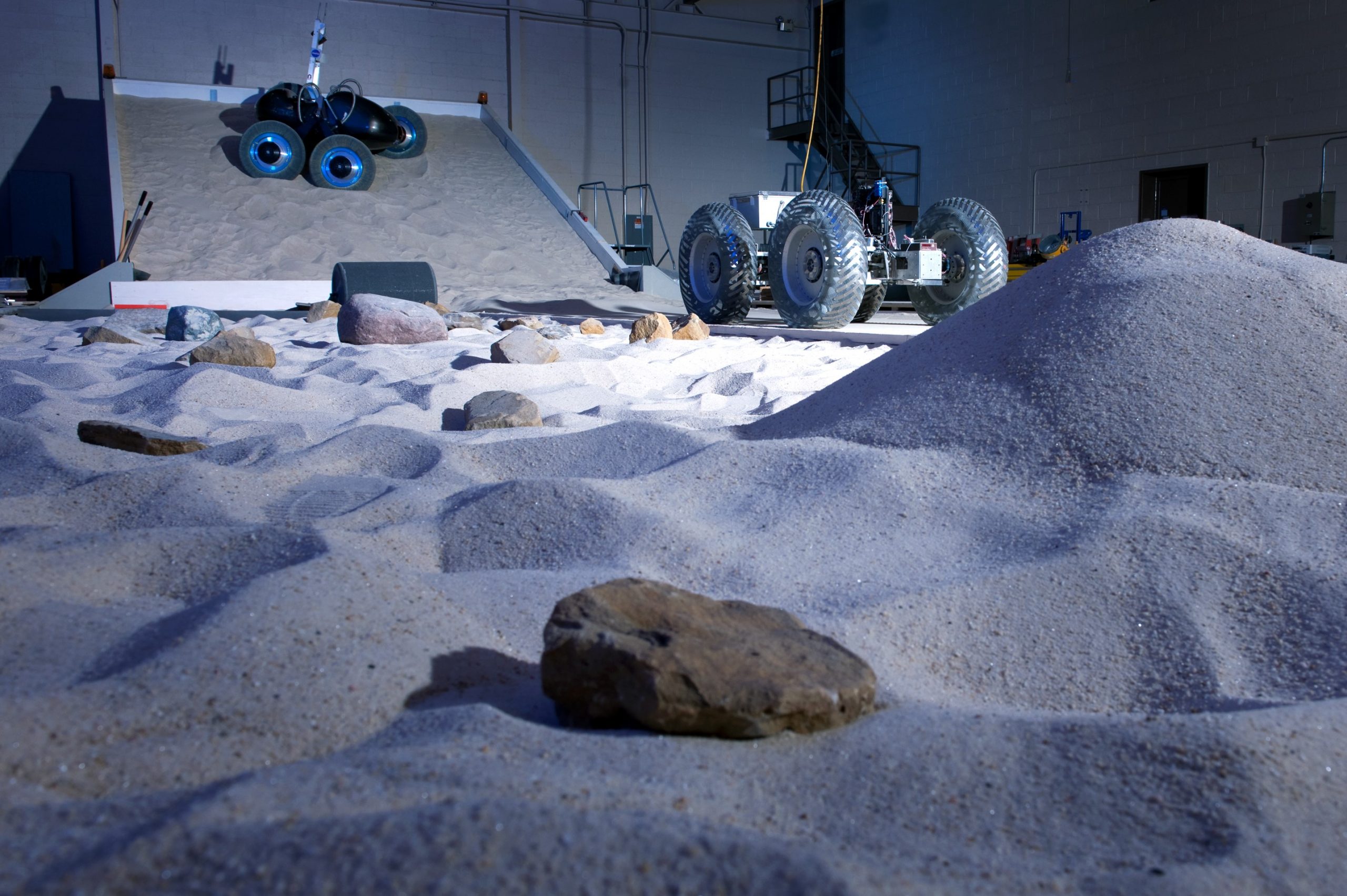
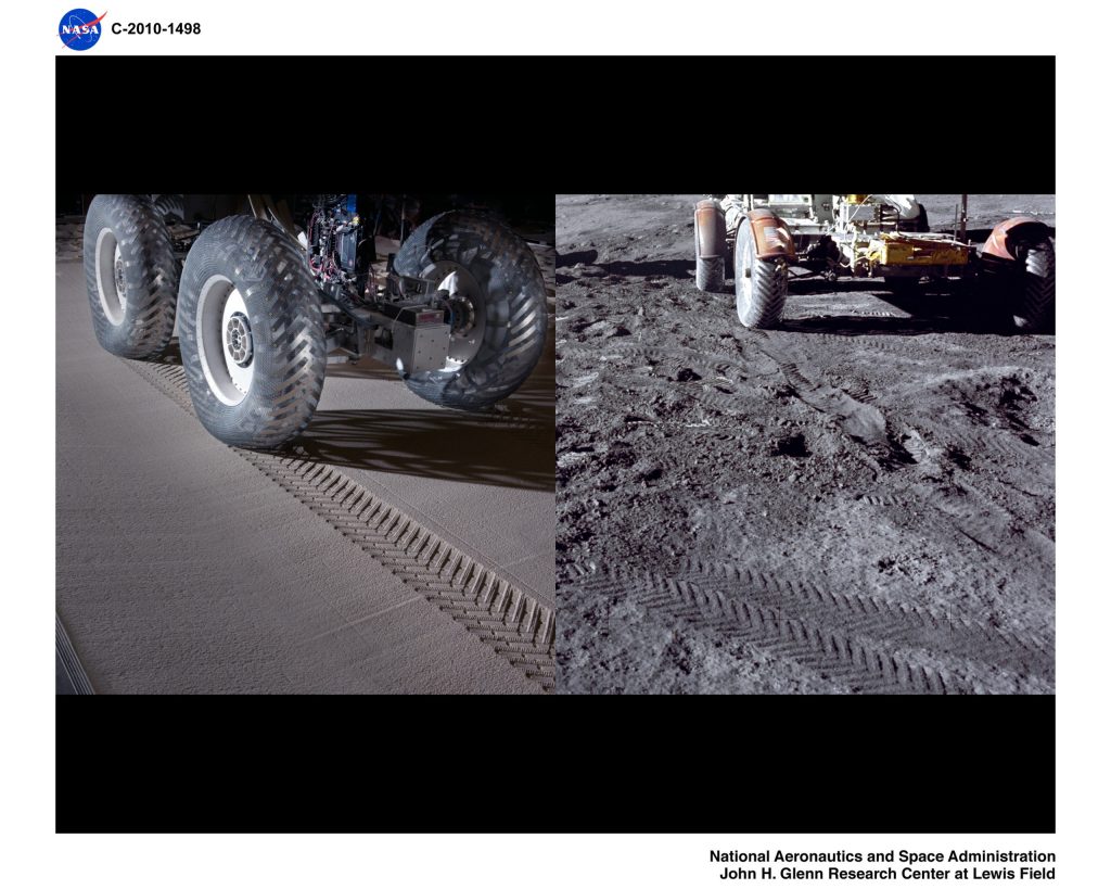
- 12m x 3m x 0.3m soil tank filled with GRC-1 lunar simulant. Here, vehicles can traverse prepared lunar simulant as well as obstacles to assess performance. A drawbar pull rig can be positioned at the end of the test bed, which applies a desired resistive force to the rover via a smart-winch system. The tractive performance of the rover or its mobility components can be assessed as a function of drawbar pull force.
- 6m x 5m x 0.3m adjustable tilting soil tank. Using a hydraulic lift system, the tilt-bed is adjustable up to 45 degrees of inclination for sloped surface operations; however, the maximum angle is typically limited by the angle of repose of the simulants in the bed. Currently the tilt-bed is filled with GRC-1 but can be changed out to the desired granular material.
- 12m x 3m x 0.6m “Sink Tank.”. This soil tank is twice as deep as the others and filled with a high-sinkage material called “Fillite.” Due to its particle shape, this material mimics the wind-blown dune soil on Mars and has extremely low shear strength, which produces a very challenging trafficability case for roving vehicles.
The SLOPE Lab is equipped with 32 infrared OptiTrak motion tracking cameras. 20 are mounted permanently on the walls, and 12 are on tripods, providing a full 360-degree field of view. The test vehicles or subjects can be outfitted with trackers so that the rover position and orientation, with sub millimeter accuracy, can be captured in real time.

The soil tanks in the SLOPE Lab are currently filled with two simulants: GRC-1 lunar simulant and Fillite high-sinkage medium. GRC-1 is a custom poorly graded soil consisting of semi-angular silica particles. It was developed to match the bulk strength properties of the equatorial lunar terrain explored during the Apollo missions, with a focus on targeting the “softer,” more conservative range of properties with respect to vehicle mobility. The soil density can be controlled, providing a range of conditions. Fillite consists of hollow alumino-silicate microspheres and is intended to mimic the wind-blown dune soil found on Mars that has produced entrapped conditions for rovers. Though the material is not a high-fidelity simulant, it has low bearing and shear strength and produces a very challenging case for roving vehicles. The material in the soil tanks can be changed out for alternate simulants upon request.
View a virtual tour of the SLOPE Lab.
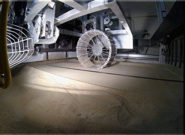
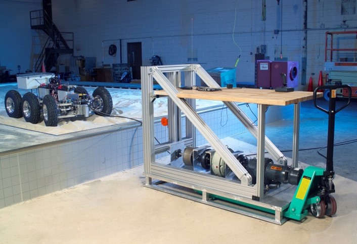
TRaction and Excavation Capabilities (TREC) Rig
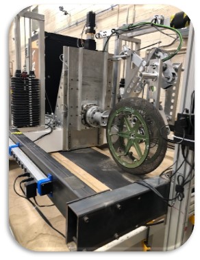
The TRaction and Excavation Capabilities (TREC) Rig is a single-wheel dynamometer used to determine the tractive performance of various wheel and tire designs in simulated lunar and Martian soils. The TREC Rig offers independent motion control of the carriage and the tire such that forced slip conditions ranging from 0 to 90% can be achieved. The vertical tire load is adjustable from approximately 90 N to 900 N, including off-loading capability. The linear speed is also adjustable with a maximum rate of 6 cm/s. Tires up to 95 centimeters in diameter can be tested in the rig’s current configuration.
An in-hub mounted six-axis load cell captures the drive force and the ground force such that a net traction versus slip curve can be generated. Forces up to 900 N and torques up to 230 Nm can be applied and measured at the wheel. In addition, a laser displacement sensor is used to measure and record the tire sinkage with time.
The TREC rig features two available simulants contained in adjacent soil tanks that are 3m x 2m x 0.75m in depth. One tank contains GRC-3, a custom silty-sand lunar soil simulant consisting of semi-angular silica particles and Bonnie silt to provide added strength for In-Situ Resource Utilization considerations such as excavation. It can be prepared to a wide range of densities. The other tank contains a commercial sand identified as #90: a poorly graded silica sand designed to represent the aeolian regions of the Martian terrain.
A semi-automated rake and screed method is used to prepare the simulants to repeatable conditions. Similar to SLOPE, the simulant in the TREC soil tanks can be removed and replaced with alternate granular media upon request.
In addition to single wheel tractive performance, the dynamic and static net traction of a tire or wheel over bedrock can be obtained using the TREC rig.
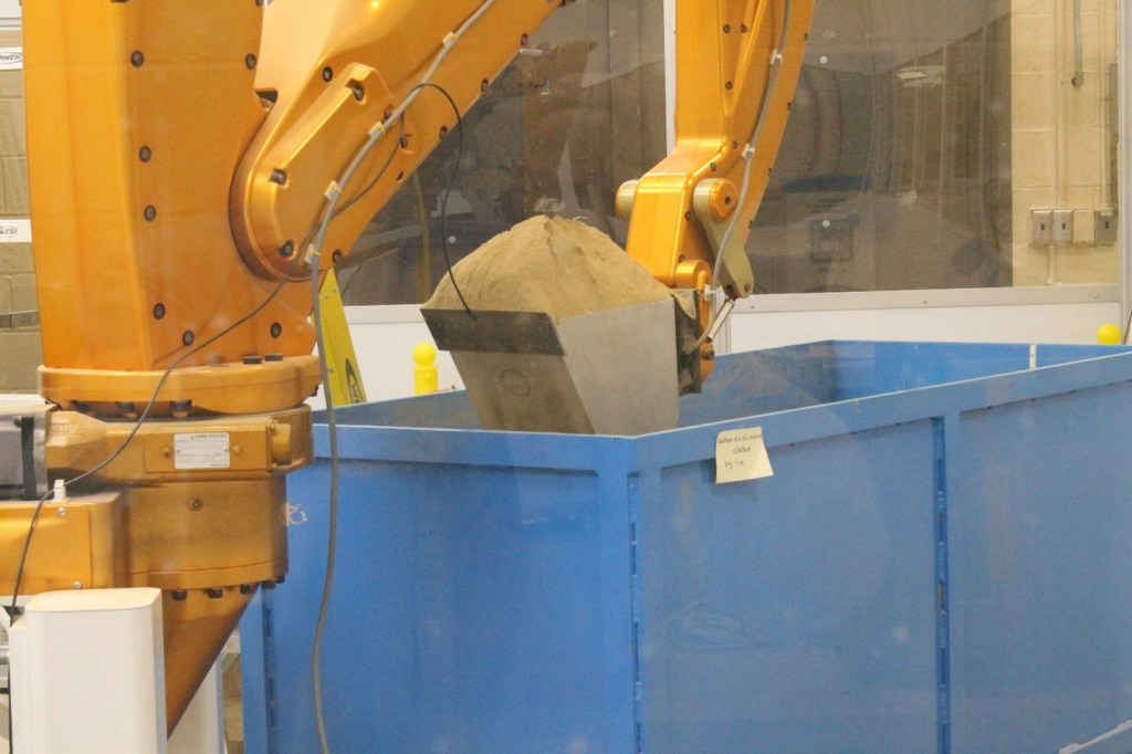
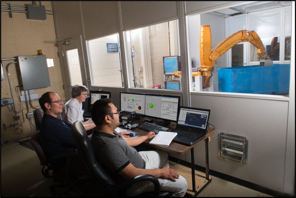
Excavation Lab
This laboratory is used to test and develop excavation tools and techniques for lunar and planetary human and robotic surface operations in granular simulated regolith.
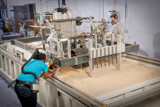
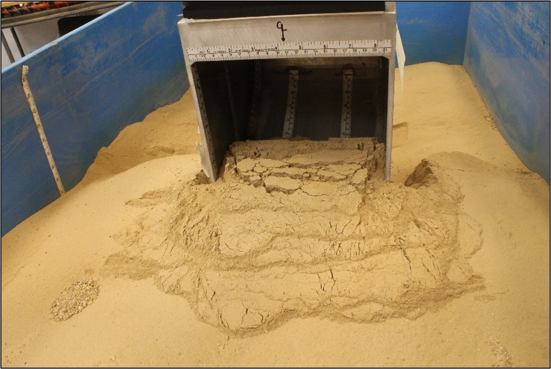
The Advanced Planetary Excavator (APEX), a heavy-duty robotic arm capable of excavating from multiple adjacent soil bins, is used to evaluate excavation tools and forces. The APEX is a four-degree-of-freedom, backhoe-like robotic arm designed to expose only sealed rotary joints to environmental dust. It can rotate 360 degrees around a vertical axis. It has a >2m reach, fine position control, and power and ethernet available to the implement on the end of the arm. Excavation tools can be lowered to desired digging depths and driven at controlled rates on pre-programmed paths while digging forces are measured using a six-axis load cell. The APEX operates by electrical linear actuators.
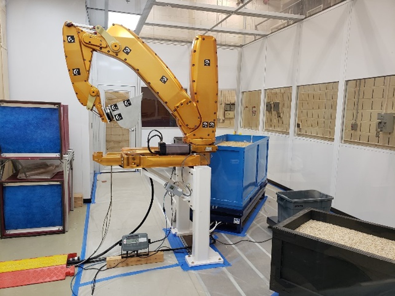
Currently, GRC-3B, a specific silica sand and silt mixture with particle size distribution that is similar to lunar regolith, is used to simulate the geotechnical properties of lunar regolith. Other simulants can be used. A dust enclosure with HEPA filter air exchange surrounds the APEX and soil bins to protect operators from respiratory hazards. The soil bin sits on a shaker table used to compact the simulant.
Test Capabilities
- Test duration: user defined
- Power to experiments: excavation tools can be tethered (wall AC power) or powered from APEX (nominally 300 VDC)
- Data: force, torque, mass of soil dug, depth, velocity, data from tool, power
- Thermal environment of test hardware: lab ambient (air-conditioned)
- Operation: joy-stick control and designed planned trajectories for repeatability
Advanced Planetary Excavator (APEX) Specifications
- APEX can rotate 360 degrees
- 3-meter maximum swing around radius with bucket and load cell
- APEX has electrically powered linear actuators
| Joint | Max Speed | Full Throw |
|---|---|---|
| Shoulder | 4.67 cm/s | 5.42 sec |
| Elbow | 9.37 cm/s | 2.71 sec |
| Wrist | 11.71 cm/s | 1.31 sec |
- Max vertical force = 1165 lbf / 5184 N
- As installed in Excavation Lab:
- Max vertical force controlled to 900 lbf / 4005 N
- Max horizontal force controlled to 400 lbf / 1780 N
- Six-axis load cell:
- Range: 1300 N Fx, Fy and 3900 N Fz; 203 N-m Tx, Ty, Tz
- FS uncertainty: 1.25% Fx, Fy, Tx, Ty; 2.00 % Fz and Tz
- Diameter: 156.5 mm
Other Specifications
- Facility 208 VAC – 3 phase power is converted to 325 VDC, 100 amps to power the actuators
- Pea Gravel bin: 61 cm W x 91 cm L x 51 cm H
- GRC-3B soil bin: 76.2 cm W x 183 cm L x 76 cm H – sits on shaker table
- Dump bin sits on 61 cm x 61 cm platform scale to weigh delivered load
- Shaker table: 81 cm W x 188 cm L x 36 cm H, 22.24 kN Max. load
- Digital power meter is used with 50-amp shunt to measure DC power to APEX
- Platform scale:
- 61 x 61 cm
- Range = 2224 N x 0.22 N
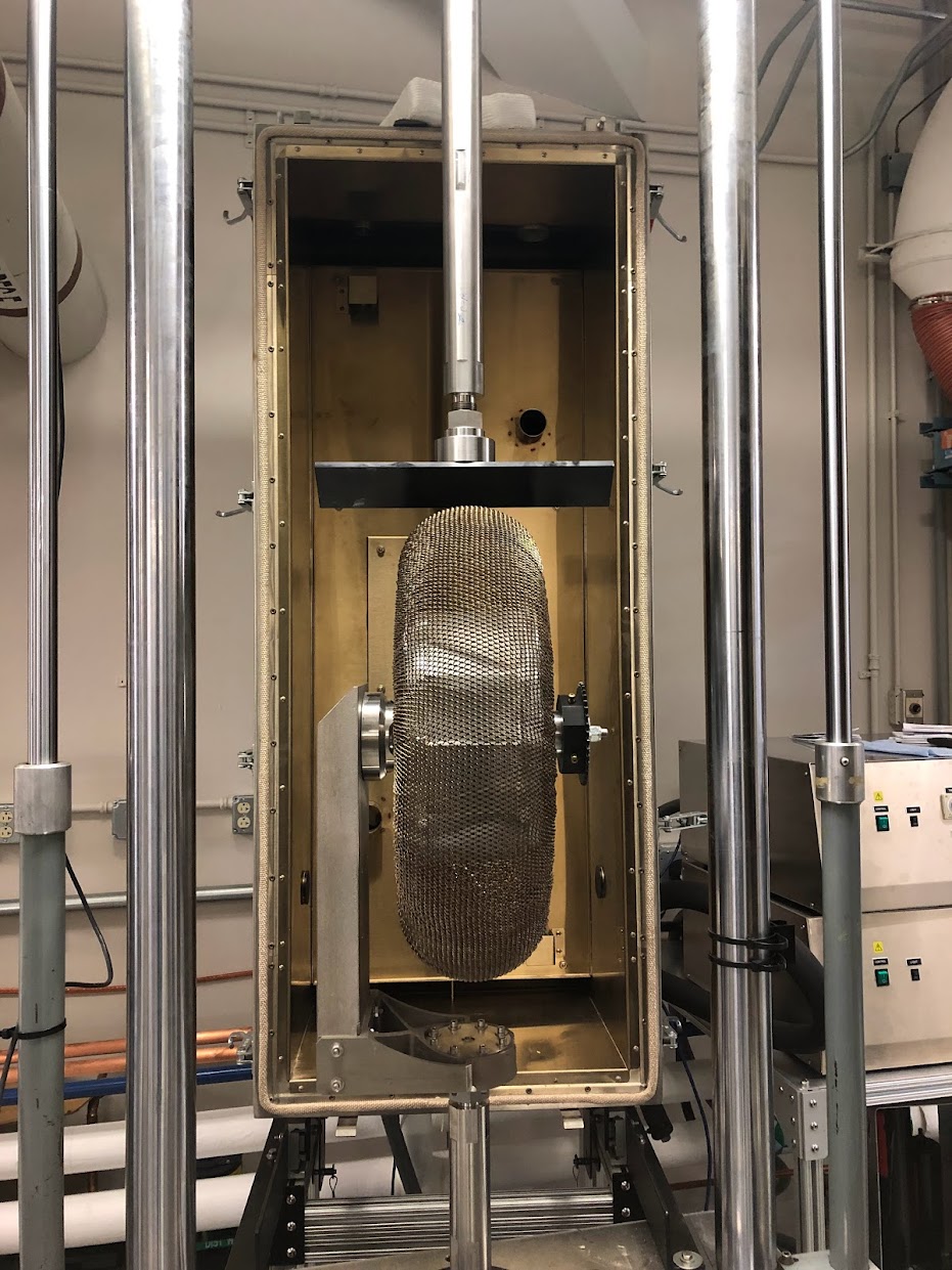
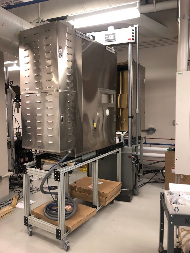
Extreme Cyclic Environmental Load (XCEL) Test Rig
The Extreme Cyclic Environmental Load (XCEL) Test Rig is a hydraulic load frame coupled with an environmental chamber sized to enclose a full-scale wheel or tire. This test rig is used for cyclic radial compression tests at temperatures ranging from 133K (lowest tested to date) to 370K. Liquid nitrogen or liquid carbon dioxide can be used to cool the chamber to the desired temperature. The nominal inner dimensions of the environmental chamber are 139 cm tall x 101 cm deep x 50 cm wide. The maximum tire size is dependent on the hardware and fixture needs, as well as stroke length. The nominal cyclic rate is 1 Hz.
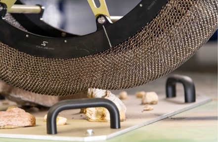
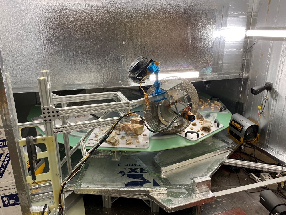
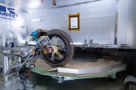
Extreme Terrain Endurance Rig (XTERra)
The Extreme Terrain Endurance Rig (XTERra) is a new single-wheel life test rig used to evaluate the durability of new wheels and tires at planetary temperatures over representative terrain elements. The XTERra carousel and tire are independently driven to create a forced slip condition ranging from 0 to 100%. The maximum linear speed is on the order of 100 cm/s depending on the desired tire load. The chamber can be heated up to 60°C. It can also be cooled, though the coldest achievable temperature is currently unknown. Tires up to 95 centimeters in diameter can be tested in XTERra.
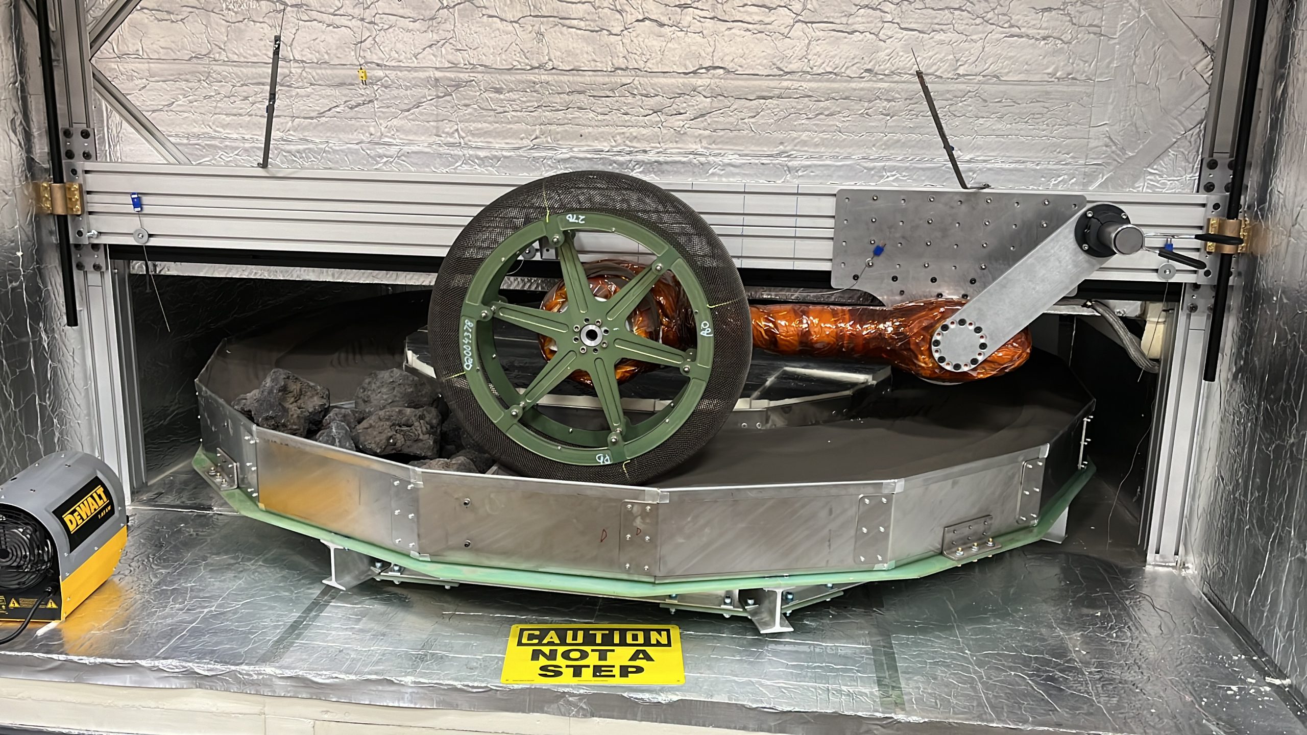
During a life test, a six-axis load cell records loads and torques directly at the tire. Vertical motion of the tire can be recorded via an inclinometer on the mounting arm. Several thermocouples are mounted throughout the chamber to obtain temperature readings. Cameras are also mounted in front and to the side of the tire. The vertical force can be set up to 1,000 N (up to 2,500 N peak instantaneous) and a maximum continuous torque of 300 Nm (up to 500 Nm instantaneous) can be applied to the tire.
The terrain can be customized to include different types of regolith or rocks.
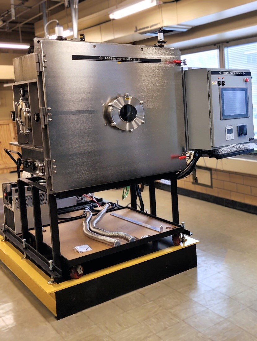
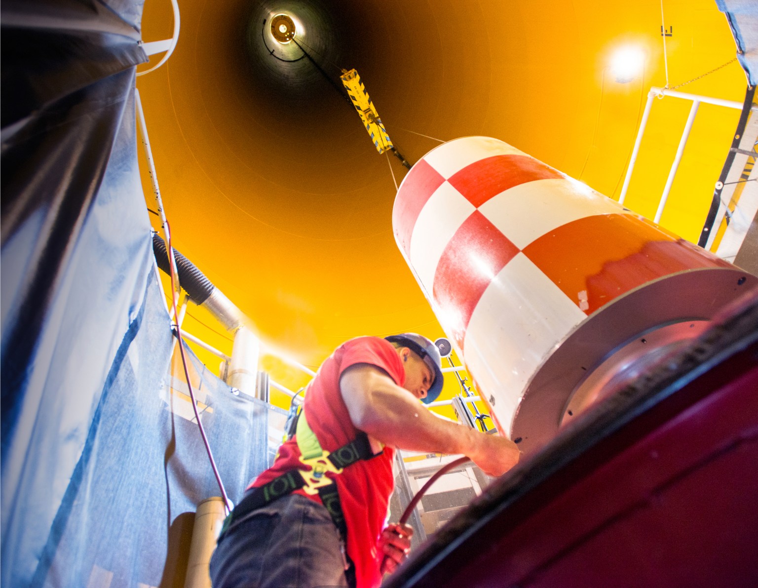
The Vacuum Operations in Dust Environment (VOiD) Chamber
The test rig provides capability to study sub-meter cubed experiments in simulated extraterrestrial environments. Designed to operate under thermal and vacuum control with regolith simulant in the chamber, the chamber serves to promote the Technology Readiness Level (TRL) of payloads past component-level testing.
Technical Capabilities
A thermal shroud inside the chamber is cooled with LN2 dewars and heated with internal heaters. A series of filters and a throttle valve allow safe pump down with simulant in the chamber.
| Name | Value | Unit |
|---|---|---|
| Internal Working Dimensions | 35 W X 35 D X 32.5 H (89 X 89 X 82.5) | in (cm) |
| Working Temperature | -180 to +150 (-290 to +300) | °C (°F) |
| Vacuum Level | 10-6 | Torr |
The test rig includes four mounting points on the ceiling for instrumentation, each with a 50-pound load capacity.
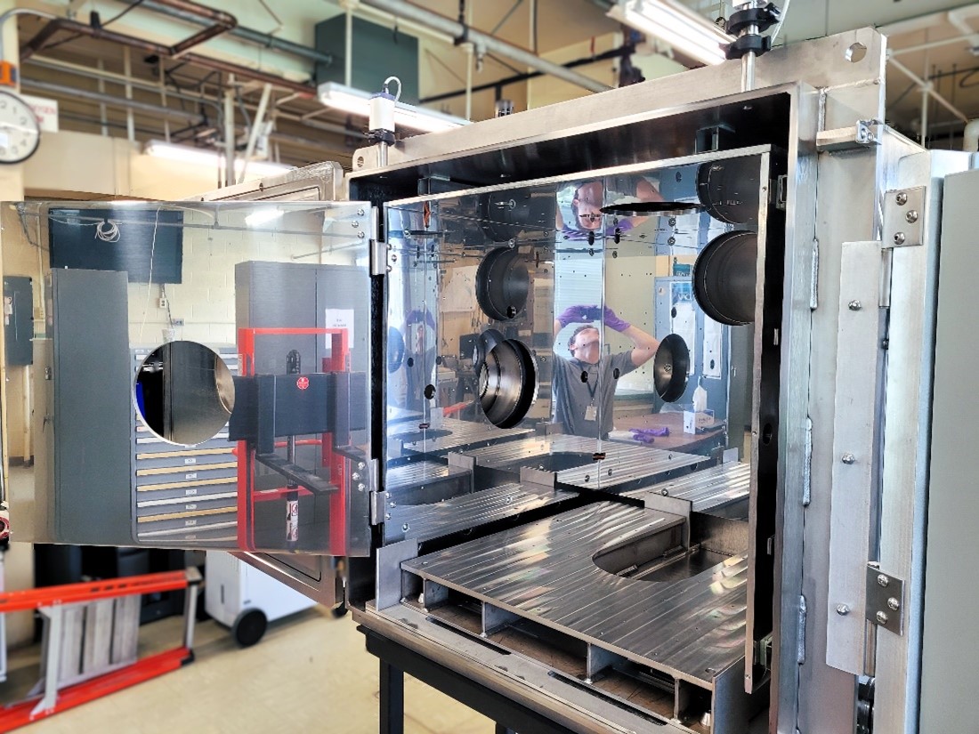
The table below outlines several auxiliary ports for use by the customer for thermocouple, power, and data feedthrough. All of the auxiliary ports are KF / QF or LF type flanges, which allows for faster and cheaper instrument installation. The DN-250 ports and two of the DN-40 ports are line-of-sight to the center of the chamber.
| Size | Type | Quantity |
|---|---|---|
| DN-40 | KF / QF | 14 |
| DN-63 | LF | 2 |
| DN-250 | LF | 5 |
Contact
Engine Research Building (ERB)
Facility Manager: Gwynn Severt
216-433-8310
Gwynn.A.Severt@nasa.gov
Test Facility Management Branch
Acting Chief: Taylor Varouh
216-433-6347
Taylor.Varouh@nasa.gov
Using Our Facilities
NASA’s Glenn Research Center in Cleveland provides ground test facilities to industry, government, and academia. If you are considering testing in one of our facilities or would like further information about a specific facility or capability, please let us know.
Gallery


/Hubble%20Space%20Telescope%20(A).png)