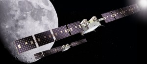


![Request for Information – Potential [Placeholder for Prize]](https://assets.science.nasa.gov/dynamicimage/assets/science/missions/a-step/FFR_Earth_Background_20251120%20.png?w=1024)


Armstrong innovators design and integrate data acquisition systems for research, support, and one- of-a-kind platforms. In many cases, these systems leverage commercial off-the-shelf parts to keep costs low and facilitate integration with legacy systems. At the same time, these cutting-edge data systems are finding innovative ways not only to collect data efficiently but also to flexibly configure collection parameters.
Wireless Flight Sensor System
Researchers at Armstrong are developing a system that eases integration of wireless sensors into existing aircraft avionics. Currently, adding wireless sensors to avionics systems is time consuming and expensive due to integration requirements. This innovation streamlines that process, eliminating the need to overhaul preexisting avionics systems to integrate new sensors. Key to the innovation is a software-defined radio device that implements into software the capabilities of individual wireless protocols and systems. If applied throughout the aviation industry, this approach would enable a clear transition path from experimental use of wireless sensors to practical implementation.
Work to Date
Benefitting from NASA’s Center Innovation Fund, researchers purchased software-defined radio devices and created a preliminary architecture. The team demonstrated in the laboratory the ability for dissimilar wireless devices to communicate without any hardware modifications. The group also worked with two small businesses to test the unique wireless technology on Armstrong aircraft. A resulting analysis recommends its adoption in wireless avionics.
Looking ahead: Next steps are to continue to test the technology in aircraft.
Benefits
- Saves time: Streamlines testing and implementation of wireless technology
- Adds capabilities: Allows new mechanisms and devices to be added to aircraft
- Reduces costs: Simplifies the process of integrating wireless sensors
Applications
- Avionics
- Instrumentation systems
- System health monitoring
PI: Matthew Waldersen | 661-276-5708 | Matthew.Waldersen@nasa.gov
Wireless Miniature Biosensor
This research effort produced a wireless miniature biosensor for real-time in-flight physiological monitoring of the aircrew in high-performance aircraft. The size of a postage stamp, this battery-free sensor measures oxygen saturation, heart rate, heart rate variability, and body temperature. The device was designed specifically to monitor a pilot’s brain oxygen saturation during high-g flight maneuvers. Current oxygenation measurement devices are large and bulky, thus not suitable for use on pilots in high-g conditions. Though designed for pilots, this biosensor offers uses for astronauts, athletes, military personnel, and patients in acute trauma situations.
Work to Date
The sensor technology is functional. Remote sensing and reflective capabilities increased its ease of use and variety of potential applications.
Looking Ahead
The biosensor’s light weight and small size enable the possibility of developing similar sensors to measure additional parameters. For example, cuffless blood pressure monitoring would be useful in high-performance aviation and numerous other situations.
Partners
Wearifi, Inc., and Northwestern University Center for Bio-Integrated Electronics
Benefits
- Powerful: Enables real-time physiological monitoring
- Compact: Features a small and lightweight form factor ideal for use in high-g conditions
Applications
- Aviation
- Spaceflight
- Athletics
- Acute care medicine
- Trauma care
PI: Dwight Peake | 661-276-3217 | Dwight.Peake-1@nasa.gov
Real-Time Parameter Identification
Armstrong researchers have implemented a technique for real-time, control room–based estimation of the aerodynamic parameters that describe an aircraft’s stability and control characteristics. Oftentimes, aerodynamic modeling is performed on recorded data after test flights and then used in simulations. The drawback with this approach is that, if the collected data are not complete or of high quality, additional and costly flight tests must be scheduled.
In this innovative approach, Armstrong’s real-time parameter estimation automates the process and runs during flight, enabling researchers in the control room to evaluate and adjust flight maneuvers to ensure data quality. The technology increases the efficiency and productivity of flight tests, as researchers can determine during the tests if they have collected the data needed for specific modeling simulations.
Work to Date
The system successfully evaluated data from the Gulfstream III aircraft as part of the Adaptive Compliant Trailing Edge (ACTE) project and is currently being used in Armstrong control rooms to evaluate data collected during test flights and in-flight maneuvers. Researchers have continued to improve the system display and refine the way that results are presented.
Looking Ahead
A capability to compare the estimated parameters to preflight predicted values is being added, which will make it possible to evaluate the aerodynamic effects of aircraft modifications. The system is expected to become part of Armstrong’s control room toolset for use with upcoming X-planes and other projects. Accordingly, researchers are working to implement an updated version of the code for the X-57 Maxwell all-electric aircraft.
Benefits
- Automates data collection: Estimates in real time the parameters for aircraft stability and control
- Improves data quality: Enables adjustments during flight tests to ensure correct data acquisition
- Saves time and resources: Decreases the duration and number of flight tests
Applications
- Aerodynamic modeling
PI: Mark Smith | 661-276-3177 | Mark.S.Smith@nasa.gov
Mechanoluminescent Materials
Aerospace structures are composed of fiber-reinforced polymer composites that are susceptible to interior delamination during high-frequency vibrations. Armstrong and university researchers are collaborating to design and test a mechanoluminescent optoelectronic (MLO) material that can autonomously detect internal delamination. Composed of a conductive polymer with a photoactive layer and an elastomer embedded with crystals, the material converts mechanical energy into light energy to provide information about the structure and its properties. These flexible, self-powered multi-functional MLO materials could be a lightweight, sensitive solution for warning when a wing or other aerostructure is enduring excessive strain or is at risk of catastrophic failure.
Work to Date
Researchers conducted vibration tests on an MLO-equipped cantilevered wing in the Flight Loads Lab at Armstrong in summer 2019. Measurements were compared to those from conventional strain gauges and accelerometers.
Looking Ahead
The team will use lessons learned during vibration tests to improve sensor manufacturing techniques to increase robustness and operability. Next steps are to develop consistent fabrication techniques to meet quality control standards and calibration techniques to capture sensor behavior for comparison. The team will repeat ground testing on an aerospace test article to verify sensor improvements and further characterize the technology’s potential for use in structural health monitoring.
Partners
University of New Mexico, New Mexico Institute of Mining and Technology, and New Mexico State University
Benefits
- Safety enhancing: Detects internal delamination of aerospace composite materials
- Self-powering: Generates power from mechanical vibrations
Applications
- Structural health monitoring
- Power generation
PI: Alexander Chin | 661-276-2681 | Alexander.W.Chin@nasa.gov
ARMD Flight Data Portal
Armstrong is taking the lead on a NASA-wide effort in the Aeronautics Research Mission Directorate (ARMD) that will enhance flight research and test capabilities by improving the management of test data. The ARMD Flight Data Portal (AFDP) will replace the legacy Flight Data Access/Archival System (FDAS), in place since 1980. An effective resource for its time, FDAS archives flight data but offers no corresponding analysis or related information. The new data portal will archive all test flight data for the four NASA centers involved in flight testing along with contextual information needed to understand and analyze the data. Such information includes mission overviews, flight profiles, daily summaries, mission debriefs, and more. A robust search mechanism and intuitive graphical user interface (GUI) will further make the AFDP a meaningful flight test resource. Online and accessible to all with NASA credentials, the AFDP will increase collaboration across NASA centers.
Work to Date
Work began in 2016 and is proceeding in three phases. Phase 1 involves the upfront work to build the portal, and Armstrong is leading this effort. The team is focusing on the X-57 Maxwell airplane as a test case, including all flight data and contextual information to ensure the portal operates as intended.
Looking Ahead
Future phases will intended to include various flight test projects from NASA’s other three ARMD Centers— Ames, Glenn, and Langley Research Centers.
Benefits
- Enhances research capabilities: Enables rapid location of test flight, simulation, and loads test data along with corresponding contextual information
- Increases collaboration: Accessible to all NASA personnel via online system
- Is easy to use: Features a user-friendly GUI and search mechanism
PI: David Tow | 661-276-3552 | David.Tow-1@nasa.gov
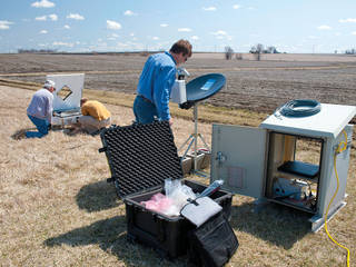
Atmospheric Science Team
For the atmospheric science team at Armstrong, every day is different as they work to support the center’s many research projects. The team’s capabilities and activities are as broad and as varied as the efforts they support and the types of data they provide to science, aeronautics, and other missions.
In addition to weather forecasts—needed for flight safety and mission planning—the team provides post-flight information that is critical for engineering analysis, such as atmospheric references for air data calibrations and airspeed data for determining errors in aircraft measurements.
The team uses its wide knowledge base and state-of-the-art technology to support a variety of efforts, each with its own unique requirements. For example, some research projects need to know wind conditions every 5 minutes, whereas others need wind measured just once an hour. The team is also responsible for helping determine if conditions are appropriate for testing, and the requirements range the spectrum. To continue with the wind example, some projects cannot operate with wind speeds over 5 knots, others can operate in winds up to 30 knots, and for some, wind speeds do not matter at all.
The team leverages numerous cutting-edge tools to achieve useful results for the widely varying projects:
- Surface measurement systems determine temperature, pressure, humidity, wind speed and direction, solar radiation, precipitation, air quality, and more.
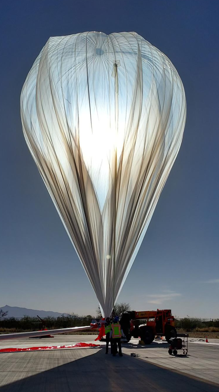
- Balloon systems measure temperature, humidity, and pressure while using GPS to determine wind speed and direction. Armstrong has three balloon systems, and the team can send them as high as 130,000 feet to collect samples at multi- second intervals, depending on project requirements.
- Sodar anemometers use sound to measure wind speed and direction at various altitudes. The team uses its 2,000- and 4,000-hertz systems to leverage data on atmospheric turbulence and the scattering of sound waves for needed measurements.
Other key tools include lidar and radar systems for various wind measurements, towers for heat stress measurements, and tethersondes for obtaining atmospheric boundary layer measurements. Here are just a few examples of how Armstrong’s atmospheric science team has supported NASA research.
Acoustic Research Measurement (ARM) Flights
The ARM project tested technologies to pinpoint airframe noise sources during landings. To enable the analysis, the team monitored atmospheric conditions while a Gulfstream-III aircraft flew 700 feet above a microphone array in a lakebed. Tools included a weather tower on the lakebed and a tethersonde unit to measure temperature, pressure, relative humidity, and wind speed and direction at 1-second intervals.
Low-Boom Flight Demonstration (LBFD)
One of the goals of the LBFD mission is to gather data on human responses to sonic booms. For the Quiet Supersonic Flights 2018 (QSF18) research, the team launched balloons that collected atmospheric data, enabling pilots to place sonic booms in specific locations.
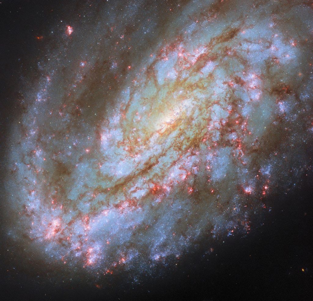
Stratospheric Observatory for Infrared Astronomy (SOFIA)
In addition to weather forecasts, the team provides water vapor loading information to the SOFIA crew. This information enables the crew to understand the amount of water vapor in the upper atmosphere, aiding telescope views. The team also provides real- time satellite and other data, enabling the crew to compare this data with that of their instruments and monitors.
PI: Edward Teets | 661-276-2924 | Edward.H.Teets@nasa.gov
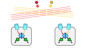
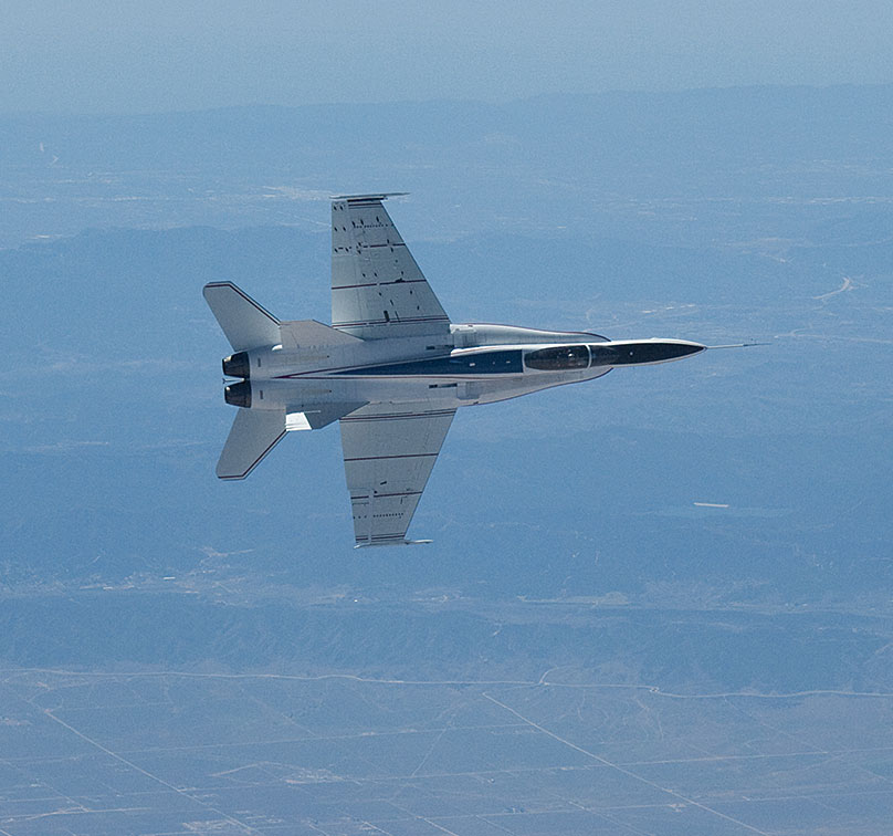
Visual Radar
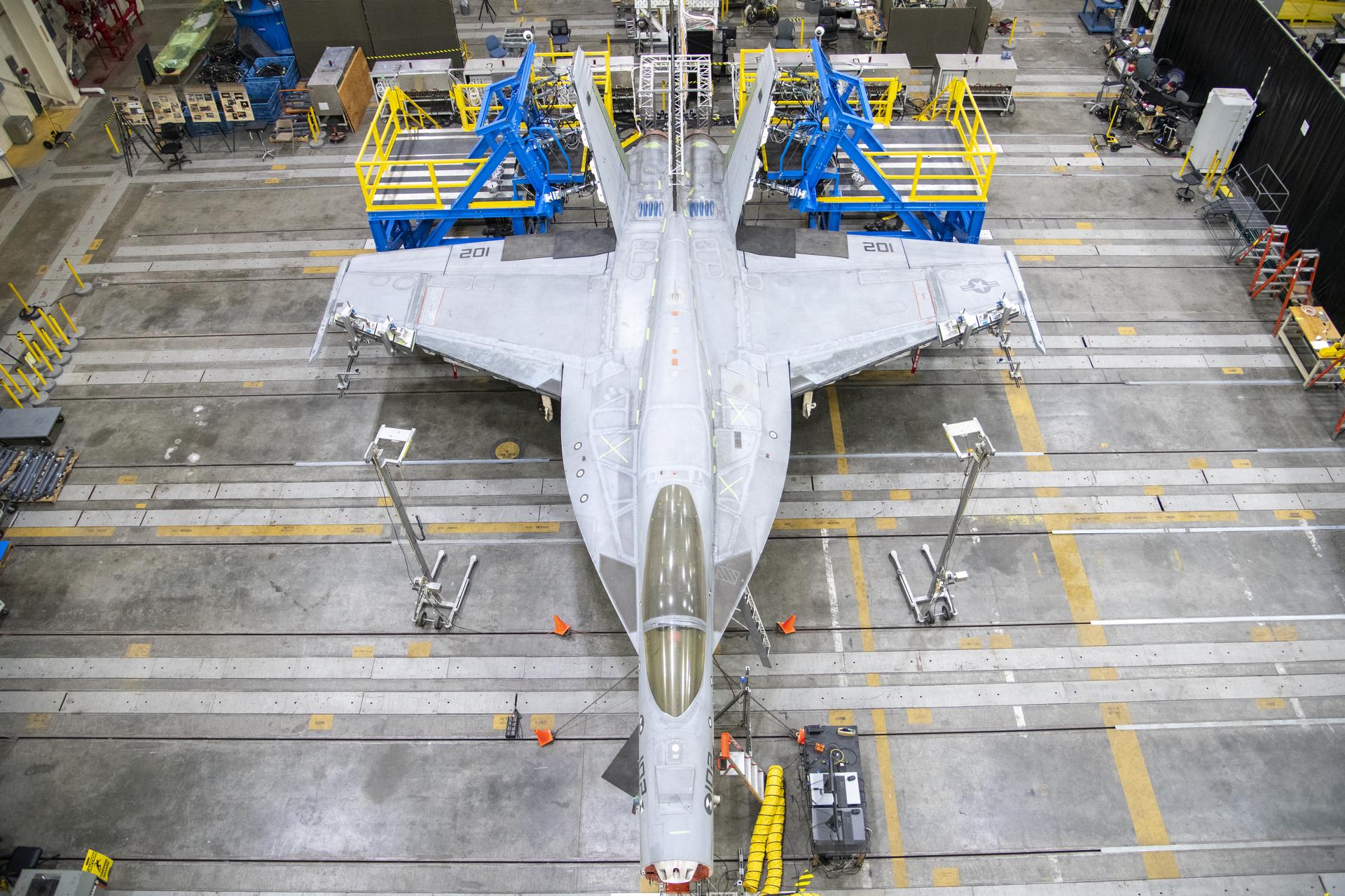
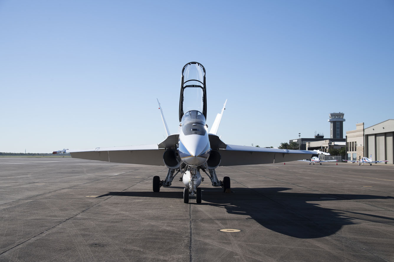
Researchers at Armstrong and NASA’s Jet Propulsion Laboratory (JPL) are collaborating to validate and test a stereo vision technology for terrain-relative navigation. Stereo vision utilizes two cameras with the same field of view to generate ranging data from a binocular image using the known distance between the cameras. JPL researchers developed the technology for robust, vision-based, terrain-relative navigation based on two non-static cameras. Armstrong researchers are integrating and flight testing the new technology on an F-18 aircraft. The innovation could lead to advances in aircraft sensor systems.
Work to Date
With funding from NASA’s Center Innovation Fund, Armstrong and JPL researchers collaborated to develop flight hardware to validate the technology. The Armstrong team integrated the cameras into two instrumentation pods that will be fitted onto the wing tips of an F-18 aircraft. To save resources, researchers used existing aircraft and instrumentation pod wiring. Significant accomplishments include:
- Retrofitted Navy instrumentation pods with camera systems
- Completed environmental testing
- Finalized flight planning
- Completed integration design
Looking Ahead
Following integration and flight testing, the system will be used by NASA’s Resilient Autonomy project for unmanned aircraft research.
Partner
NASA’s Jet Propulsion Laboratory
Benefits
- Innovative: Demonstrates the ability to use cameras as visual sensors
- Advanced: Enables a new type of 3D mapping for the unmanned aircraft world
- Rugged: Useful for detecting hazards in flight environments
Applications
- Autonomous flight techniques
- Automatic collision avoidance technologies
- 3D modeling of terrain and structures
- Passive object detection
PI: Matthew Versteeg | 661-276-3902 | Matthew.L.Versteeg@nasa.gov
Ethernet via Telemetry
This research effort is focused on developing a network-based telemetry system that transmits data between ground stations and research aircraft using less bandwidth than traditional telemetry methods. The Ethernet via Telemetry (EVTM) system is an improvement over static, one-way pulse code modulation–based systems that crowded the frequency spectrum as research projects became more complex and involved larger amounts of data. The new system can move data at 40 megabits per second (Mbps), 10 times faster than current systems Armstrong researchers are using. EVTM establishes a dynamic link between ground stations and research aircraft, enabling users to specify data rates and reallocate resources to free up space for other applications.
Work to Date
In 2017, EVTM was utilized in a flight-testing environment when Armstrong hosted a captive carry test by Generation Orbit. The launch services company needed a telemetry system that easily integrated with its embedded data system. EVTM was utilized along with custom Python® software to integrate Generation Orbit’s parameters into the programming language displays.
In 2018, further work was done to better utilize EVTM in a method to allow dynamic subscription to instrumentation data. Using standard network technologies allows tools to change the telemetry stream dynamically. With funds from NASA’s Center Innovation Fund, researchers developed a ground-based system to prove this concept.
Looking Ahead
The team is investigating how to use EVTM to advance flight test data acquisition capabilities.
Benefits
- Versatile: Features direct Ethernet network compatibility and provides bidirectional communication
- Efficient: Allows for real-time ground-based experiment control while using less bandwidth
- Reconfigurable: Allows the downlink data architecture to be configured as needed
- Convenient: Allows frequency spectrum reallocation
Applications
- Commercial, military, and general aviation aircraft
PI: Otto Schnarr | 661-276-5114 | Otto.C.Schnarr@nasa.gov
Python is a registered trademark of the Python Software Foundation.
Advanced Propulsion Instrumentation
Armstrong researchers are working to identify, develop, and test new instrumentation components and systems that can effectively evaluate next-generation integrated propulsion systems. A wide variety of legacy instrumentation exists to effectively characterize and provide flow measurements and visualization on and off surfaces around an aircraft propulsion system. However, as novel propulsion systems and configurations evolve, new instrumentation will be needed to evaluate them. Future technologies will be looking to exploit the unique complexities of advanced propulsion system configurations to increase efficiency, and the challenge is to develop appropriate flight test instrumentation tools and methods.
Work to Date
Capabilities currently in development include:
- Low-profile conformal pressure sensors
- Low-profile conformal shock and transition detection sensors
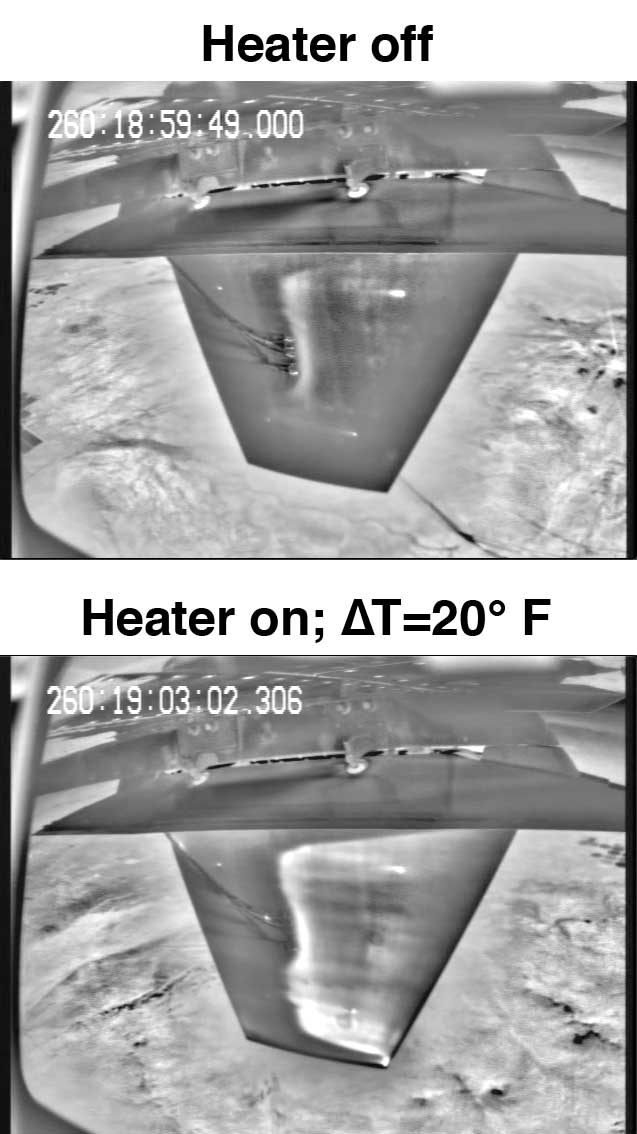
- Carbon-based heating layer for laminar/turbulent flow visualizations
- Pressure-sensitive paint for in-flight use
- Wireless sensor and instrumentation sensor technologies
Looking Ahead
Armstrong researchers have identified several tools and methods for further research and development:
- Improved off-surface flow measurements and visualization (e.g., particle image velocimetry)
- Improved flight-capable pressure sensors
- Less intrusive sensors and visualization techniques
- Improved engine modeling for flight tests
Benefits
- Enabling: Supports NASA’s efforts to facilitate development of future propulsion systems
- Informing: Aids in determining how to apply resources for next-generation technologies
PI: Stephen Cumming | 661-276-3732 | Stephen.B.Cumming@nasa.gov
Flying Observatory
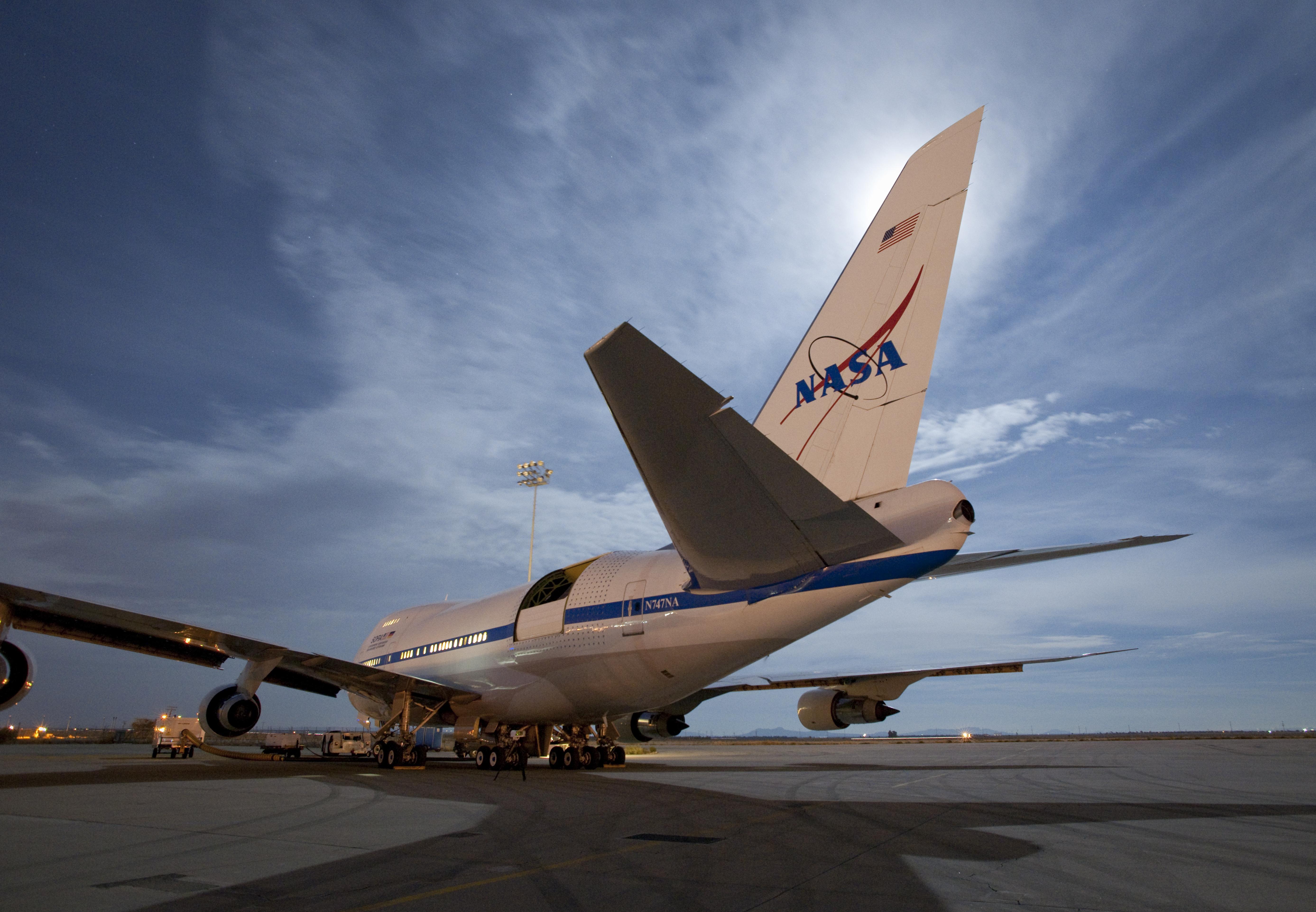
The Stratospheric Observatory for Infrared Astronomy (SOFIA) is a Boeing 747SP jetliner modified to carry a 106-inch diameter reflecting telescope. It is a joint project of NASA and the German Aerospace Center, DLR.
Flying in the stratosphere at 38,000 to 45,000 feet puts SOFIA above 99 percent of Earth’s infrared-blocking atmosphere, allowing researchers to study the solar system and beyond in ways that are not possible with ground-based telescopes. During hours-long flights, SOFIA’s telescope instruments—cameras, spectrometers, and polarimeters—operate in the near-, mid-, and far-infrared wavelengths to study various phenomena and gather data.
Armstrong operates and maintains the aircraft. Unlike space-based telescopes, SOFIA lands after each flight, so its instruments can be exchanged, serviced, and/or upgraded to leverage new technologies, retaining state-of-the-art capabilities. As a working observatory with a vigorous outreach program, SOFIA is a place for scientific exploration.
PI: Michael Toberman | 661-276-2711 | Michael.D.Toberman@nasa.gov
Portable Data Acquisition System
Armstrong researchers have developed a Portable Data Acquisition System (PDAT) that can be easily transported to and set up at remote locations to display and archive data in real time. The PDAT was developed to collect data from strain gauges and fiber optic sensors installed on a revolutionary wing flap while it was being constructed by NASA partner FlexSys Inc. in Ann Arbor, Michigan, as part of the Adaptive Compliant Trailing Edge (ACTE) project. The PDAT enabled the Armstrong team to monitor and analyze data during the construction process and provide vital feedback to designers on site at FlexSys instead of having to wait until construction was completed and shipped to Armstrong’s facility.
Work to Date
This unique and flexible system has 64 channels for analog data, 32 channels for thermocouples, and 6,000 parameters of fiber optic data. It is currently configured to gather strain gauge and thermocouple inputs, but a variety of other hardware can be installed, including cards for pressure transducers, voltages, currents, motion packs, accelerometers, MIL-STD-1553 and ARINC 429 aircraft data buses, and Ethernet packets.
Looking Ahead
The PDAT has been an integral part of the ACTE project and is versatile enough to become a successful component of many current and future Armstrong projects.
Benefits
- Convenient: This innovation enables real-time analysis of data collected at remote locations.
- Portable: The hardware is easily removable, attaches to a single heat-sink pallet, and fits into a single small case for quick transport. It can be used in a variety of locations, including laboratory, hangar, and flight line.
- Flexible: The technology can be quickly reprogrammed to support various tests, and it can display and archive data from virtual streams.
Applications
- Aircraft engines, commercial rail, and trucks
- Military land transport vehicles
PI: Shedrick Bessent | 661-276-3663 | Shedrick.B.Bessent@nasa.gov
Networked Instrumentation
Armstrong researchers have developed a networked instrumentation system that connects modern experimental payloads to existing analog and digital communications infrastructures. In airborne applications, this system enables a cost-effective, long-range, line-of-sight network link over the S and L frequency bands that support data rates up to 10 megabits per second (Mbps) and a practically unlimited number of independent data streams. The resulting real-time payload link allows researchers to make in-flight adjustments to experimental parameters, increasing overall data quality and eliminating the need to repeat flights.
Work to Date
The team has developed and flight-tested the 10 Mbps bidirectional aircraft-to-ground line-of-sight network. A follow-on project—Space-Based Range Demonstration and Certification (SBRDC) Flight Demonstration #2—involved integration of this system with a phased-array antenna and controller to provide a 10-Mbps over-the-horizon network downlink. This prototype system was further refined into a more operational system that provided the Airborne Research Test System (ARTS) aboard the Full-Scale Advanced Systems Testbed (FAST) access to thousands of parameters from the heavily instrumented aircraft. Engineers were able to view ARTS network data output in the control room, without replacing any aircraft instrumentation or ground equipment.
Looking Ahead
Work has begun to design a new system that incorporates state-of-the-art transceiver technology. The new system is expected to significantly increase throughput up to 40 Mbps.
Benefits
- Flexible: Expands the utility of existing airborne platforms with legacy communications systems by supporting state-of-the-art payloads that leverage current network technology
- Economical: Achieves a bidirectional line-of-sight network without the need to replace existing communications infrastructure
- Flight efficient: Reduces the need for repeat flights by offering real-time control of experimental parameters
Applications
- Hypersonic vehicle research and design
PI: Otto Schnarr | 661-276-5114 | Otto.C.Schnarr@nasa.gov
Distributed Aerostructural Sensing
Armstrong researchers are investigating ways to increase aircraft maneuverability, safety, and fuel efficiency by applying networks of smart sensors distributed across an aircraft. This “fly-by-feel” concept could enable a vehicle to autonomously react to changes in aerodynamic and structural conditions. Distributed pliable membrane sensors obtain real-time information and convert it into aerodynamic information that can be used for adaptive flight control. In comparison with conventional sensing technologies, which measure aerodynamic parameters from only an aircraft’s fuselage, these smart sensors enable localized measurements at nearly any surface on an aircraft structure. The ultimate goal is to feed real-time sensor information into a control scheme such that the aircraft can autonomously control the position of a surface appropriately for active aeroelastic wing control.
Work to Date
The team has conducted sensing and analysis work with hot-film sensors installed on Gulfstream III, F/A-18, and X-56A aircraft.
Looking Ahead
Next steps involve more investigative work with the X-56 aircraft, specifically hot-film sensors combined with fiber optic strain sensing and associated data fusion algorithms to address distributed sensing and control applications.
Partners
Texas A&M University, California Institute of Technology, Illinois Institute of Technology, University of Minnesota, Air Force Material Command, Air Force Research Laboratory, and Tao Systems, Inc.
Benefits
- High-performance: Offers certifiable performance and stability guarantees and aerostructural efficiency
- Improved safety: Provides localized data, enabling engineers to be more confident that design specifications offer appropriate safety margins
Applications
- Aircraft testing and design
- Improved drag reduction and increased lift performance
- Active aeroelastic control of flexible structures