


ARTEMIS I PRESS KIT
Mission Overview
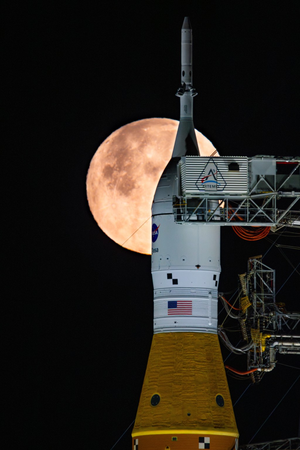
Artemis I is the first integrated test of NASA’s deep space exploration systems: the Orion spacecraft, Space Launch System (SLS) rocket and the ground systems at the agency’s Kennedy Space Center in Florida. The first in a series of increasingly complex missions, Artemis I is an uncrewed flight test that will provide a foundation for human deep space exploration and demonstrate our commitment and capability to return humans to the Moon and extend beyond.
- Launch site: Launch Pad 39B at NASA’s Kennedy Space Center in Florida
- Launch date: Nov. 16, 2022
- Launch time: 1:47 a.m. EST
- Mission Duration: 25 days, 10 hours, 53 minutes
- Destination: distant retrograde orbit around the Moon
- Total mission miles: approximately 1.4 million miles (2.3 million kilometers)
- Targeted splashdown site: Pacific Ocean, off the coast of San Diego
- Return speed: Up to 25,000 mph (40,000 kph)
- Splashdown: Dec. 11, 2022
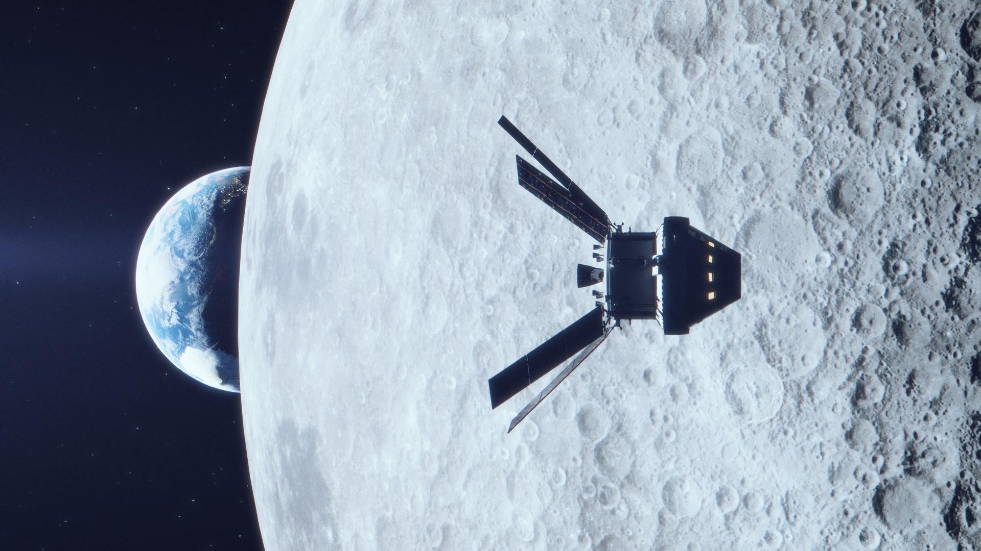
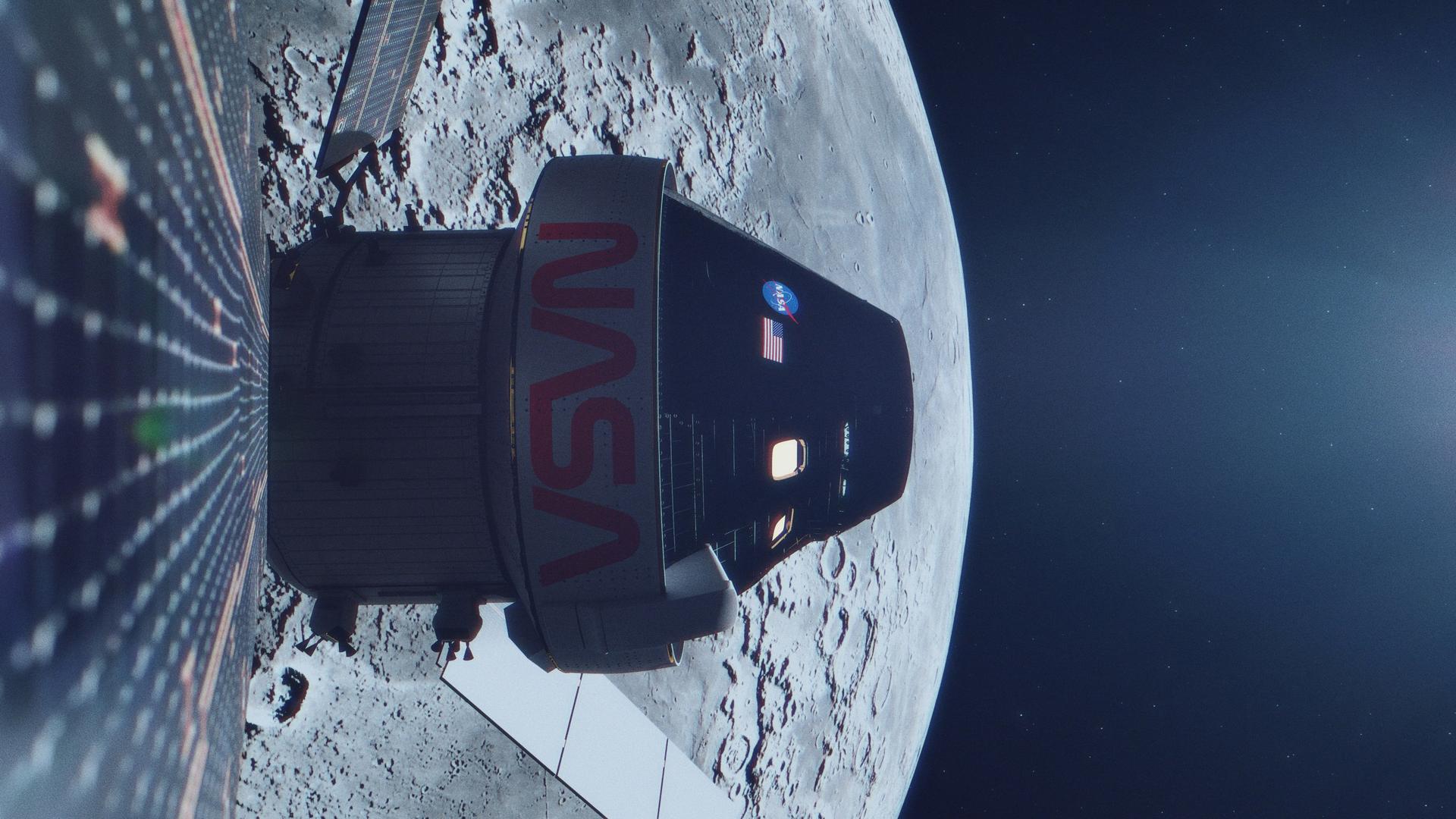
During this flight, Orion will launch atop the most powerful rocket in the world and fly farther than any spacecraft built for humans has ever flown. Over the course of the mission, it will travel 280,000 miles (450,000 kilometers) from Earth and 40,000 miles (64,000 kilometers) beyond the far side of the Moon. Orion will stay in space longer than any human spacecraft has without docking to a space station and return home faster and hotter than ever before.
This first Artemis mission will demonstrate the performance of both Orion and the SLS rocket and test our capabilities to orbit the Moon and return to Earth. The flight will pave the way for future missions to the lunar vicinity.
With Artemis I, NASA sets the stage for human exploration into deep space, where astronauts will build and begin testing the systems near the Moon needed for lunar surface missions and exploration to other destinations farther from Earth, including Mars. With Artemis, NASA will collaborate with industry and international partners to establish long-term exploration for the first time.
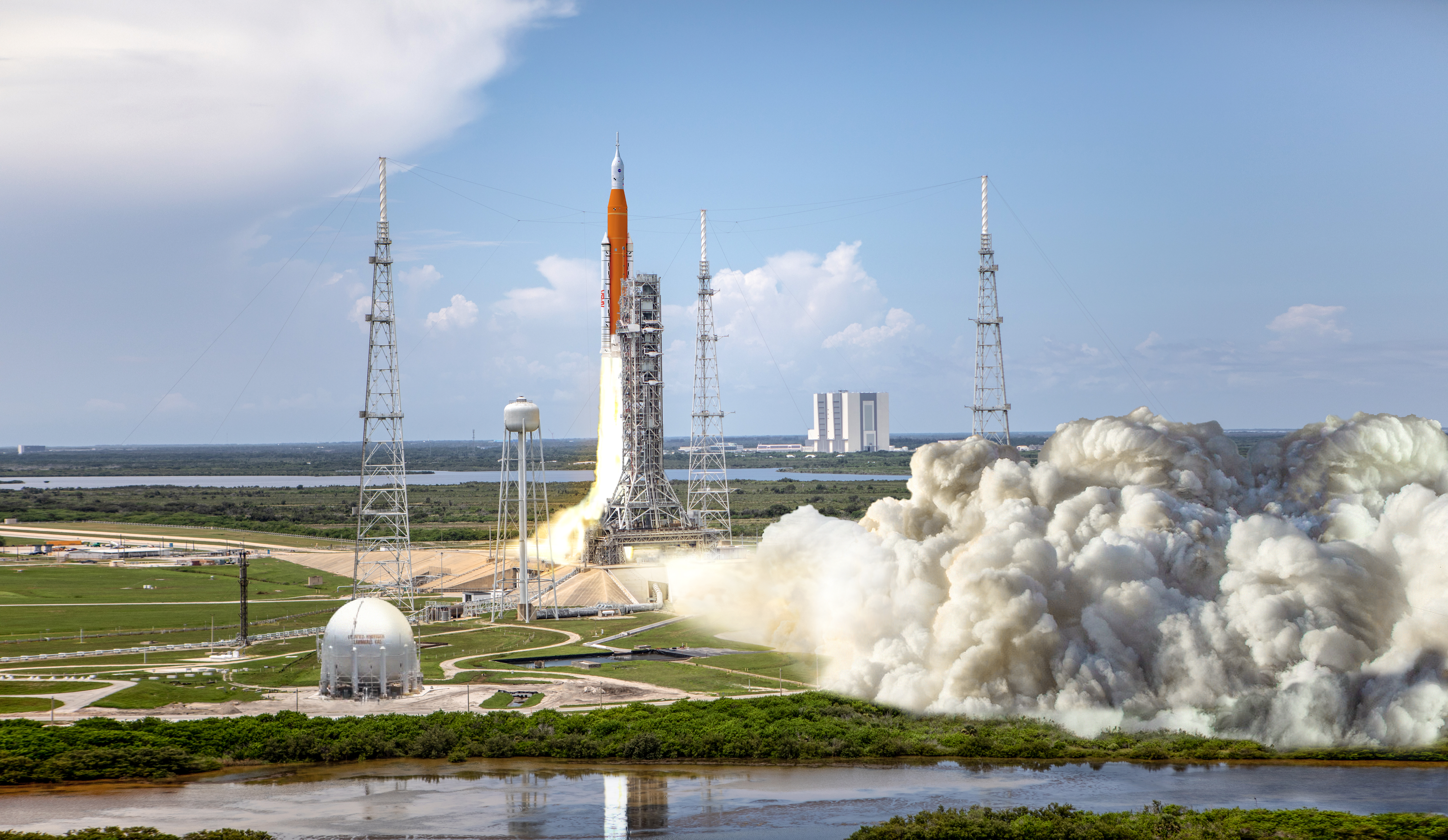
Launch
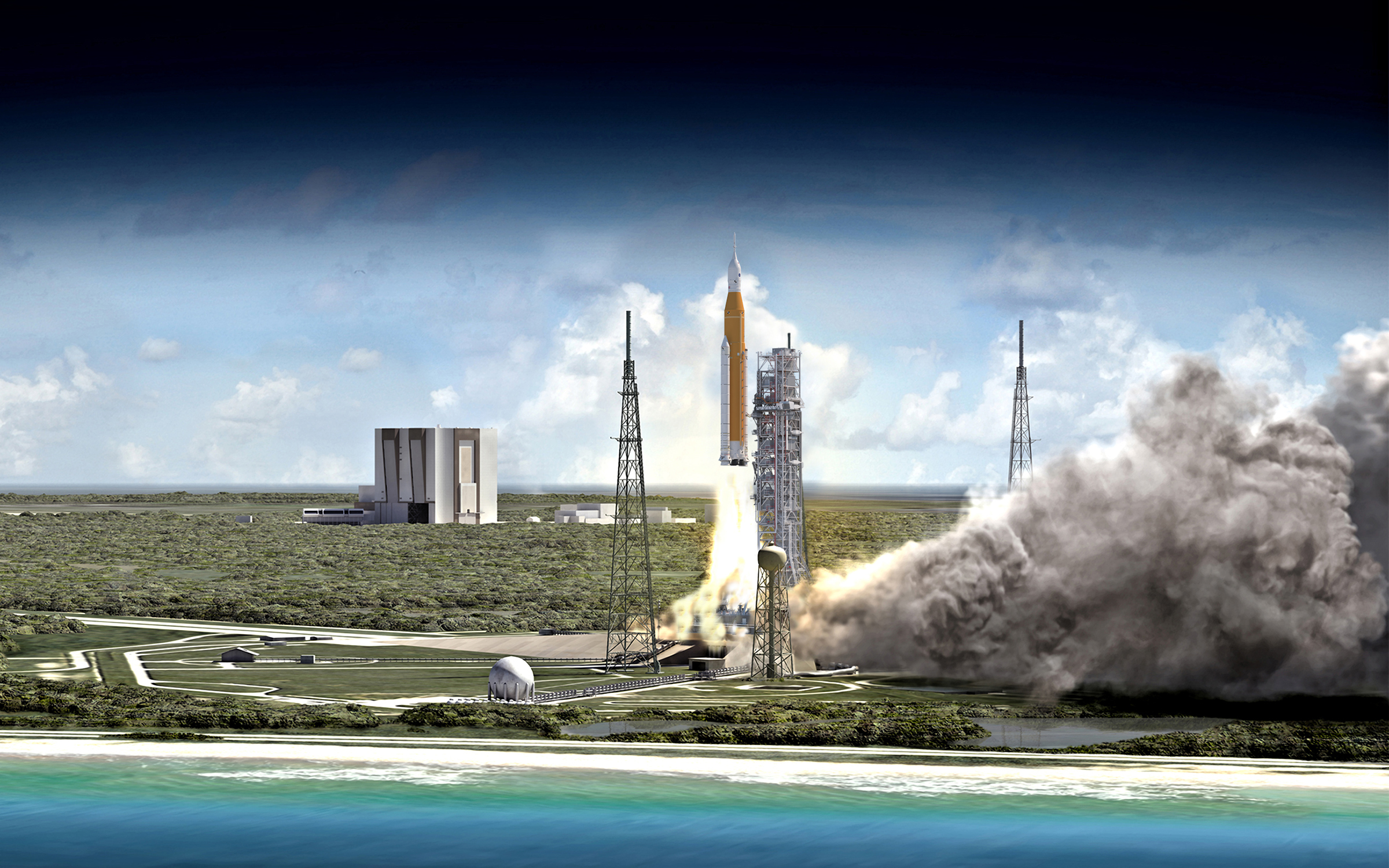
SLS and Orion will blast off from Launch Pad 39B at NASA’s modernized spaceport at Kennedy. Propelled by a pair of five-segment boosters and four RS-25 engines, the rocket will reach the period of greatest atmospheric force within 90 seconds. The solid rocket boosters will burn through their propellant and separate after approximately two minutes, and the core stage and RS-25s will deplete propellant after approximately eight minutes. After jettisoning the boosters, service module panels, and launch abort system, the core stage engines will shut down and the core stage will separate from the spacecraft, leaving Orion attached to the interim cryogenic propulsion stage (ICPS) that will propel it toward the Moon.
As the spacecraft makes an orbit of Earth and deploys its solar arrays, the ICPS will give Orion the big push it needs to leave Earth’s orbit and travel toward the Moon. This maneuver, known as the trans-lunar injection, precisely targets a point about the Moon that will guide Orion close enough to be captured by the Moon’s gravity.
In Space
Orion will separate from the ICPS approximately two hours after launch. The ICPS will then deploy ten small satellites, known as CubeSats, along the way to study the Moon or head father out to deep space destinations. As Orion continues on its path from Earth orbit to the Moon, it will be propelled by a service module provided by ESA (European Space Agency) that will course-correct as needed along the way. The service module supplies the spacecraft’s main propulsion system and power.
The outbound trip to the Moon will take several days, during which time engineers will evaluate the spacecraft’s systems. Orion will fly about 60 miles (97 kilometers) above the surface of the Moon at its closest approach, and then use the Moon’s gravitational force to propel Orion into a distant retrograde orbit, traveling about 40,000 miles (64,000 kilometers) past the Moon. This distance is 30,000 miles (48,000 kilometers) farther than the previous record set during Apollo 13 and the farthest in space any spacecraft built for humans has flown.
For its return trip to Earth, Orion will get another gravity assist from the Moon as it does a second close flyby, firing engines at precisely the right time to harness the Moon’s gravity and accelerate back toward Earth, setting itself on a trajectory to re-enter our planet’s atmosphere.
Landing
The mission will end with a test of Orion’s capability to return safely to Earth. Orion will enter Earth’s atmosphere traveling at about 25,000 mph (40,000 kph). Earth’s atmosphere will slow the spacecraft down to a speed of about 300 mph (480 kph), producing temperatures of approximately 5,000 degrees Fahrenheit (2,800 degrees Celsius) and testing the heat shield’s performance.
Once the spacecraft has passed this extreme heating phase of flight, the forward bay cover that protects its parachutes will be jettisoned. Orion’s two drogue parachutes deploy first, at 25,000 feet (7,600 meters), and within a minute slow Orion to about 100 mph (160 kph) before being released. They are followed by three pilot parachutes that pull out the three main parachutes which will slow Orion’s descent to less than 20 mph (32 kph). The spacecraft will make a precise landing within eyesight of the recovery ship off the coast of San Diego.
Recovery Operations
The Landing and Recovery Team, led by NASA’s Exploration Ground Systems program at Kennedy, will be responsible for safely recovering the capsule after splashdown. The interagency landing and recovery team consists of personnel and assets from the U.S. Department of Defense, including Navy amphibious specialists and Air Force weather specialists, and engineers and technicians from Kennedy, Johnson Space Center in Houston, and Lockheed Martin Space Operations.
Before splashdown, the team will head out to sea in a Navy ship. At the direction of the NASA Recovery Director, Navy divers and other team members in several inflatable boats will be cleared to approach Orion. Divers will then attach a cable to the spacecraft and pull it by winch into a specially designed cradle inside the ship’s well deck. The vessel will transport the spacecraft and other hardware to a pier at U.S. Naval Base San Diego for transport to Kennedy.
Open water personnel will also work to recover Orion’s forward bay cover and three main parachutes. If teams are able to recover the jettisoned cover and parachutes, engineers will inspect the hardware and gather additional performance data.
Major Mission Milestones
- Perigee Raise Maneuver – ICPS burn to raise Orion’s altitude at the point in the orbit where the spacecraft is nearest the Earth, known as its perigee, to ensure the spacecraft does not reenter the Earth’s atmosphere
- Trans-lunar Injection Burn – ICPS burn to increase Orion’s speed from 17,500 mph to 22,600 mph to escape the pull of Earth’s gravity for a precise trajectory to the Moon
- Outbound Powered Fly-by Burn – service module burn to send Orion close enough to the lunar surface to leverage the Moon’s gravitational force and direct the spacecraft toward entry into a lunar distant retrograde orbit
- Distant Retrograde Orbit Entry Burn – service module burn to enter lunar orbit and stabilize the spacecraft in the distant retrograde orbit
- Distant Retrograde Orbit Exit Burn – service module burn to exit lunar orbit and direct Orion to a second close lunar flyby
- Return Powered Fly-by Burn – service module burn to send Orion close enough to the lunar surface for a gravity assist from the Moon to slingshot Orion on a trajectory back to intercept the Earth’s atmosphere in preparation for reentry
- Entry and splashdown – the service module will separate from Orion just before re-entry, and the reaction control system engines will orient the crew module’s heat shield into the direction of travel to prepare for peak heating followed by a parachute assisted splashdown in the ocean.
- Passes Apollo 13 distance record – 248,654 miles (400,170 kilometers)
- Max distance from Earth – approximately 280,000 miles (450,000 kilometers)
Disposal of each of the major hardware elements follows a specific flight maneuver after launch with a carefully choreographed trajectory. Recovery systems have been omitted from SLS elements to launch heavier payloads, reduce operational costs, and power missions to the Moon and beyond that require maximum performance.
- The two solid rocket booters will fall into the Atlantic Ocean about 140 miles (225 km) off the Florida coast, north of the Bahamas.
- The core stage and launch vehicle stage adapter will fall into the Pacific Ocean east of Hawaii, west of Baja, California.
- After separating from NASA’s Orion spacecraft, the Interim Cryogenic Propulsion Stage will enter an orbit around the Sun.
- Near the end of the mission, Orion’s European Service Module will separate from the crew module prior to entering Earth’s atmosphere and burn up on re-entry over the Pacific Ocean.
The Artemis I trajectory is designed to ensure any remaining parts do not pose a hazard to land, people, or shipping lanes.
Mission Objectives
The primary objectives of the Artemis I flight test are to demonstrate the Orion heat shield at lunar return re-entry conditions, demonstrate operations and facilities during all mission phases, and retrieve the spacecraft after splashdown. In the course of completing these goals, the team aims to successfully demonstrate the SLS rocket’s capability, carry out the mission as planned, and ensure a safe return prior to the first flight with crew on Artemis II. Additional secondary objectives will be accomplished as possible throughout the mission that may support future development or mission planning efforts. These objectives will enable NASA to evaluate the performance of Orion, SLS, and the supporting ground systems for certification of the respective systems that will support future crewed missions.
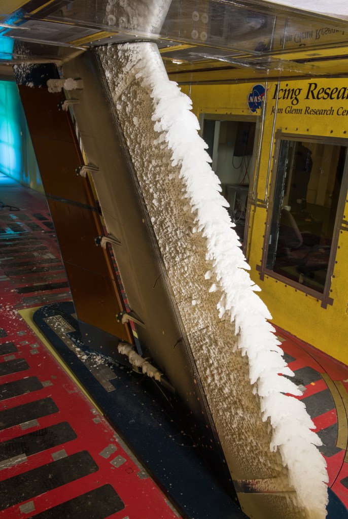
1 – Demonstrate Orion’s heat shield can withstand the high speed and high heat conditions when returning through Earth’s atmosphere from lunar velocities
When Orion returns from the Moon, it will be traveling nearly 25,000 mph (40,000 kph) and experience temperatures up to 5,000 degrees Fahrenheit (2,800 degrees Celsius) as it enters Earth’s atmosphere, much faster and hotter than a return from low-Earth orbit. While the heat shield has undergone extensive testing on Earth and was demonstrated on Exploration Flight Test-1 in 2014, no aerodynamic or aerothermal test facility can recreate the conditions the heat shield will experience returning at lunar return speeds. Validating heat shield performance is required before crews fly in Orion.
2 – Demonstrate operations and facilities during all mission phases
From launch countdown through recovery of Orion from the Pacific Ocean at the end of its mission, Artemis I provides an opportunity to test many aspects of NASA’s launch facilities and ground-based infrastructure, SLS operations, including separation events during ascent, Orion operations in space, and recovery procedures. During the flight, engineers will verify systems such as the spacecraft’s communications, propulsion, and navigation systems. Operating Orion in space will give engineers further confidence the spacecraft can tolerate the extreme thermal environment of deep space and successfully pass through the Van Allen Radiation Belt, that Orion’s main engine and solar array wings work as designed, and the flight operations teams can successfully manage and execute the mission, as well as demonstrate the performance of support systems for NASA facilities needed during the flight.
3 – Retrieve Orion after splashdown
While engineers will receive data throughout the flight, retrieving the crew module after splashdown will provide information to engineers to inform future missions. Once returned to Kennedy after the mission, technicians will conduct detailed inspections of Orion, retrieve data recorded on board during the flight, reuse components such as avionics systems, and retrieve information from payloads. It will also allow NASA to demonstrate its recovery techniques and procedures, which are critical to the safe return of future crews.
4 – Accomplish additional flight test objectives
A number of additional objectives will demonstrate other capabilities and aspects of the rocket, spacecraft, integrated systems, and recovery plans. Some of these flight test objectives include certifying Orion’s optical navigation system, deploying the 10 CubeSats riding inside the Orion stage adapter, operating the technology and biology payloads onboard Orion, and collecting imagery throughout the mission.
Countdown Timeline
Before the Artemis I mission launches on its way around the Moon, the launch team at Kennedy and supporting teams across the country will begin the launch countdown about two days before liftoff.
The launch countdown contains “L Minus” and “T Minus” times. “L minus” indicates how far away liftoff is in hours and minutes and does not include built-in holds. “T minus” time is a sequence of events that are built into the launch countdown where counting and holds are inserted.
Pauses in the countdown, or “holds,” are built into the countdown to allow the launch team to target a precise launch window, and to provide a cushion of time for certain tasks and procedures without impacting the overall schedule. For the Artemis I countdown, planned built-in holds vary in length and occur at the following times: L-8 hours 40 minutes, and L-40 minutes.
These key events will take place during the countdown.
L-47 hours 40 minutes and counting
- The launch team arrives on their stations and the countdown begins (L-47, 40 minutes hours)
- The countdown clock begins (L-47H10M)
- Fill the water tank for the sound suppression system (L-47H – L-42H)
- Liquid Oxygen (LOX)/Liquid Hydrogen (LH2) system preparations for vehicle loading (L-47H – L-38H)
- The Orion spacecraft is powered up if not already powered at call to stations (L-43H – L-41H30M)
- The interim cryogenic propulsion stage (ICPS) is powered-up (L-39H30M – L-36H30M)
- The core stage is powered up (L-38H – L-37H20M)
- Final preparations of the four RS-25 engines (L-37H20M – L-32H)
L-32 hours and counting
- Core stage composite overwrapped pressure vessel (COPV) Pressurization to Flight Pressure (L-32H – L-23H)
- The ICPS is powered down (L-31H – L-30H30M)
- Charge Orion flight batteries to 100% (L-31H – L-27H)
- Charge core stage flight batteries (L-28H – L-22H)
- The ICPS is powered-up for launch (L-19H30M – L-16H30M)
L-15 hours and counting
- All non-essential personnel leave Launch Complex 39B (L-13H – L-11H)
- Ground Launch Sequencer (GLS) activation (L-11H15M – 10H15M)
- Air-to-gaseous nitrogen (GN2) changeover and vehicle cavity inerting (L-11H45M – launch)
L-10 hours, 40 minutes and counting
- 3.5-hour built in countdown hold begins (L-10H40M – L-7H10M)
- Launch team conducts a weather and tanking briefing (L-10H40M – L-9H50M)
- Launch team decides if they are “go” or “no-go” to begin tanking the rocket (L-9H40M)
- Core stage LOX transfer line chilldown (L-9H15M – L-9H)
- Core stage LH2 transfer line chilldown (L-9H15M – L-8H45M)
L-8 hours and counting
- Core stage LOX main propulsion system chilldown (L-9H – L-8H20M)
- Core stage LH2 slow fill start (L-8H45M – L-7H50M)
- Core stage LOX slow fill (L-8H20M – L-8H5M)
- Core stage LOX fast fill (L-8H5M – L-5H15M)
- Core stage LH2 fast fill (L-7H50M – L-6H10M)
- Engine bleed kick start (L-7H40M – L-7H20M)
- Core stage LH2 topping (L-6H10M – L6H5M)
- Core stage LH2 replenish (L-6H5M – launch)
- Core stage LOX topping (L-5H15M– L-5H5M)
- ICPS LH2 ground support equipment and tank chilldown (L-5H20M – L-5H)
L-5 hours and counting
- Core stage LOX replenish (L-5H5M – launch)
- ICPS LOX main propulsion system chilldown (L-5H5M– L-4H45M)
- ICPS LH2 fast fill start (L-5H5M – L4H5M)
- Orion communications system activated (RF to Mission Control) (L-4H20M – L-3H45M)
- ICPS LOX fast fill (L-4H55M– L-4H10M)
- ICPS LOX validation and leak test (L-4H10M – L-3H40M)
- ICPS LH2 validation and leak test (L-4H – L-3H40M)
- ICPS LH2 tank topping start (L-3H40M – L-3H25M)
- ICPS LH2 replenish (L-3H25M – launch)
- ICPS LOX topping (L-3H40M – L-3H20M)
- ICPS LOX replenish (L-3H20M – launch)
- ICPS/Space Launch System (SLS) telemetry data verified with Mission Control Center and SLS Engineering Support Center (L-3H – L-2H50M)
L-50 minutes and counting
- Final NASA Test Director briefing is held (L-50M)
L-40 minutes and holding
- Built in 30-minute countdown hold begins (L-40M)
L-15 minutes and holding
- The launch director polls the team to ensure they are “go” for launch
T-10 minutes and counting
- Ground Launch Sequencer (GLS) initiates terminal count (T-10M)
- GLS go for core stage tank pressurization (T-6M)
- Orion ascent pyros are armed (T-6M)
- Orion set to internal power (T-6M)
- Core stage LH2 terminate replenish (T-5M57S)
- GLS is go for flight termination system (FTS) arm (T-5M)
- GLS is go for LH2 high flow bleed check (T-4M40S)
- GLS is go for core stage auxiliary power unit (APU) start (T-4M)
- Core Stage APU starts (T-4M)
- Core stage LOX terminate replenish (T-4M)
- ICPS LOX terminate replenish (T-3M30S)
- GLS is go for purge sequence 4 (T-3M10S)
- ICPS switches to internal battery power (T-1M56S)
- Core stage switches to internal power (T-1M30S)
- ICPS enters terminal countdown mode (T-1M20S)
- ICPS LH2 terminate replenish (T-50S)
- GLS sends “go for automated launch sequencer” command (T-33S)
- Core stage flight computer to automated launching sequencer (T-30S)
- Hydrogen burn off igniters initiated (T-12S)
- GLS sends the command for core stage engine start (T-10S)
- RS-25 engines startup (T-6.36S)
T-0
- Booster ignition, umbilical separation, and liftoff
Inside the terminal countdown, teams have a few options to hold the count if needed.
- The launch team can hold at 6 minutes for the duration of the launch window, less the 6 minutes needed to launch, without having to recycle back to 10 minutes.
- If teams need to stop the clock between T-6 minutes and T-1 minute, 30 seconds, they can hold for up to 3 minutes and resume the clock to launch. If they require more than 3 minutes of hold time, the countdown would recycle back to T-10.
- If the clock stops after T-1 minute and 30 seconds, but before the automated launch sequencer takes over, then teams can recycle back to T-10 to try again, provided there is adequate launch window remaining.
- After handover to the automated launch sequencer, any issue that would stop the countdown would lead to concluding the launch attempt for that day.
Ascent & Mission Timeline
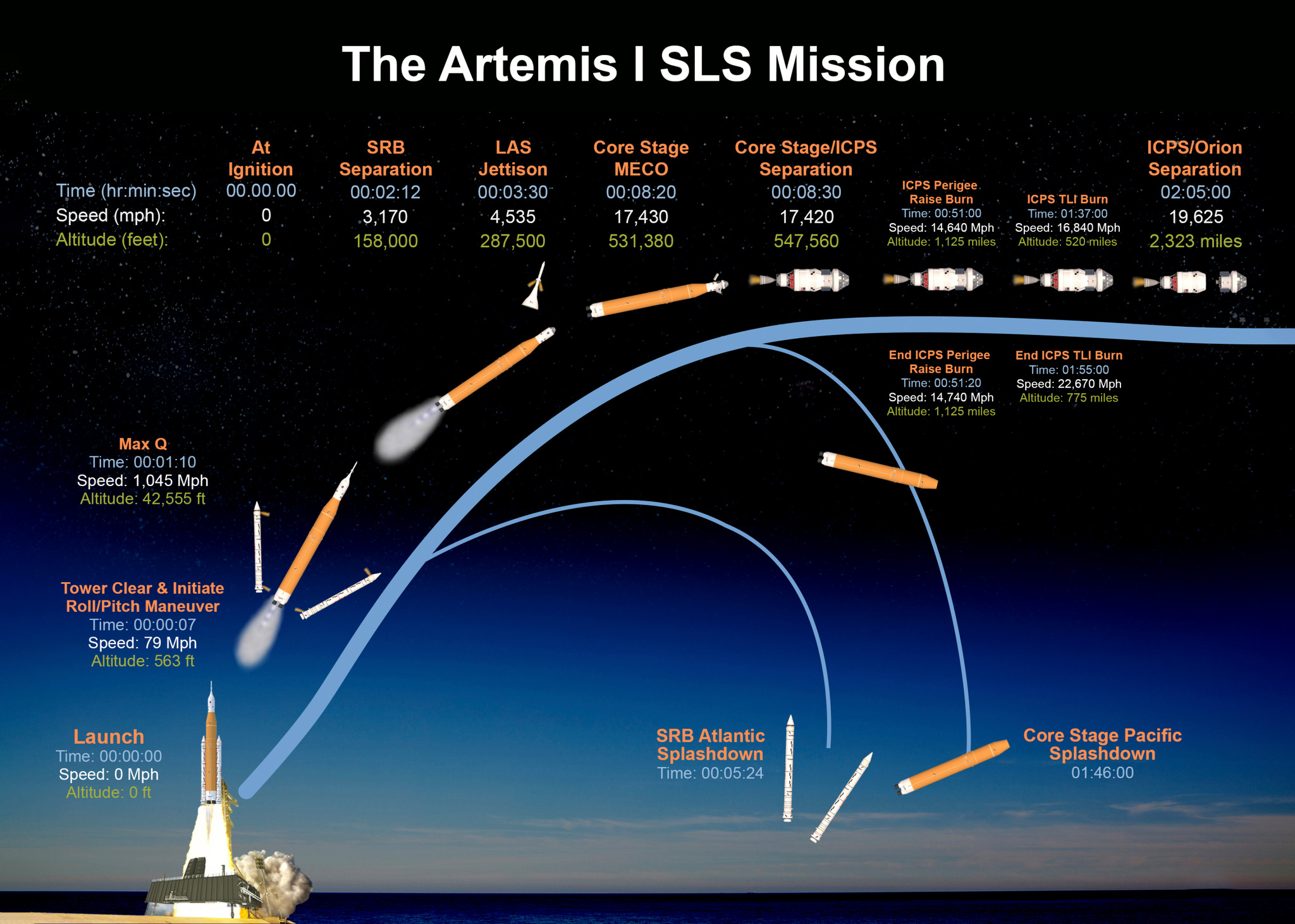
Times below are based on a launch at Nov. 16 at 1:04 a.m. Eastern. The timing of events may change if launch occurs at a time other than the opening of the launch window. All times Eastern.
Flight Day 1
1:04 a.m. – Liftoff
1:06:12 a.m. – Solid Rocket Booster separation (Mission Elapsed Time 00:02:12)
1:07:11 a.m. – Service module fairing jettison (MET 00:03:11)
1:07:16 a.m. – Launch abort system jettison (MET 00:03:16)
1:12:03 a.m. – Core stage main engine cutoff commanded (MET 00:08:03)
1:12:15 a.m. – Core Stage/ICPS separation (MET 00:08:15)
1:22:09 a.m. – Orion Solar Array Wing Deploy Begins (MET 00:18:09)
- Approximately 12 minutes in duration
1:56:56 a.m. – Perigee Raise Maneuver (MET 00:52:56)
- 22 seconds in duration
2:33:27 a.m. – Trans-lunar injection (MET 01:29:27)
- Approximately 18 minute burn
3:01:36 a.m. – Orion/ICPS separation (MET 01:57:36)
3:02:58 a.m. – Upper Stage Separation Burn (MET 01:58:58)
4:25:36 a.m. – ICPS Disposal Burn (MET 03:21:36)
8:51:31 a.m. – Outbound Trajectory Correction-1 burn (MET 07:47:31)
- First service module burn
Flight Day 2-5 – Outbound transit
Flight day 6-9 – Transit to Distant Retrograde Orbit (DRO) around the Moon
- Flight Day 6 (11/21): Outbound Powered Fly-by (burn 7:44 a.m.), Lunar close approach (~81.1 miles, 130 km)
Flight Day 10-15 – In DRO
- Flight Day 10 (11/25): DRO Insertion (burn 4:52 p.m.)
- Flight Day 11 (11/26): Orion passes Apollo 13 Record of 248,655 miles (400,171 km) from Earth for a spacecraft designed for humans (8:42 a.m.)
- Flight Day 13: (11/28): Orion reaches maximum distance from Earth (4:05 p.m.) at approximately 268,563 miles (432,194 km)
Flight Day 16-19 – Exit DRO
- Flight Day 16 (12/1): DRO Departure (burn 4:53 p.m.)
Flight Day 20-26 – Return transit
- Flight Day 20 (12/5): Return Flyby (burn 11:43 a.m.), Lunar close approach (~79.2 miles, 128 km)
Flight Day 26 – Earth Return
- 12:00:10 p.m. – Crew Module/Service Module Separation
- 12:20:14 p.m. – Crew Module Entry Interface
- 12:35:28 p.m. – Altitude 40K
- 12:36:02 p.m. – FBC Chute Deploy
- 12:36:04 p.m. – FBC Jettison
- 12:36:06 p.m. – Drogue Chute Deploy
- 12:37:26 p.m. – Main Chute Deploy
- 12:37:26 p.m. – Drogue Chute Jettison
- 12:39:41 p.m. – Splashdown
Weather Criteria
The weather guidelines for Artemis I identify each condition that must be met to safely roll out to the pad and launch.
These guidelines include criteria for various meteorological conditions. Weather teams refer to these criteria while monitoring the elements and implement constraints when conditions could affect rollout or liftoff.
If other potential weather hazards exist beyond those in the guidelines, the launch weather team will report the hazardous condition to the launch director, who will determine whether launching would expose Artemis I to a weather hazard.
BASIC WEATHER CRITERIA FOR ROLL TO THE PAD
Do not roll to launch pad if the lightning forecast is greater than 10% within 20 nautical miles of the launch area during rollout.
Do not roll to launch pad if there is greater than a 5% chance of hail forecast in the launch area during rollout.
Do not roll to launch pad if the peak winds exceed 40 knots in the launch area during rollout.
Do not roll to launch pad if temperature is less than 40 degrees Fahrenheit or exceeds 95 degrees Fahrenheit at the launch area during rollout.
BASIC WEATHER LAUNCH CRITERIA AT THE PAD FOR LIFTOFF
TEMPERATURE
Do not initiate tanking if the 24-hour average temperature at both 132.5 feet and 257.5 feet is less than 41.4 degrees Fahrenheit.
Do not launch if the temperature at both 132.5 feet and 257.5 feet exceeds 94.5 degrees Fahrenheit for 30 consecutive minutes.
Do not launch if the temperature at both 132.5 feet and 257.5 feet drops below a defined temperature constraint for 30 consecutive minutes. The temperature constraints range from 38 degrees Fahrenheit to 49 degrees Fahrenheit, depending upon the wind and relative humidity. Higher wind and relative humidity result in a colder temperature constraint.
WIND
Do not launch if the peak liftoff winds exceed a range of 29 knots through 39 knots between 132.5 feet and 457.5 feet, respectively.
Do not launch through upper-level wind conditions that could lead to control problems for the launch vehicle.
PRECIPITATION
Do not launch through precipitation.
LIGHTNING
Do not initiate tanking of the core stage or interim cryogenic propulsion stage (ICPS) if the lightning forecast is greater than 20% within 5 nautical miles of the launch area during tanking.
Do not launch for 30 minutes after lightning is observed within 10 nautical miles of the flight path, unless specified conditions related to cloud distance and surface electrical fields can be met.
Do not launch if the flight path is within 10 nautical miles of the edge of a thunderstorm that is producing lightning until 30 minutes after the last lightning discharge is observed.
Do not launch if the flight path is within 10 nautical miles of an attached thunderstorm anvil cloud unless temperature, time since last lightning, and distance criteria can be met, and if within 3 nautical miles, maximum radar reflectivity criteria also are satisfied.
Do not launch if the flight path is within 10 nautical miles of a detached thunderstorm anvil cloud unless temperature, time since lightning and/or detachment, and distance criteria can be met, and if within 3 nautical miles, maximum radar reflectivity criteria also are satisfied.
CLOUDS
Do not launch if the flight path is within 3 nautical miles of a thunderstorm debris cloud for 3 hours, unless temperature, surface electric field, and radar reflectivity criteria can be met.
Do not launch if the flight path is within 5 nautical miles of disturbed weather clouds that extend into freezing temperatures and contain moderate or greater precipitation.
Do not launch through a cloud layer that is within 5 nautical miles, greater than 4,500 feet thick, and extends into freezing temperatures, unless specific criteria related to radar reflectivity and cloud altitude can be met.
Do not launch if the flight path is within 10 nautical miles of cumulus clouds with certain distance and height criteria. There are additional caveats that could be met for clouds not reaching 23 degrees Fahrenheit.
Do not launch through cumulus clouds formed as the result of or directly attached to a smoke plume, unless more than 60 minutes passed since detachment from the smoke plume.
Do not launch for 15 minutes if field mill instrument readings within 5 nautical miles of the launch pad equal or exceed +/- 1,500 volts per meter, or +/- 1,000 volts per meter, unless specific caveats related to clouds within 10 nautical miles of the flight path can be met.
SOLAR ACTIVITY
Do not launch during active solar activity resulting in increased density of solar energetic particles.
What’s On Board
Artemis I will carry several payloads aboard SLS and Orion, including a number of technology demonstrations and science investigations, as well as mementos to be returned to Earth in Orion.
CubeSats
Small, low-cost science and technology experiments called CubeSats will deploy into deep space from the Orion stage adapter attached to the ICPS. These CubeSats are not much larger than a shoebox, weigh about 25 pounds (11 kilograms) each, and contain science and technology that may help pave the way for future human exploration in deep space. International space agency partners and universities are involved with several of the CubeSats.
Artemis I CubeSats are listed below with their provider, area of exploration:
Moon
Lunar IceCube – Morehead State University, Morehead, Kentucky
Searching for water in all forms and other volatiles with an infrared spectrometer
LunaH-Map – Arizona State University, Tempe, Arizona
Creating higher-fidelity maps of near-surface hydrogen in craters and other permanently shadowed regions of the lunar South Pole with neutron spectrometers
LunIR – Lockheed Martin, Denver, Colorado
Performing advanced infrared imaging of the lunar surface
OMOTENASHI – JAXA, Japan
Developing the world’s smallest lunar lander and studying the lunar environment
Radiation
CuSP – Southwest Research Institute, San Antonio, Texas
Measuring particles and magnetic fields as a space weather station
BioSentinel – Ames Research Center, Silicon Valley, California
Using single-celled yeast to detect, measure and compare the impact of deep-space radiation on living organisms over a long period of time
EQUULEUS – University of Tokyo/JAXA, Japan
Imaging the Earth’s plasmasphere for a better understanding of Earth’s radiation environment from Earth-Moon LaGrange 2 point
Asteroid
NEA Scout – Marshall Space Flight Center, Huntsville, Alabama
Traveling by solar sail to a near-Earth asteroid and taking pictures and other characterizations of its surface
Technology Demonstrations
ArgoMoon – Italian Space Agency (ASI), ArgoTec, Italy
Observing the interim cryogenic propulsion stage with advanced optics and software imaging system
Team Miles – Tampa, Florida
Demonstrating propulsion using plasma thrusters and competing in NASA’s Deep Space Derby
Purposeful Passengers
Three “passengers” will fly aboard Orion to test the spacecraft’s systems and collect data to inform future missions with astronauts.
Commander Moonikin Campos
A suited manikin named Commander Moonikin Campos during a public contest will occupy the commander’s seat inside Orion to provide data on what crew members may experience in flight.
The manikin’s seat will be outfitted with two sensors – one under the headrest and another behind the seat – to record acceleration and vibration throughout the mission. Five additional accelerometers inside Orion will provide data to compare vibration and acceleration between the upper and lower seats. The Orion Crew Survival System suit – a spacesuit astronauts will wear during launch, entry, and other dynamic phases of their missions – worn by the manikin will also be equipped with two radiation sensors.
Helga and Zohar
Two additional seats in Orion will be occupied by manikin torsos, called phantoms, manufactured from materials that mimic human bones, soft tissues, and organs of an adult female. Named Zohar and Helga, the torsos will be fitted with more than 5,600 passive sensors and 34 active radiation detectors to measure radiation exposure as part of the Matroshka AstroRad Radiation Experiment (MARE), an international effort including the German Aerospace Center, the Israel Space Agency, and NASA.
Zohar will wear a radiation protection vest, called AstroRad, while Helga will not. The study will provide valuable data on radiation levels astronauts may encounter on lunar missions and evaluate the effectiveness of the protective vest that could allow crew to exit the storm shelter and continue working on critical mission activities in spite of a solar storm.
Additional Radiation Sensors
In addition to the CubeSats aboard the SLS rocket and the manikins inside the spacecraft, Orion will carry several additional instruments and investigations to study the radiation environment of deep space that is present for missions to the Moon and beyond.
Radiation Area Monitor (RAM)
Radiation sensor technology aboard the spacecraft includes six Radiation Area Monitor (RAM) passive detectors about the size of a matchbox that will record the total radiation dose during the mission. As passive instruments, they require no source of power to collect radiation dose information and will be analyzed after the flight.
Hybrid Electronic Radiation Assessor (HERA)
Orion also will be equipped with a radiation detector named the Hybrid Electronic Radiation Assessor (HERA) that will measure charged particles that pass through its sensors. As an active instrument attached to the spacecraft, it will be connected to power and also can send its readings to Earth during the flight. On crewed missions, HERA will be part of the spacecraft’s Caution and Warning System and will sound a warning in the case of a solar energetic particle event, notifying the crew to take shelter. NASA is also testing a similar HERA unit aboard the International Space Station.
ESA Active Dosimeters
Created and provided by ESA, five devices each about the size of a deck of cards will be mounted inside the cabin and equipped with multiple sensors that cover a broad range of energies from ionizing radiation in space. Called ESA Active Dosimeters, the devices will record data on the radiation environment inside the spacecraft in real time with a timestamp to allow scientists to see radiation dose rates during various mission phases, as well as total mission dose. Scientists tested a similar ESA active dosimeter on the space station.
Biology Investigations
Orion will also carry a payload called Biological Experiment-01 containing four space biology investigations. These investigations will look at the effects of the deep space environment on the nutritional value of seeds, DNA repair of fungi, adaptation of yeast, and gene expression of algae during the journey around the Moon. The experiments will take place inside a container stored within Orion’s crew module for the duration of Artemis I and will be returned to researchers for post-flight analyses after the spacecraft splashes down. The fundamental knowledge gained from these investigations will help us learn how we can better thrive in deep space, for future missions to the Moon and Mars.
Callisto
Callisto is a technology demonstration developed through a reimbursable space act agreement with Lockheed Martin. Lockheed Martin has partnered with Amazon, and Cisco to bring the Alexa digital assistant and Webex video collaboration aboard Orion’s first flight test in deep space.
Named after a mythological Greek goddess and one of Artemis’ hunting attendants, Callisto is meant to show how commercial technology could assist future astronauts on deep space missions. The payload will demonstrate how astronauts and flight controllers can use human-machine interface technology to make their jobs simpler, safer and more efficient, and advance human exploration in deep space.
The industry-funded payload will be located on Orion’s center console and includes a tablet that will test Webex by Cisco video conferencing software to transmit video and audio from the Mission Control Center at Johnson, and custom-built hardware and software by Lockheed Martin and Amazon that will test Alexa, Amazon’s voice-based virtual assistant, to respond to the transmitted audio.
Deep Space Exploration System
The Space Launch System rocket, Orion spacecraft, and ground systems at Kennedy Space Center in Florida are critical to NASA’s exploration plans at the Moon and beyond. NASA designed the SLS as the world’s most powerful rocket for safely sending humans on missions to deep space, and Orion is specifically designed to sustain humans hundreds of thousands of miles from home. Exploration Ground Systems (EGS) at Kennedy has the infrastructure to support the systems and facilities necessary to process and launch SLS and Orion. Together, SLS, Orion, and EGS are designed to meet the evolving needs of our nation’s deep space exploration program for decades to come.
Orion
The Orion spacecraft is specifically designed to carry astronauts to deep space and is currently the only spacecraft capable of crewed deep space flight and high-speed return from the vicinity of the Moon. Orion is composed of three main elements and supporting subsystems. The main elements are 1) the crew module, where astronauts live and work; 2) the service module, provided by ESA, which will provide power, propulsion, and thermal control; and 3) the launch abort system, which can pull the spacecraft and crew to safety in the event of an emergency during launch or ascent to orbit.
On deep space missions, both distance and duration dictate the capabilities and advanced technologies needed. Artemis I will test Orion’s navigation and communications systems beyond the range of GPS and above communication satellites in Earth orbit; test the radiation sensors and shielding outside the protection of Earth’s magnetic field; and test the world’s largest heat shield during a high-speed return from the Moon, at nearly 25,000 mph and temperatures half as hot as the surface of the Sun.
Space Launch System (SLS)
NASA’s Space Launch System (SLS) is the world’s most powerful rocket that provides the foundation for human exploration beyond Earth’s orbit and is currently the only rocket that can safely send Orion directly to the Moon. The main elements are 1) a central core stage that houses propellant tanks, engines, and avionics; 2) four liquid propellant RS-25 engines powered by cryogenic, or supercold, liquid hydrogen and liquid oxygen; 3) two solid-fuel rocket boosters that provide the majority of thrust and steering for the rocket during the first two minutes of flight; and 4) an upper stage fueled by liquid hydrogen and liquid oxygen for in-space propulsion after separation from the core stage.
SLS is designed specifically for deep space missions with humans and will send the Orion spacecraft to the Moon, which is nearly 1,000 times farther than where the International Space Station resides in low-Earth orbit. The rocket will provide the power to help Orion reach a speed of 22,600 mph, to escape the pull of Earth’s gravity send the spacecraft to the Moon.
Exploration Ground Systems
The role of the Exploration Ground Systems (EGS) Program is to develop and operate the systems and facilities necessary to process, assemble, transport, and launch rockets and spacecraft at the NASA’s Kennedy Space Center in Florida. For Artemis missions, EGS is focused on the equipment, management, and operations required to safely connect the Orion spacecraft with the SLS rocket; move the rocket to the launch pad; successfully launch it into space; and recover the spacecraft once it has splashed down.
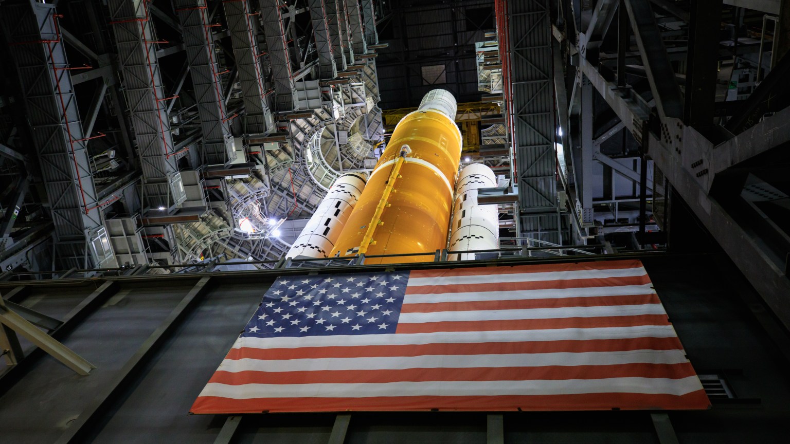
The main elements at Launch Complex 39 consist of 1) the 52-story Vehicle Assembly Building (VAB) for final assembly and testing of the rocket and spacecraft; 2) the mobile launcher that serves as the ground structure for stacking the rocket and spacecraft inside the VAB and from which the rocket will launch on the pad; 3) the crawler-transporter that will carry the rocket and spacecraft atop the mobile launcher along a crawlerway between the VAB and the pad; 4) the Launch Control Center, which contains the firing rooms for commanding the launch; and 5) Launch Pad 39B with electrical power, a water system, a flame trench, and a safe launch area to support SLS launches.
Space Communications & Navigation
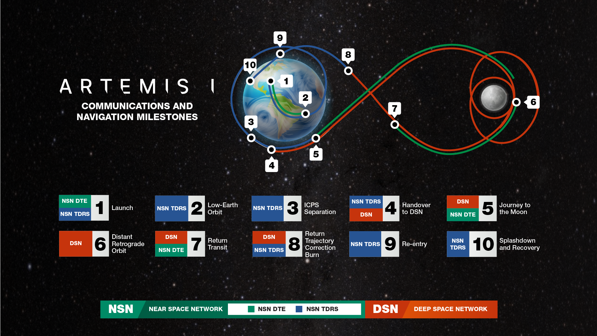
Artemis I will demonstrate NASA’s comprehensive communications network services for journeys to lunar orbit. The mission relies on NASA’s worldwide network infrastructure for seamless communications, providing different service levels as Orion leaves Earth, orbits the Moon, and returns safely home.
For Artemis I, NASA’s Near Space Network and NASA’s Deep Space Network will be used to support communication and navigation services. Communication services allow flight controllers to send commands to the spacecraft and receive data from Orion, the Space Launch System, and the rocket’s upper stage. Navigation, or tracking, services enable the flight controllers to calculate where the spacecraft are along their trajectory through space.
NASA’s Near Space Network
NASA’s Near Space Network provides a suite of communications and navigation services through commercial and government-owned, contractor-operated network infrastructure. The network will provide communications and navigation services during launch and navigation services at various points on the journey to the Moon. Additionally, as Orion journeys back to Earth, the Near Space Network will provide communications and navigation services.
The Near Space Network’s Launch Communications Segment will provide links to both Orion and SLS during prelaunch and launch for Artemis I. NASA’s constellation of Tracking and Data Relay Satellites (TDRS) will provide near-continuous communications services during launch and low-Earth orbit phases of the Artemis I mission. TDRS will continue service until Orion and ICPS leave its coverage volume, when NASA’s Deep Space Network takes over, and then provide service again on Orion’s return to Earth, from the final return trajectory correction burn through splashdown.
NASA’s Deep Space Network
The Deep Space Network will handle communications beyond low-Earth orbit. Additionally, the network will facilitate communications during the CubeSat deployments that will fly as secondary payloads on Artemis I with their own science and technology missions. The Near Space Network and Deep Space Network will work together to support navigation for Orion so that engineers can employ a technique called three-way Doppler tracking. With two ground stations on Earth in contact with Orion simultaneously – one from each network – NASA can triangulate Orion’s location relative to the ground stations.
Flight Facilities

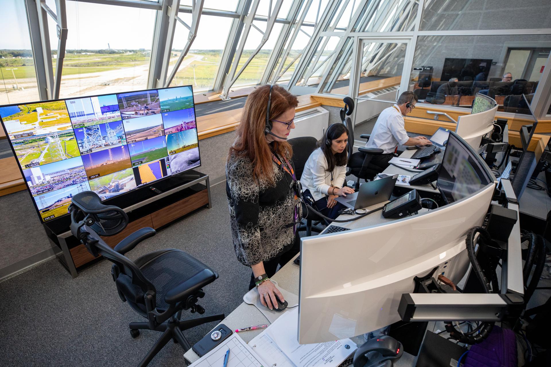
Launch Control Center
The Launch Control Center (LCC) at NASA’s Kennedy Space Center in Florida is where launch operations personnel will operate, monitor, and coordinate the launch of the SLS rocket and Orion spacecraft.
The LCC links the launch team operators inside Firing Room 1 to the SLS rocket and Orion spacecraft in processing areas such as the Vehicle Assembly Building, mobile launcher, and at Launch Complex 39B. Controllers at Kennedy are also able to communicate with controllers at the Space Launch Delta 45 Eastern Range and other NASA control centers from the LCC.
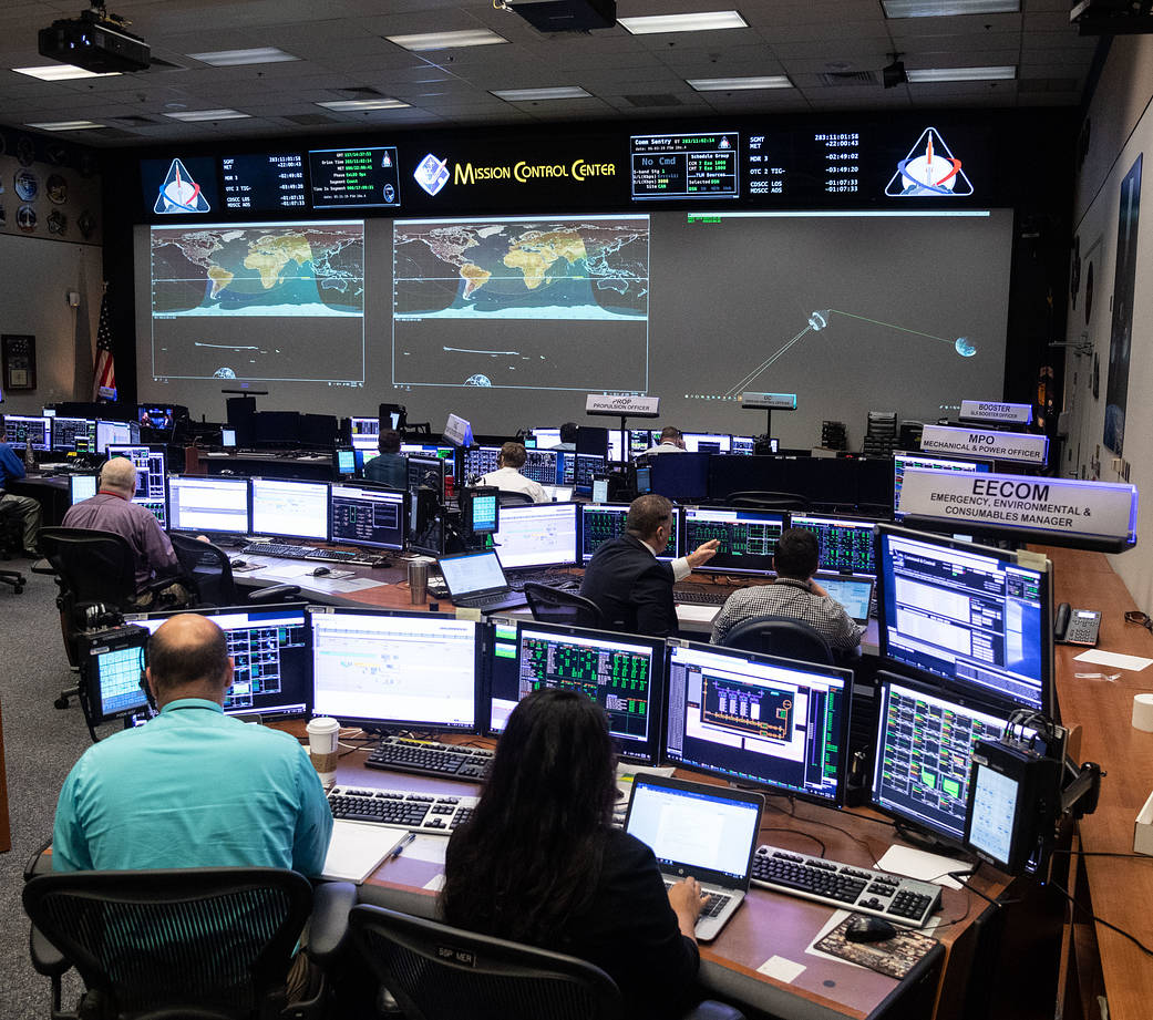
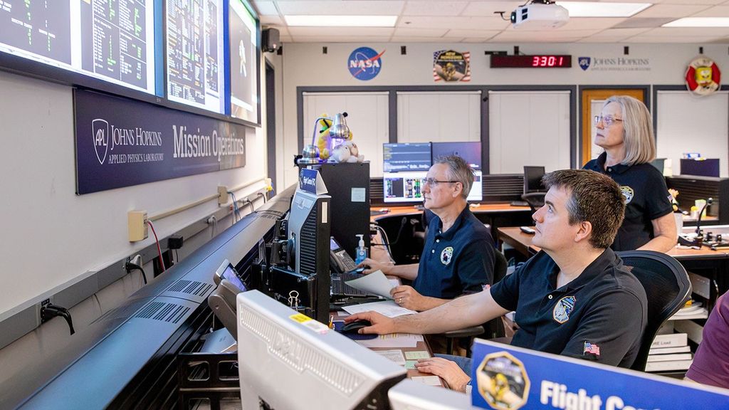
Mission Control Center
NASA’s Christopher C. Kraft Jr. Mission Control Center (MCC) at the Johnson Space Center in Houston is the facility from which flight operations personnel will remotely monitor and operate the Orion spacecraft and receive data from Orion and SLS.
MCC is comprised of several flight control rooms (FCR), including FCR-1, FCR-2 (the historic Apollo Flight Control Room) and the Red, White, and Blue FCRs. The White FCR was transformed from its shuttle legacy configuration into a modern mission control configuration known as the MCC-21 effort and is ultimately intended to serve as the mission control for flights of NASA’s Orion spacecraft on missions to deep space destinations.
SLS Engineering Support Center
The SLS Engineering Support Center is located in the Huntsville Operations Support Center at NASA’s Marshall Space Flight Center and allows engineers specializing in the engines, boosters, core stage, avionics, and upper stage to monitor the rocket’s propulsion and other systems during the countdown and flight.
The teams in the support center provide technical expertise to the launch operations team located in the LCC and the flight operations team located in the MCC. Support center teams also will provide help to solve challenges during the launch countdown and flight and produce flash reports and archive data for additional study in the weeks and months after launch.
Mission Personnel & Management
The primary teams responsible for supporting the mission include the mission management team, the launch control team, the flight control team, and the landing and recovery team. Throughout the mission, the mission management team is responsible for reviewing mission status and risk assessments for issues that arise and making relevant decisions. The launch control, flight control, and landing and recovery teams are responsible for operations throughout the mission phases. Additional support teams also provide technical expertise to the mission management team and each of the operations teams throughout the mission.
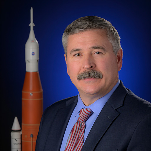
Mission Manager: Mike Sarafin
Mike Sarafin is the Artemis mission manager at NASA Headquarters in Washington. In this role, he leads the Mission Management Team for Artemis I, providing oversight and responsibility for critical decisions across all flight phases (launch, in-space, and recovery), with support from team members and advisors with technical expertise in various areas. Prior to flight he acts as a senior technical leader that integrates mission requirements, mission planning, operations and flight readiness leading to mission execution.

Launch Director: Charlie Blackwell-Thompson
Charlie Blackwell-Thompson is the Artemis I launch director at NASA’s Kennedy Space Center in Florida, overseeing the countdown and liftoff of SLS and Orion. Named to the position in January 2016, Blackwell-Thompson is NASA’s first female launch director. Her role includes leading and managing the launch operations planning and execution for the Exploration Ground Systems Program. She also serves as the cross-program lead to the Launch Integration team responsible for integration and coordination of launch operations across the three programs: SLS, Orion and EGS. In her role as launch director, she manages the development of all launch countdown plans, philosophy, and launch and scrub turnaround procedures and schedules, as well as training approaches.
Lead Flight Director: Rick LaBrode
Rick LaBrode is the Artemis I lead flight director at NASA’s Johnson Space Center in Houston. In this role, he is responsible for guiding the flight control team in Mission Control to execute the mission objectives of the Orion spacecraft. LaBrode coordinates with teams to plan the mission design and strategy, develops procedures and flight rules on how to operate the spacecraft, and is responsible for the overall success of the mission, beginning with the Space Launch System rocket firing from space to propel Orion toward the Moon, through its trek back to Earth. As a flight director, LaBrode is involved in critical decision-making when needed and oversees the flight controllers who use real-time telemetry to track and monitor technical and safety aspects during the mission.

Ascent and Entry Flight Director: Judd Frieling
Judd Frieling serves as the Artemis I ascent and entry flight director at Johnson. Frieling is responsible for two phases of flight: launch of the Orion spacecraft atop the Space Launch System (SLS) rocket as they clear the launch pad and climb toward the Moon, and Orion’s return from the lunar vicinity as it enters Earth’s atmosphere and splashes down in the ocean. From the Mission Control Center, Frieling oversees the flight control team – who have real-time command and control capability of the spacecraft – monitoring the launch performance of Orion and the SLS engines and its boosters, as well as the propulsions stages as the rocket clears the launch pad. During re-entry, the team tracks Orion as it speeds through Earth’s atmosphere and descends during a parachute-controlled splashdown of the crew module in the Pacific Ocean.

Recovery Director: Melissa Jones
Melissa Jones is the Artemis I landing and recovery director for the Exploration Ground Systems program at Kennedy. Jones is responsible for leading NASA’s efforts for nominal and contingency retrieval of flight crew and crew module hardware worldwide. In this position, she also will lead the Recovery Team that will partner with the U.S. Navy to recover the Orion crew module from the Pacific Ocean.
Program Management

NASA Orion Program Manager: Howard Hu
Howard Hu is manager of the Orion program at Johnson. As Orion program manager, he is responsible for oversight of design, development, production, and operations of the Orion spacecraft that will carry humans farther into space than ever before.

NASA Space Launch System Program Manager: John Honeycutt
John Honeycutt is manager of the SLS program at Marshall. He is responsible for directing SLS program activities leading to development of America’s deep-space rocket for human and scientific exploration.

NASA Exploration Ground Systems Program Manager: Mike Bolger
Mike Bolger is manager of the EGS program at Kennedy. He is responsible for leading the government and contractor team that is preparing the ground systems, infrastructure, facilities, and processes required to support NASA’s next-generation space launch systems and spacecraft.
Exploration Systems Development Mission Directorate Leadership

Associate Administrator: James Free
James Free is associate administrator of the Exploration Systems Development Mission Directorate at NASA Headquarters. As associate administrator, he provides leadership and management of human spaceflight systems development for programs critical to Artemis and NASA’s Moon and Mars exploration goals.

Deputy Associate Administrator: Cathy Koerner
Cathy Koerner is deputy associate administrator of the Exploration Systems Development Mission Directorate at NASA Headquarters. In this role, she is responsible for establishing and defining future space exploration architectures while overseeing development of new space transportation systems and supporting capabilities that are critical for human-led deep space exploration and scientific research.

Deputy Associate Administrator for Common Exploration Systems Development Division: Tom Whitmeyer
Tom Whitmeyer is the deputy associate administrator for the mission directorate’s Common Exploration Systems division. In his role, Whitmeyer provides executive leadership and program integration of SLS, Orion, and EGS programs, and the overall systems integration, program planning and control, and mission operations of the enterprise.
Lead Contractors & Suppliers
Men and women across America and in Europe are building the systems to support missions to the Moon, Mars, and beyond. These missions are critical to the space economy, fueling new industries and technologies, supporting job growth, and furthering the demand for a highly skilled workforce. Since its inception, every state in America has contributed to the success of Artemis, with companies hard at work on innovations that will help establish a long-duration human presence at the Moon.
Lead contractors for Orion, SLS, and EGS include:
- Lockheed Martin for Orion
- Aerojet Rocketdyne, Boeing, Northrop Grumman, and Teledyne Brown for the Space Launch System
- Jacobs for Exploration Ground Systems
These lead contractors currently have thousands of suppliers contributing to Orion, the SLS rocket, and the spaceport at Kennedy from all 50 states. With NASA investments, additional U.S. companies, including small businesses, are advancing technologies and systems needed for the Artemis program.
For more information and a map of Artemis partners, visit
https://www.nasa.gov/content/artemis-partners
European Space Agency
In addition, workers in the U.S. and 10 European countries provide work on Orion’s European Service Module. The European Service Module is ESA’s contribution to NASA’s Orion spacecraft. It provides electricity, water, oxygen and nitrogen as well as keeping the spacecraft at the right temperature and on course. European countries include Germany, Italy, Switzerland, France, Belgium, Sweden, Denmark, Norway, Spain, and The Netherlands. Airbus is the lead contractor under ESA for the service module. The final product is assembled in Europe before being shipped to Kennedy. International partnerships play a key role in achieving the agency’s goals, and establishing a safe, peaceful, and prosperous future in space.
https://www.esa.int/orion
Lockheed Martin
Lockheed Martin is the lead contractor for the design, development test and production of the Orion spacecraft. As lead contractor for Orion, Lockheed Martin designed and builds the spacecraft’s crew module – where astronauts will fly ̶ the launch abort system, and crew module adapter. It also integrates the European Service Module into a completed Orion spacecraft. Lockheed Martin performs the majority of the Orion engineering work in Denver, manufactures the crew module pressure vessel and thermal protection materials at the Michoud Assembly Facility in New Orleans, and completes final assembly of the spacecraft in Florida at the Kennedy Space Center and Spacecraft, Test, Assembly and Resource (STAR) Center.
https://www.lockheedmartin.com/en-us/products/orion.html
Aerojet Rocketdyne
Aerojet Rocketdyne is the lead contractor for the four RS-25 engines that will be used to propel SLS during its 8.5-minute climb to space and the RL10 engine that powers the rocket’s interim cryogenic propulsion stage. Additionally, Aerojet Rocketdyne provides eight auxiliary engines and 12 reaction control thrusters for the Orion crew module as well as the jettison motor for the launch abort system. The company also manufactures the high-pressure helium tanks that inflate Orion’s flotation system for water-based landings.
https://www.rocket.com/space/artemis
Boeing
Boeing is the lead contractor for the design, development, test, and production of the SLS core stage and ICPS, as well as development of the flight avionics suite. Boeing built and tested the core stage for the Artemis I mission. The SLS core stage is the world’s tallest rocket stage. It will store cryogenic liquid hydrogen, liquid oxygen, and all the systems that will feed the stage’s four RS-25 engines. It also houses the flight computers and other avionics needed to control the rocket’s flight. The ICPS provides in-space propulsion after the solid rocket boosters and core stage are jettisoned.
https://www.boeing.com/space/space-launch-system/launch/index.html
Northrop Grumman
Northrop Grumman is the lead contractor for the design, development, testing, and production of the twin solid rocket boosters that provide nearly 80 percent of initial thrust for SLS. Additionally, Northrop Grumman provides 16 booster separation motors, designed to push the spent solid rocket boosters away from the core stage, for each launch. Northrop Grumman also produces the launch abort motor and the attitude control motor for the Orion spacecraft’s launch abort system.
https://www.northropgrumman.com/space/nasas-artemis-program/
Teledyne Brown Engineering
Teledyne Brown Engineering is the lead contractor for the launch vehicle stage adapter, providing engineering, technical support, and hardware for the Artemis I adapter and structural test article. Teledyne Brown manufactures the adapter using the friction stir welding tools in the Advanced Weld Facility at Marshall.
https://www.tbe.com/what-we-do/markets/space
Jacobs
Jacobs is the lead contractor for NASA’s Exploration Ground Systems Program at Kennedy. In this role, the Jacobs team oversees launch operations and integrates Artemis spaceflight hardware at Kennedy. Working in multiple facilities across Kennedy, Jacobs receives all of the hardware and conducts final processing, assembly, testing and integration in preparation for launch. Jacobs has worked with NASA to develop the Artemis ground operations and launch control software, and will be on consoles in the Launch Control Center firing room supporting the countdown on launch day. The Jacobs team also supports the Orion recovery operations after splashdown.
https://www.jacobs.com/projects/artemis

Airbus
Orion’s European Service Module is built by Airbus under a contract with ESA. The service module will provide critical functions such as the propulsion system to get to the Moon, and astronaut life support systems such as water, oxygen, and nitrogen. Many companies all over Europe, as well as companies in the United States, supply components for the service module. The final product is assembled in Europe before being shipped to NASA. ESA has signed contracts with Airbus for the construction of a total of six European Service Modules.
https://www.airbus.com/space/space-infrastructures/Orion-ESM.html
Communications Contacts
Artemis
NASA Headquarters
Exploration Systems Development Mission Directorate
Public Affairs
Kathryn Hambleton
202-358-1409
kathryn.hambleton@nasa.gov
Exploration Systems Development
Mission Directorate Public Affairs
Rachel Kraft
202-365-7575
rachel.h.kraft@nasa.gov
Social Media
Thalia Patrinos
202-358-3887
thalia.k.patrinos@nasa.gov
NASA’s Kennedy Space Center
Artemis Public Affairs
Tiffany Fairley
321-867-7986
tiffany.l.fairley@nasa.gov
NASA’s Johnson Space Center
Artemis Public Affairs
Gary Jordan
281-483-5111
gary.j.jordan@nasa.gov
Astronaut Office Public Affairs Specialist
Megan Dean
281-483-5111
Megan.dean@nasa.gov
Orion
NASA’s Johnson Space Center
Orion Public Affairs
Laura Rochon
281-483-5111
laura.a.rochon@nasa.gov
NASA’s Langley Research Center
Orion – Launch Abort System Public Affairs
Kristyn Damadeo
757-864-1090
kristyn.damadeo@nasa.gov
NASA’s Glenn Research Center
Orion – European Service Module Public Affairs
James “Jimi” Russell
216-433-2894
james.j.russell@nasa.gov
Lockheed Martin
Communications
Gary Napier
720-224-7955
gary.p.napier@lmco.com
ESA – European Space Agency
Communication Programme Office for Human and Robotic Exploration
Rosita Suenson
+31 652 062 158
rosita.suenson@esa.int
Senior Editor
Julien Harrod
+31 617 02 51 84
julien.harrod@esa.int
Media Relations
Ninja Mennings
media@esa.int
Airbus
Media Relations
Ralph Heinrich
+49 171 304 9751
ralph.heinrich@airbus.com
Space Launch System
NASA’s Marshall Space Flight Center
Space Launch System Public Affairs
Tracy McMahan
256-682-5326
tracy.mcmahan@nasa.gov
Space Launch System Public Affairs
Ray Osorio
256-267-2909
ramon.j.osorio@nasa.gov
Space Launch System Public Affairs
Corinne Edmiston
256-975-6798
corinne.m.edmiston@nasa.gov
NASA’s Michoud Assembly Facility
Strategic Communications
Craig Betbeze
504-419-5333
craig.c.betbeze@nasa.gov
NASA’s Stennis Space Center
Office of Communications
Lacy Thompson
228-688-3050
calvin.l.thompson@nasa.gov
Aerojet Rocketdyne
SLS and Orion Media Relations
Mary Engola
571-289-1371
mary.engola@rocket.com
SLS Media Relations
Todd McConnell
561-302-8358
Todd.McConnell@Rocket.com
Boeing
Media Relations
Steve Siceloff
(281) 253-8089
steven.p.siceloff@boeing.com
Media Relations
Josh Barrett
321-607-4118
joshua.d.barrett2@boeing.com
Northrop Grumman
Propulsion Systems/SLS & Launch Abort
Kay Anderson
435-230-2787
kay.anderson@ngc.com
Propulsion Systems/SLS & Launch Abort
Scott Day
480-352-3798
scott.day@ngc.com
Propulsion Systems/SLS & Launch Abort
Kendra Kastelan
385-232-0297
kendra.kastelan@ngc.com
Teledyne Brown Engineering
Director of Marketing, Communication and Strategic Integration
Jessica Sanders
256-726-1385
jessica.sanders@teledyne.com
United Launch Alliance
Senior Manager, Strategic Communications
Julie Arnold
321-423-4594
Julie.a.arnold@ulalaunch.com
Exploration Ground Systems
ASA’s Kennedy Space Center
Space Launch System and Orion
Madison Tuttle
321-861-0493
madison.e.tuttle@nasa.gov
Vehicle Assembly Building/Launch Control
Center/Spanish language lead
Antonia Jaramillo Botero
321-501-8425
antonia.jaramillobotero@nasa.gov
Launch Pad 39B/ Mobile Launchers/Crawler-transporters
Tammy Long
321-427-3010
tammy.long@nasa.gov
Jacobs
Strategic Communications & Suppliers Lead
Katie Frakes
321-289-7863; 321-360-2781
katie.j.frakes@nasa.gov
Media Engagement Lead
Tracy Yates
321-750-1739
tracy.e.yates@nasa.gov
Media Relations
Paige Easley
601-248-7762
elizabeth.p.easley@nasa.gov
CubeSats
NASA’s Marshall Space Flight Center
Space Launch System
Tracy McMahan
256-682-5326
tracy.mcmahan@nasa.gov
Space Launch System
Corinne Edmiston
256-698-2638
corinne.m.edmiston@nasa.gov
Orion Payloads
Matroshka AstroRad Radiation Experiment (MARE)
German Aerospace Center (DLR)
MARE Project Manager
Dr. Thomas Berger
+49 2203 601 31 35
thomas.berger@dlr.de
Israel Space Agency (ISA)
Director of International Relations
Revital Karin Sela
RevitalS@most.gov.il
StemRad, LTD
CEO
Dr. Oren Milstein
USA: 813-808-3038
Israel: +972-54-255-1495
oren@stemrad.com
Callisto Technology Demonstration
Lockheed Martin
Communications
Gary Napier
303-971-4012; 720-224-7955
gary.p.napier@lmco.com
Manikin “Commander Moonikin Campos”
NASA’s Johnson Space Center
Orion Public Affairs
Laura Rochon
281-483-5111
laura.a.rochon@nasa.gov
Bio-Experiment-1
NASA’s Kennedy Space Center
Public Affairs
Mary MacLaughlin
321-867-3155
mary.maclaughlin@nasa.gov
Other
U.S. Navy
Public Affairs Officer, Expeditionary Strike Group 3
LCDR Lauren Spaziano
619-767-6833; 619-886-4293
lauren.spaziano@navy.mil
Additional Multimedia Materials
Media Resources
Social Media Links
NASA![]() https://www.twitter.com/NASA
https://www.twitter.com/NASA![]() http://www.facebook.com/NASA
http://www.facebook.com/NASA![]() http://www.instagram.com/NASA
http://www.instagram.com/NASA![]() https://www.youtube.com/NASA
https://www.youtube.com/NASA https://nasa.tumblr.com/
Artemis![]() https://twitter.com/NASAArtemis
https://twitter.com/NASAArtemis![]() https://www.facebook.com/NASAArtemis/
https://www.facebook.com/NASAArtemis/![]() https://instagram.com/nasaartemis
https://instagram.com/nasaartemis
Orion![]() http://twitter.com/NASA_Orion
http://twitter.com/NASA_Orion![]() https://www.facebook.com/NASAOrion
https://www.facebook.com/NASAOrion![]() http://www.flickr.com/photos/nasaorion https://nasaorion.tumblr.com/
http://www.flickr.com/photos/nasaorion https://nasaorion.tumblr.com/
Lockheed Martin![]() https://www.twitter.com/lmspace
https://www.twitter.com/lmspace![]() https://www.facebook.com/lockheedmartin
https://www.facebook.com/lockheedmartin![]() https://www.instagram.com/lockheedmartin
https://www.instagram.com/lockheedmartin![]() http://www.youtube.com/user/LockheedMartinVideos
http://www.youtube.com/user/LockheedMartinVideos
European Space Agency![]() https://www.twitter.com/esa
https://www.twitter.com/esa![]() https://www.facebook.com/EuropeanSpaceAgency
https://www.facebook.com/EuropeanSpaceAgency![]() https://instagram.com/europeanspaceagency/
https://instagram.com/europeanspaceagency/![]() https://www.youtube.com/user/ESA
https://www.youtube.com/user/ESA
Airbus![]() https://www.twitter.com/AirbusSpace
https://www.twitter.com/AirbusSpace![]() https://www.facebook.com/AirbusSpace/
https://www.facebook.com/AirbusSpace/![]() https://www.instagram.com/airbus_space
https://www.instagram.com/airbus_space![]() https://www.youtube.com/user/airbusds
https://www.youtube.com/user/airbusds
Space Launch System![]() https://twitter.com/NASA_SLS
https://twitter.com/NASA_SLS![]() https://www.facebook.com/NASASLS/
https://www.facebook.com/NASASLS/![]() https://flic.kr/s/aHsjw4fs4a
https://flic.kr/s/aHsjw4fs4a
Aerojet Rocketdyne![]() https://www.facebook.com/AerojetRdyne
https://www.facebook.com/AerojetRdyne![]() https://www.instagram.com/aerojet_rocketdyne
https://www.instagram.com/aerojet_rocketdyne![]() https://www.youtube.com/user/AerojetRocketdyne
https://www.youtube.com/user/AerojetRocketdyne
Boeing![]() https://www.twitter.com/BoeingSpace
https://www.twitter.com/BoeingSpace![]() https://www.facebook.com/Boeing/
https://www.facebook.com/Boeing/![]() https://www.instagram.com/boeing
https://www.instagram.com/boeing![]() https://www.youtube.com/user/boeing
https://www.youtube.com/user/boeing
Northrop Grumman![]() https://www.twitter.com/northropgrumman
https://www.twitter.com/northropgrumman![]() https://www.facebook.com/NorthropGrumman
https://www.facebook.com/NorthropGrumman![]() https://www.instagram.com/NorthropGrumman
https://www.instagram.com/NorthropGrumman![]() https://www.youtube.com/user/northropgrummanmedia
https://www.youtube.com/user/northropgrummanmedia
Exploration Ground Systems![]() https://twitter.com/NASAGroundSys
https://twitter.com/NASAGroundSys![]() https://www.facebook.com/NASAGroundSystems/
https://www.facebook.com/NASAGroundSystems/![]() https://flic.kr/s/aHsk6rHRz3
https://flic.kr/s/aHsk6rHRz3
Jacobs![]() https://twitter.com/JacobsConnects
https://twitter.com/JacobsConnects![]() https://www.facebook.com/JacobsConnects
https://www.facebook.com/JacobsConnects https://www.linkedin.com/company/jacobs/
![]() https://www.youtube.com/user/jacobsworldwide
https://www.youtube.com/user/jacobsworldwide![]() https://www.instagram.com/jacobsconnects/
https://www.instagram.com/jacobsconnects/
Kennedy Space Center![]() https://twitter.com/NASAKennedy
https://twitter.com/NASAKennedy![]() https://www.facebook.com/NASAKennedy/
https://www.facebook.com/NASAKennedy/![]() https://www.instagram.com/nasakennedy/
https://www.instagram.com/nasakennedy/![]() https://www.flickr.com/photos/nasakennedy/
https://www.flickr.com/photos/nasakennedy/![]() https://www.youtube.com/user/NASAKennedy
https://www.youtube.com/user/NASAKennedy
Johnson Space Center![]() https://twitter.com/NASA_Johnson
https://twitter.com/NASA_Johnson![]() https://www.facebook.com/NASAJSC
https://www.facebook.com/NASAJSC![]() https://www.instagram.com/nasajohnson/
https://www.instagram.com/nasajohnson/![]() https://www.flickr.com/photos/nasa2explore/
https://www.flickr.com/photos/nasa2explore/![]() https://www.youtube.com/user/ReelNASA
https://www.youtube.com/user/ReelNASA
Marshall Space Flight Center![]() https://www.twitter.com/NASA_Marshall
https://www.twitter.com/NASA_Marshall![]() https://www.facebook.com/nasamarshallcenter
https://www.facebook.com/nasamarshallcenter![]() https://www.instagram.com/nasa_marshall
https://www.instagram.com/nasa_marshall![]() https://www.flickr.com/photos/nasamarshall
https://www.flickr.com/photos/nasamarshall![]() https://www.youtube.com/user/NASAMarshallTV
https://www.youtube.com/user/NASAMarshallTV