


The 9×15 Low-Speed Wind Tunnel (9×15) is the most used low-speed propulsion acoustic facility in the world. It is the only national facility that can simulate takeoff, approach, and landing in a continuous subsonic environment.
Facility Overview
The 9×15 is a significant asset to the nation and the aero-propulsion community because of its unique ability to test large-scale hardware in a continuous subsonic air stream. With the ever-increasing demand for reducing aircraft noise, the importance of the 9×15 is greater than ever. Offering state-of-the-art acoustic capabilities, the facility is a vital part of the nation’s aeronautics research plans. Programs supported in this facility include a variety of commercial aircraft propulsion systems: the High-Speed Civil Transport, Advanced Tactical Fighter (ATF), Joint Strike Fighter (JSF) and other military short takeoff and vertical landing aircraft applications.
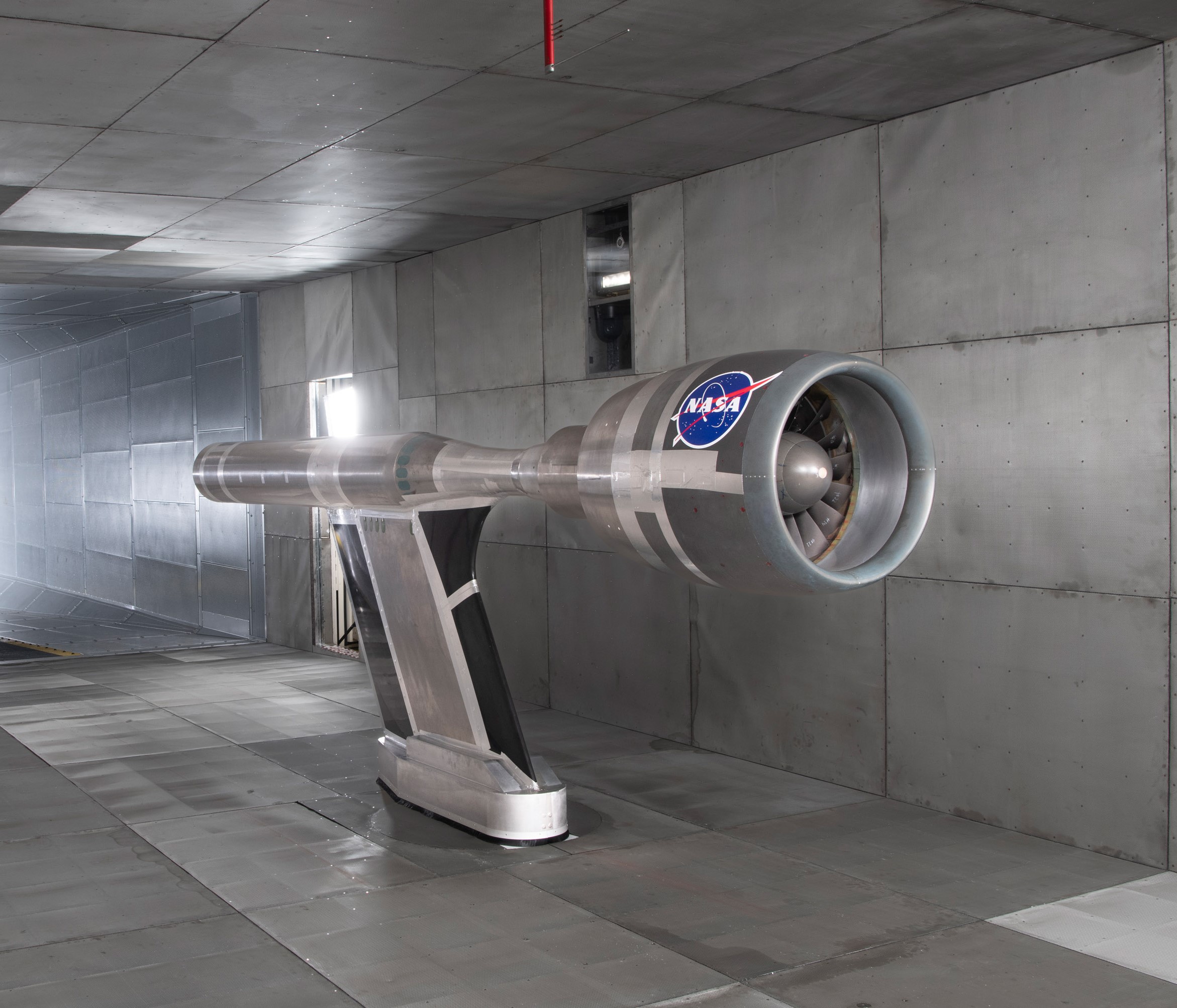
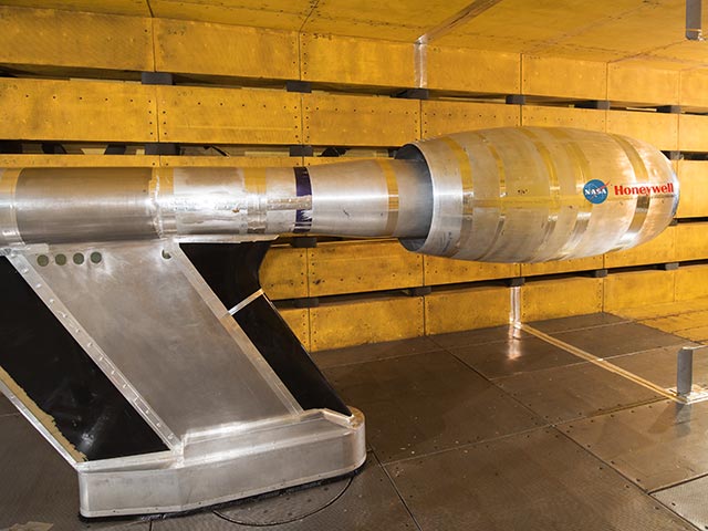
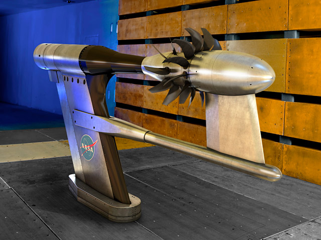
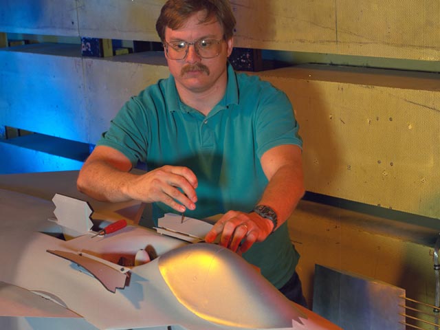
Built in 1968, this facility has unique and nationally recognized capabilities to evaluate aerodynamic performance and acoustic characteristics of nozzles, inlets and propellers.
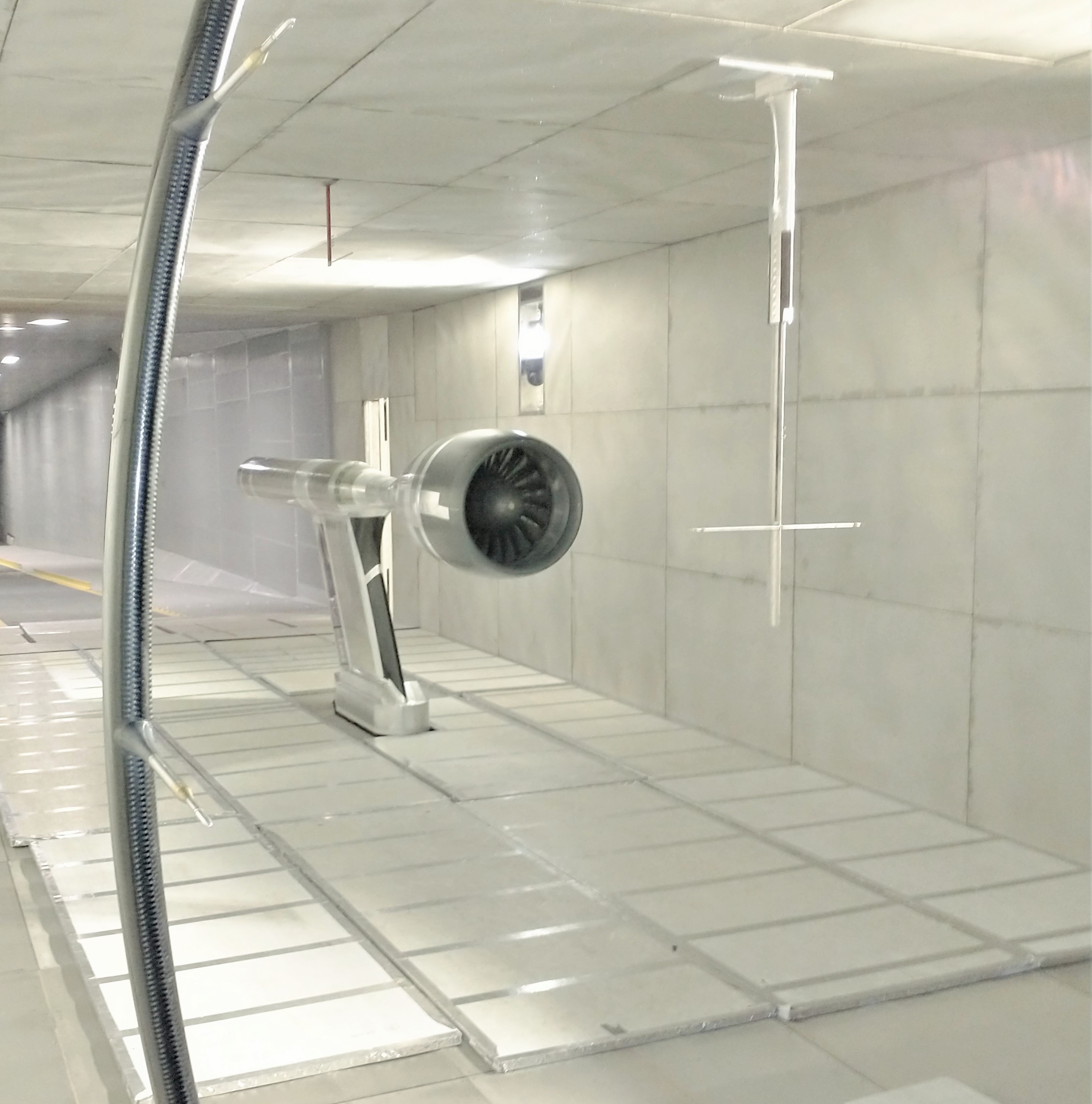
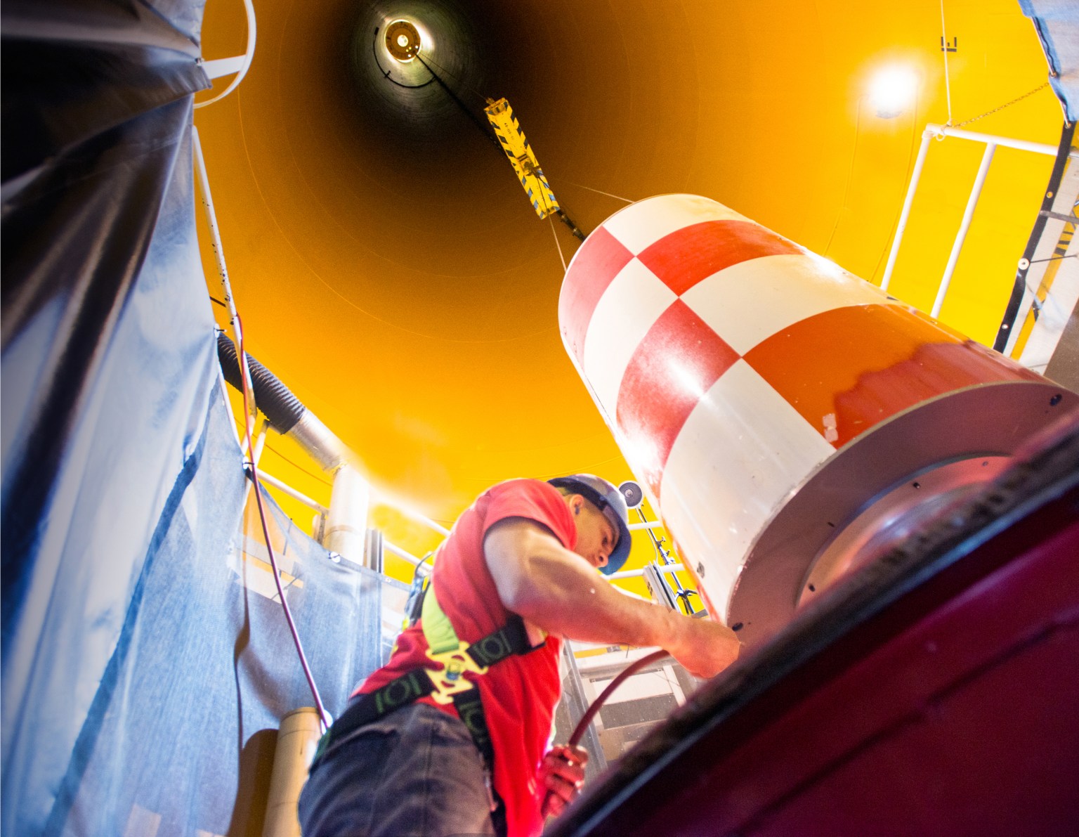
The facility is acoustically treated and equipped with microphones linked to a dynamic data system. A series of drive rig systems are available to power engine fan models for performance and acoustic testing. A unique “rotor alone nacelle” test capability allows isolation of “fan alone noise” by elimination of outlet guide vanes.
Specialized support systems include:
- Advanced optical imagery (sheet lasers, pressure-sensitive paint (PSP), and temperature-sensitive paint (TSP))
- High-pressure air
- Altitude exhaust
- 1,000- and 5,000-hp fan drive rig systems
- 750-hp (per shaft) counter-rotating drive rig system
- Rotor alone nacelle system
- Variety of available research test hardware
Quick Facts
The 9×15, housed in the return leg of the 8×6 Supersonic Wind Tunnel, provides a unique facility for testing large-scale hardware in a continuous subsonic air stream. The test section is 9 feet high by 15 feet wide by 33 feet long and provides airspeeds from 0 to 165 mph.
Take a virtual tour of our 9×15 Low-Speed Wind Tunnel.
| Airspeed | 0 to 165 mph |
| Test Section | 9 feet high by 15 feet wide by 33 feet long |
| Reynolds Number | 0 to 1.4×10⁶/ft |
| Dynamic Pressure | 0 to 72 psf |
| Temperature | Ambient to 550°R |
The 9×15:
- Is the most used low-speed propulsion acoustic facility in the world.
- Is the only national facility that can simulate takeoff, approach, and landing in a continuous subsonic flow wind tunnel environment.
- Maintains a series of drive rig systems to power engine fan models for performance and acoustic testing.
- Has supported Ultra-Efficient Engine Technology (UEET), Quiet Aircraft Technology (QAT), Versatile Affordable Advanced Turbine Engine (VAATE), the JSF, and the ATF.
Capabilities
The 9×15 provides customers with a facility capable of testing large scale aero-propulsion hardware.
Characteristics and Performance
- Test section size: 9 feet high by 15 feet wide by 33 feet long
- Mach number range: 0 to 0.21 (0 to 165 mph)
- Relative altitude: sea level
- Reynolds number: 0 to 1.4×10⁶/ft
- Dynamic pressure: 0 to 72 psf
- Stagnation pressure: atmospheric
- Temperature: ambient to 550°R
- Acoustic frequency cutoff: <630 Hz
Tunnel Support Systems
- Air: 40, 150, and 450 psig
- Service air: 125 psig
- Combustion air heater: 38 pps at up to 530 °F
- Exhaust: 16-in. line at 20 and 26 in. of Hg
- High-pressure air (2600 psig) storage: 981,000 scf
- Model cooling: available
- Model hydraulics: 15 gal/min at 2,900 psig max.
- Fan drive rigs: 1,000 and 5,000-hp single-shaft systems and 750-hp (per shaft) counter-rotating system
Model Support Systems
- Rotor alone nacelle system: side-wall-mounted test capability to enable isolation of fan alone noise by elimination of outlet guide vanes
- Turntables: floor-mounted model support systems with high-pressure and exhaust capability
Model Data and Control System Capabilities
- Pressure Systems
The 9×15’s electronically scanned pressure system consists of numerous 32 or 64 port miniaturized pressure scanner modules. Multiple measurement ranges are available to accommodate various needs. These can be located outside of the test chamber or within the test article. Each module has a check pressure to ensure correct performance. In-situ calibration performed via high accuracy standards. - Steady-State Data System
NASA Glenn uses Collect Observe Broadcast Record and Analyze (COBRA) for its standardized low-speed (under 1,000 samples per second per channel) data system. The system uses commercial-off-the-shelf (COTS) hardware and operating systems coupled with specialized data acquisition and application hardware and software modules. It has a flexible and scalable design that utilizes a distributed network architecture approach. This design allows the attachment of measurement devices from a wide range of vendors. This approach allows the system to evolve over time, permits the latest technology to be used that meets Glenn’s measurement requirements, and provides the environment for the best measurement methods to be applied.- Universal data server
- Runs the data processing engine (DPE), which collects, aggregates and records the data
- Performs engineering unit conversions and complex equations
- Distributes data to clients in near real time while acquisition and recording continue
- Data displays
- Run the DataViewer software
- Receive data from the COBRA network via the UDS
- Allow the user to view real-time data in numerical and graphical representations
- Synchronized time generator
- Provides Network Time Protocol (NTP), Precision Time Protocol (PTP) and inter-range instrumentation group (IRIG) signals to the data acquisition systems and nodes in the COBRA system
- Synchronized to the Global Positioning System (GPS) and United States Naval Observatory (USNO) via Glenn’s central time source
- Reprocessing data export server
- Allows the user to reprocess data (correct calculation, add calculations, change coefficients, etc.)
- Exports data to files
- Acquisition devices
- Modular and scalable with support for a wide variety of measurement devices:
- Analog input system
- Electromechanical scanning pressure
- Digital temperature scanners
- Frequency inputs
- Digital inputs/outputs (I/O)
- Avionics interfaces
- Modular and scalable with support for a wide variety of measurement devices:
- Universal data server
Please contact the facility manager for information on facility measurement systems.
- Dynamic Data System
The dynamic data system provides multichannel high-speed digitized acquisition of rapidly changing cyclic or nonperiodic impulse type events. The system consists of:- Programmable filter/amplifying front end
- 24-bit ∑Δ analog-to-digital (ADC) with anti-aliasing filter
- Counter channels and math channels are available
- Data transfer in near real time available upon request
- Custom displays
- Various sampling rater for differing bandwidth needs
- Flow Visualization
- PSP
- Sheet laser
- Oil flow visualization
- High-speed video
- Test Article Controls
- Digital model control system with graphical interface
- Automated test article sequencing system
Contact
9×15 Low-Speed Wind Tunnel (9×15)
Facility Manager: Michelle Lasic
216-433-3996
Michelle.Lasic@nasa.gov
Test Facility Management Branch
Acting Chief: Taylor Varouh
216-433-6347
Taylor.Varouh@nasa.gov
Using Our Facilities
NASA’s Glenn Research Center in Cleveland provides ground test facilities to industry, government, and academia. If you are considering testing in one of our facilities or would like further information about a specific facility or capability, please let us know.
Gallery


/Hubble%20Space%20Telescope%20(A).png)