


![Request for Information – Potential [Placeholder for Prize]](https://assets.science.nasa.gov/dynamicimage/assets/science/psd/solar/2023/09/s/solarsystem_0.jpg?w=1024)


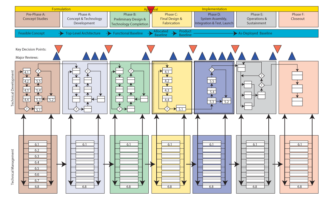
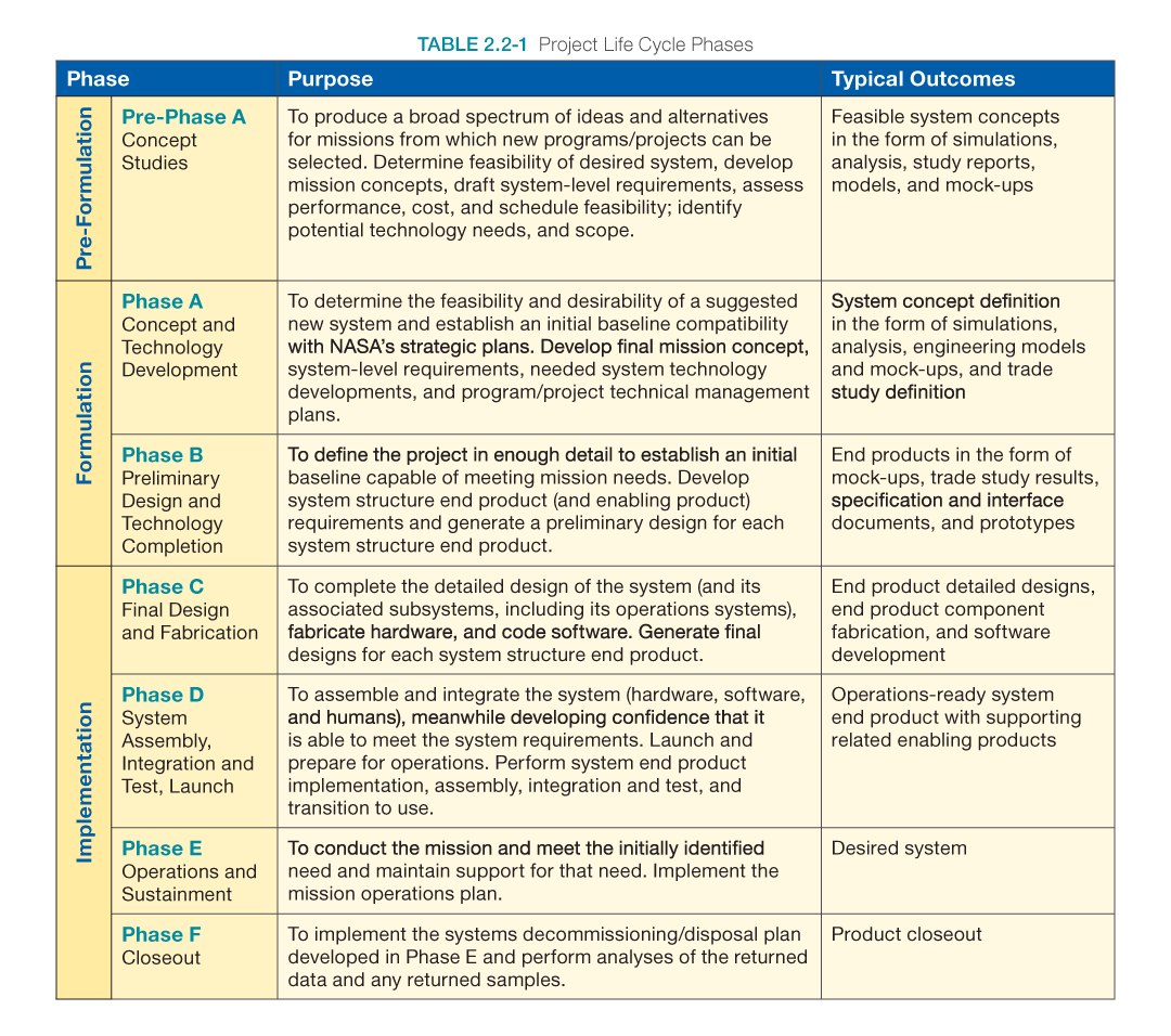
Figure 2.2-1 conceptually illustrates how the SE engine is used during each phase of a project (Pre-Phase A through Phase F). The life cycle phases are described in Table 2.2-1. Figure 2.2-1 is a conceptual diagram. For full details, refer to the poster version of this figure, which is located at https://nen.nasa.gov/web/se/doc-repository.
The uppermost horizontal portion of this chart is used as a reference to project system maturity, as the project progresses from a feasible concept to an as-deployed system; phase activities; Key Decision Points (KDPs); and major project reviews. The next major horizontal band shows the technical development processes (steps 1 through 9) in each project phase. The SE engine cycles five times from Pre-Phase A through Phase D. Note that NASA’s management has structured Phases C and D to “split” the technical development processes in half in Phases C and D to ensure closer management control. The engine is bound by a dashed line in Phases C and D. Once a project enters into its operational state (Phase E) and closes out (Phase F), the technical work shifts to activities commensurate with these last two project phases. The next major horizontal band shows the eight technical management processes (steps 10 through 17) in each project phase. The SE engine cycles the technical management processes seven times from Pre-Phase A through Phase F.