


10.0 CREW INTERFACES
This section covers the crew interfaces through which static and dynamic information is exchanged between the crew and the system (primarily through controls and displays). Well-designed crew interfaces are critical for crew safety, optimal human performance, and minimize training.
Displays may be visual, audible, or haptic. Visual displays deliver information by using visible media to present text, graphics, colors, indicator lights, images, video, animations, and symbols. This information can be provided on dynamic displays such as Graphic User Interface (GUIs) or control panels or with static displays, such as labels and placards. Audio displays deliver information using sound and include voice communication and audible alerts. Haptic displays deliver information using the sense of touch by applying forces, vibrations, or motions for the purpose of information presentation.
10.1 Standardization & Consistency
Crew interfaces that are consistent require less crew training, and generally result in fewer operational errors and lower cognitive workload. The most efficient way to promote consistency is through the use of standards.
10.1.1 Crew Interface Consistency
[V2 10005] The system shall provide crew interfaces that are consistent in appearance, arrangement, location, and operation throughout systems.
[Rationale: Consistency refers to the level of similarity in visual style and operation with and among different crew interface designs that provide similar functions. This includes displays, controls, and procedures. Systems that have been designed with consistency in mind require less training and feel familiar. The number of different codes and ways of operating are minimized, which reduces crew training, cognitive workload, and operational errors. The use of lower-level design requirements and guidelines that specify the “look” (visual characteristics) and “feel” (style of interaction or operation) can help promote consistency.]
10.1.2 Operations Nomenclature Standardization
[V2 10006] Operational nomenclature shall be standardized throughout a system.
[Rationale: It is imperative that spaceflight operations personnel, including all ground personnel and crewmembers, communicate using common nomenclature that unambiguously and uniquely defines all aspects of crew operations. This includes, but is not limited to, defining the operations, the methods employed by the crew, the equipment, hardware and software items used, and any associated data. This nomenclature is also to be common among all operational products, including inventory, commands, procedures, displays, planning products, reference information, system handbooks, system briefs, mission rules, schematics, and payloads operations products.]
10.1.3 Display Standards
[V2 10150] The system shall meet the Display Standard in Appendix F.
[Rationale: A program-wide display standards document and icon library are to specify and archive characteristics of the display design, including text, graphics, and icons. These products result in cost savings due to less crew training and rework and increased safety due to reduced errors with a familiar design and simplified label verification. The display standard is applicable to GUIs and physical hardware displays and indicator lights, such as those found on non-GUI alert, equipment, and control panels. It is not applicable to static displays of information such as labels and placards.]
10.1.4 Labeling Plan and Icon Library
[V2 10151] The system shall provide labels that are consistent with a Labeling Plan and Icon Library as established by the program.
[Rationale: A program-wide labeling plan and icon library are to specify and document characteristics of the labels and icons used in human interfaces. These characteristics include location, orientation, material, font, size, style, color, etc., and includes visual examples and vehicle placement. Program-wide documents result in cost savings due to reduced redundancy in development and less crew training. The use of consistent labels and icons promotes increased safety and efficiency due to reduced errors with a consistent design.]
10.2 Information Design & Data Management
10.2.1 Stale, Missing, or Unavailable Data
[V2 10020] The system shall provide visual indication when a data parameter is stale, missing, unavailable, or unknown.
[Rationale: The human operator must be made aware/cued when display systems are no longer receiving live telemetry, and data values may be “stale” or missing. The indicator can be the same for stale, missing, or unavailable data or unique indications for each type of data (stale, missing, unavailable, or unknown). Use of standard color and/or symbology to represent missing data prevents misinterpretation and errors regarding the system’s state.]
10.2.2 Maximum System Response Times
[V2 10022] The system shall provide positive indication of crew-initiated control within the times specified in Table 10.2-1—Maximum System Response Time(s).
[Rationale: A positive indication of control activation is used to acknowledge the system response to the control action. For example, a physical detent, an audible click, an integral light, or a switch position may be used to provide a positive indication of control activation. Timely feedback to inputs is critical for crew to feel they are interacting with a responsive system. Slow response times can result in redundant inputs to the system, which can add to crew confusion and errors. A response time of 0.1 s gives the feeling of instantaneous response, and a response time of 1.0 s keeps the user’s flow of thought seamless (Miller, 1968; Card, et al., 1991; Nielsen, 1993, 2010). This technical requirement does not apply to manual piloting tasks.]
Table 10.2-1—Maximum System Response Time(s)

10.2.3 System Latency for Piloting
[V2 10152] The system shall provide a display system latency for information elements used in vehicle manual flight control tasks and the monitoring of time critical automated flight control tasks, including translation and rotation, that does not exceed a delay of 50ms.
[Rationale: Information elements used in vehicle piloting tasks, including translation and rotation, are to allow for satisfactory levels of performance as measured by handling qualities ([V2 10004] Handling Qualities – Level 1 and [V2 5052] Handling Qualities – Level 2]) and workload assessments ([V2 5007] Cognitive Workload and [V2 10200] Physical Workload). Display system latency is the time delay between the change in vehicle dynamics and the representation of associated new information on the display (total time from sensors to data presentation on the display). This is required to ensure piloting display elements that translate or rotate will do so smoothly without distracting or objectionable jitter, jerkiness, or ratcheting effects. Any lag introduced by the display system needs to be consistent with the vehicle control task demands associated with that parameter (e.g., based upon the gain level of the task, and the importance of the parameter of interest in the task).]
10.2.4 Command Confirmation
[V2 10080] The system shall require operator confirmation before completing critical, hazardous, irreversible, or destructive commands.
[Rationale: Critical, hazardous, irreversible, or destructive commands are to be prevented from being accidentally issued, which can be accomplished by requesting confirmation from the crew, thus reducing the chance of errors.]
10.2.5 Mode Change Command
[V2 10153] The system shall require an explicit command to change between simulation, test, or operational mode.
[Rationale: An explicit action to move between modes raises situation awareness and decreases accidental activation of an unintended mode.]
10.2.6 Critical Information Design
[V2 10113] The system shall provide data critical to mission planning, mission operations, system maintenance, and system health and status at an appropriate level of detail in a form that does not require mental transposition or computation, memory, or repetitive navigation.
[Rationale: The system is to provide all types of data needed by the crew to perform their tasks at the proper level of detail needed for each task in such a way that it is rapidly recognized and understood. Information displays include electronic and non-electronic media (e.g., fixed or mobile electronic displays, labels, procedures, placards). Data may be presented on different displays, including mobile devices that are an extension of other display devices or an independent device. Task analysis can help define data and level of detail needed for crew task performance.]
10.2.7 Data Update Rates
[V2 10123] The system shall operate at a rate that enables the crew to perform tasks effectively and efficiently, e.g., within acceptable error limits and scheduled operating times.
[Rationale: Response times that are too long prevent the crew from performing tasks effectively and efficiently; thus, minimal system response times are to be established for information management functions.]
10.2.8 Data Availability
[V2 10124] The system shall provide the crew with data to perform tasks at each workstation where those tasks are to be performed.
[Rationale: Design requirements are to specify which tasks are to be performed at which workstations and subsequently ensure that all task-relevant data be available at those workstations. This includes the capability for the operator to transport information from a fixed display to another location where there is no permanent display device. This can be accomplished via portable display or printed material. Task and data needs are identified by task analysis.]
10.2.9 Information Management Methods and Tools
[V2 10120] The information management system shall provide methods and tools that allow the crew to effectively input, store, receive, display, process, distribute, update, and dispose of mission data.
[Rationale: The system is to provide the hardware and software architecture, including crew interfaces necessary, to manage all of the data in the information management system. Usability testing can help ensure that the information management methods and tools provided are easy to use and effective.]
10.2.10 Information Management Security
[V2 10125] The system shall have features for the protection of sensitive and private data, transmission, secure viewing, and sender verification.
[Rationale: Data sensitivity and protection or handling measures are to be identified such that mechanisms for the protection of the data such as encryption or password protection can be put in place.]
10.2.11 Information Management Ground Access
[V2 10126] The system shall allow for ground access to perform all onboard database functions without crew intervention.
[Rationale: Ground personnel are to have the capability to access and perform data management functions for all onboard data. Architecture is to be in place to support this as a ground-to-vehicle interaction, without crew participation. This access is to take the following into consideration: data protection, data transmission bandwidth, and—most importantly— visibility to the crew. Although the crew is not required to accomplish these ground-initiated functions, the crew is to be aware that the operations will occur, are presently occurring, or have taken place. Consideration for ground access during real-time crew operations may need to be limited as communication time increases.]
10.2.12 Information Backup and Restoration
[V2 10129] The system shall provide for 1) automatic backup and crew restoration of information essential for system functionality, and 2) crew-initiated backup and restoration of information that can be generated or changed by crew during the mission.
[Rationale: Measures such as data backups and data restores are to be in place to ensure that data are protected from accidental loss. Backups are to occur automatically for critical data that cannot be recreated; backups for less critical data are to be initiated on crew request, using standard user interface commands.]
10.2.13 Alternative Information Sources
[V2 10130] The system shall provide alternative information sources for use in the event of the loss of the information management system.
[Rationale: In the event that the information management system becomes unavailable, the system needs to ensure that backup information sources are available for critical tasks, e.g., emergency procedures may have paper cue cards.]
10.2.14 Software System Recovery
[V2 10131] The system shall be rapidly recoverable from a software system crash.
[Rationale: In the event of a system failure, the information management software is to be sophisticated enough to be rapidly recovered. The minimum time delay that is acceptable before the information management system becomes operational after a system crash is to be identified by the program.]
10.3 Alerts
10.3.1 Distinguishable and Consistent Alerts
[V2 10114] The system shall provide distinct visual and audio annunciations to the human operators for emergency, warning, and caution events which require human operator action, and advisory alerts that are necessary for human operator situation awareness as specified in Table 10.3-1—Table Alert Type and Annunciation Table.
[Rationale: Visual and audio annunciations are to be defined and provided for all levels of alerts. Annunciations for emergency, warning and caution alerts are to have dual coding, e.g., be seen and heard, and are to be distinctive and identifiable. Advisory alerts may or may not have audio tones associated with this class of alert. Audio annunciations can incorporate speech alarms as a way to provide information efficiently and effectively promote quick and accurate responses from human operators.]
10.3.2 Alert Prioritization
[V2 10175] The System shall prioritize alerts per Table 10.3-1—Table Alert Type and Annunciation Table.
[Rationale: Prioritization of auditory and visual alerts is required to avoid different simultaneous alerts, so that crew’s attention is focused on the most critical alert. If multiple alerts trigger simultaneously, the system continuously annunciates the highest priority alert until it is acknowledged by the crew. Strategies will need to be developed to manage multiple alerts within a priority. Examples of such strategies include 1) a speech alert that states multiple alerts are in effect, or 2) establishment of sub-priorities within a priority level (e.g., some warnings may be more severe than other warnings, and prioritized for annunciation).]
10.3.3 Reduced Initial Alert Annunciation Level
[V2 10176] The System shall provide a “pre-alert” for auditory annunciations whereby the same alarm is annunciated 10dB lower than its final calibrated level.
[Rationale: The pre-alert is intended to prevent a “startle effect” through a reduced initial onset as shown in Figure 10.3.1-1—Example Alert Waveform. The first iteration of the alarm is 10 decibels (-10 dB) below the full alarm level. Successive iterations are at the full alarm level.]
Table 10.3-1—Alert Type and Annunciation Table
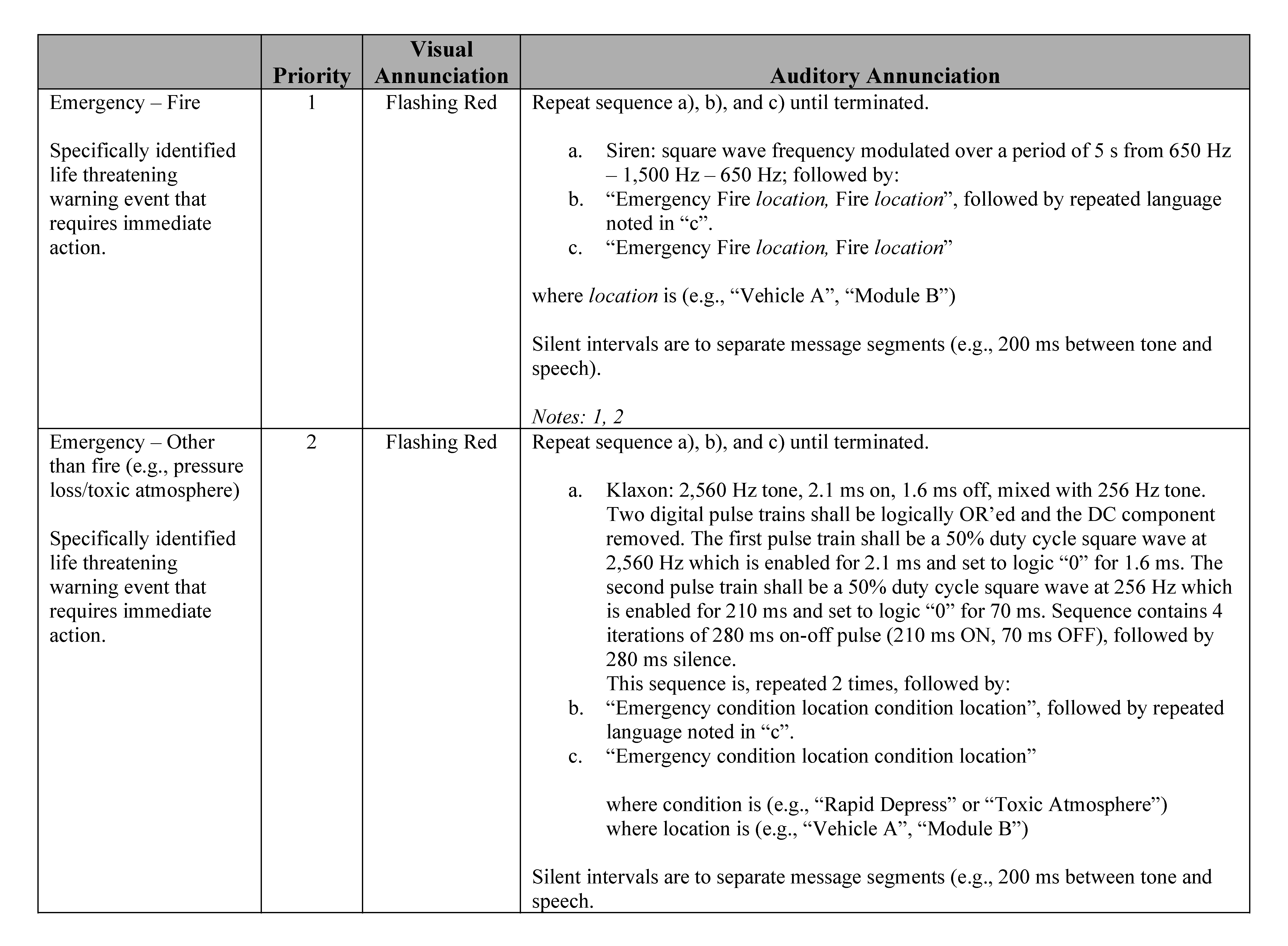
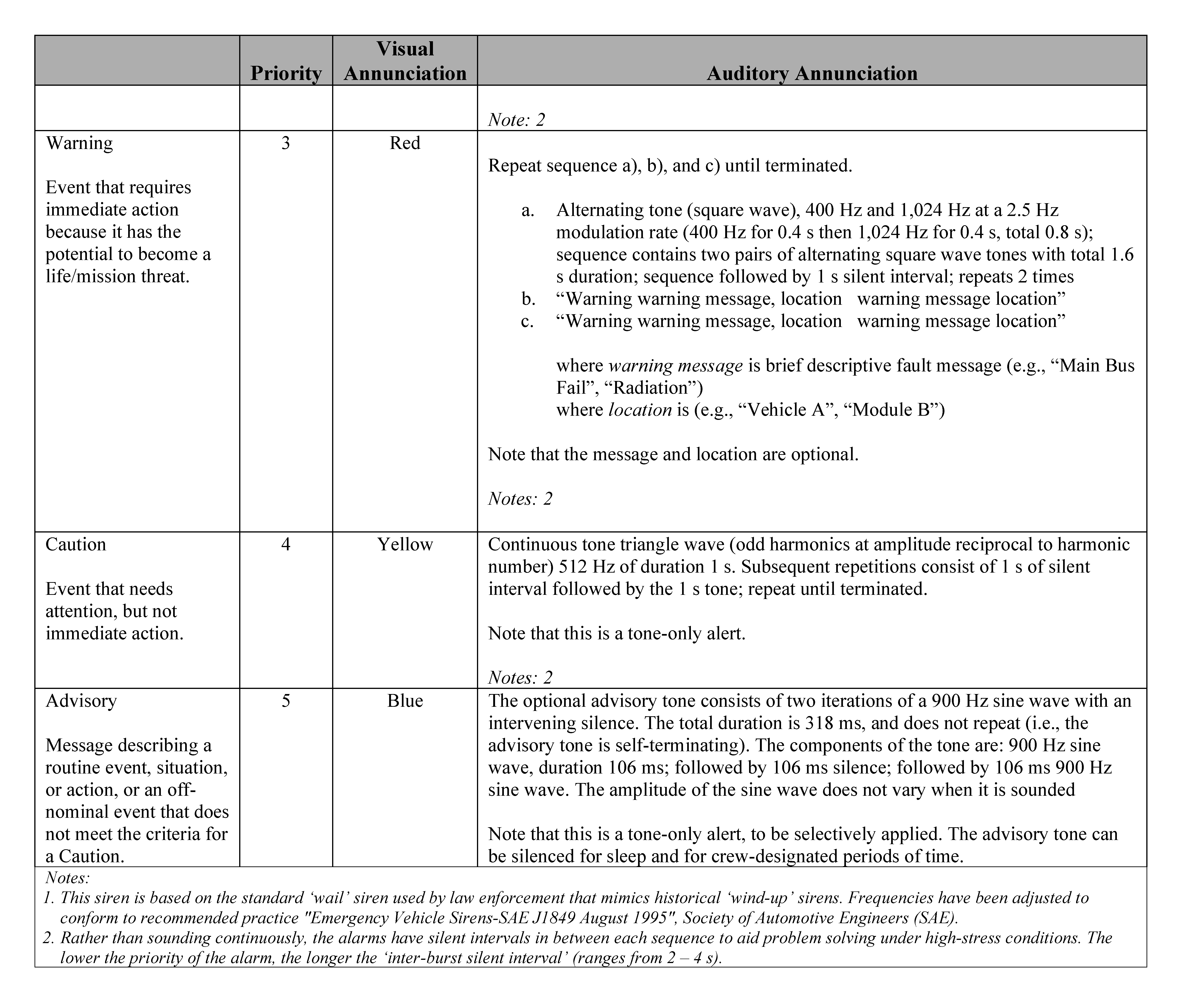
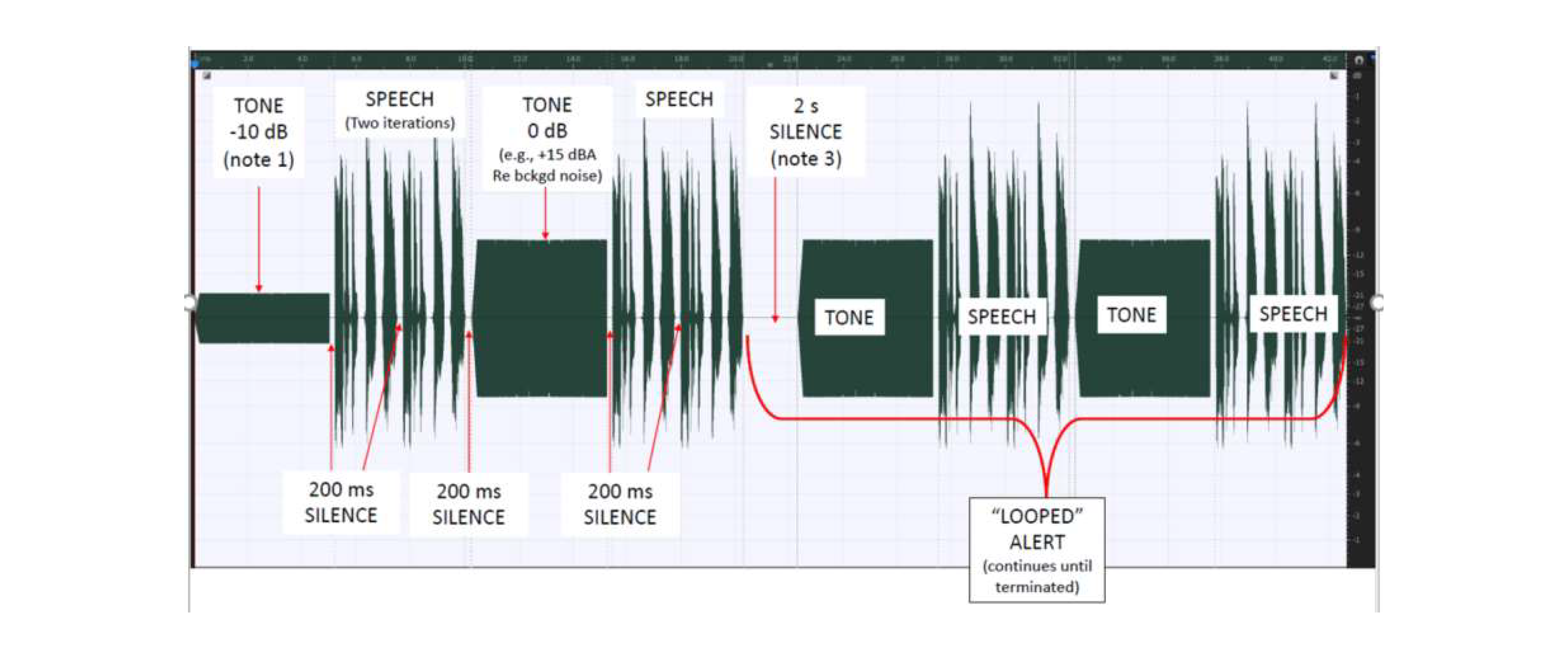
Figure 10.3-1—Example Alert Waveform
Figure 10.3.1-1—Example Alert Waveform diagram shows basic structure of alerts. The first iteration of the alarm is 10 decibels (-10 dB) below the full alarm level. Successive iterations are at the full alarm level. The buffer plays initially from time 0 to time t2; and then repeats from the loop start point until terminated.
10.3.4 Parameter Notifications
[V2 10115] The system shall notify the human operators if the selected system parameters are outside of tolerance.
[Rationale: A parameter is a defined value that an automatic control system is designed to maintain and include but are not limited to: high and low absolute set-points, deviation, rate of change, command disagreement, calculated, bit-pattern bit-mapped, controller output, system diagnostic, instrument diagnostic, bad measurement, statistical process control, common (group), or others. Human operators may be able to select parameters in an automatic control system. If a parameter is attempted to be changed to one that is outside of system tolerance, the system will provide consequence analysis and consequence guidance to the human operator that a change has been attempted that puts parameters outside of a tolerance or safe setting. The consequence alert acts as a check to verify that the human operator intentionally selected that change and informs them that there is a consequential impact or hazard associated with a parameter set to this range.]
10.3.5 Alert Signal Enable
[V2 10154] The system shall allow alert functions to be enabled by human operator.
[Rationale: Alert functions may be inhibited, shelved, or suppressed when required; when the reason for the inhibition, shelving, or suppression is no longer valid, the human operators must have a means to enable the alert function.]
10.3.6 Alert Signal Inhibit
[V2 10155] The system shall allow the human operator to inhibit alert functions that are Out-ofService (OoSVC).
[Rationale: An inhibited alert function is no longer monitored for system changes and, as a result, will not be visually or audibly annunciated or logged as an event (e.g., repeated false alarms due to a sensor issue). Long-term alert inhibition is placing the alert function in an outof-service state with the intention of not enabling the alert function in the near future. Alert inhibition is a long-term strategy for preventing nuisance alerts when equipment or systems are off-line for an extended period, or the alert function is no longer required or relevant. All alert functions must be enabled unless they are inhibited (shelved or out-of-service (OoSVC)) in accordance with a defined, implemented, and controlled inhibition methodology. The main difference between shelving and inhibiting an alert function is that a shelved (temporary) alert function will automatically return to service after the expiration of the shelving period and an inhibited alert function must be manually enabled by a human operator.]
10.3.7 Alert Inhibit Audit
[V2 10156] The system shall perform an audit and report all alerts that are in inhibited status to the human operators.
[Rationale: When an alert is inhibited, an alert signal will not be generated and sent to a human operator if the conditions precedent which give rise to the alert occur. If an alert is inhibited and human operators forget to reenable it, a hazard may not be detected. As a memory aid, the system must remind the human operators on a periodic basis of which alerts are inhibited so that a decision can be made to continue the inhibit or reenable the alert.]
10.3.8 Alert Signal Suppress
[V2 10177] The system shall allow the human operator to suppress the audio and visual alert annunciations.
[Rationale: Suppression of an alert temporarily prevents the visual and auditory annunciation. Text alert messages will still display, and alert events will still be logged. Alert Suppression is used when crew does not need to be alerted to an event but the event still needs to be recorded.]
10.3.9 Manual Activation of Emergency Responses
[V2 10178] The system shall provide manual activation of emergency responses that is independent of display function.
[Rationale: The crew must have the ability to manually activate automated responses to emergency events in the case they directly observe and event that is not detected by the System. For emergency events, this capability needs to be independent of a display function, such as a fixed button on a panel.]
10.3.10 Alert Silencing
[V2 10116] The system shall provide a manual silencing feature for active audio annunciations.
[Rationale: The capability to manually silence any alarm is to be provided to the crew. Requirements are to prescribe a method of manual silencing that is intuitive, achievable from different locations within the cabin and during different flight phases, and consistent with any other manual silencing mechanisms.]
10.3.11 Crew Test for Annunciation Failures
[V2 10117] The system shall test for a failure of the visual and auditory annunciators upon crew request.
[Rationale: A mechanism is to be provided to allow the crew to independently test for a failure of the visual or auditory annunciation system. The mechanism is to consist of a control to initiate the test and some type of display to provide the results for the visual and auditory portions of the system.]
10.3.12 Auditory Alert Frequency
[V2 10058] Frequency content of auditory alerts shall correspond to maximal human sensitivity (200 Hz to 4 kHz).
[Rationale: Auditory alarms are to use frequencies that are appropriate for human hearing. Using frequencies below or above those appropriate for human hearing makes auditory displays inaudible for the crew.]
10.3.13 Alert Sound Level
[V2 10056] The system shall produce non-speech auditory annunciations with an SPL that meets at least one of the following criteria:
- Using measurements of A-weighted sound levels (ISO 7731:2003(E), Ergonomics – Danger signals for public and work areas – Auditory danger signals, method a in section 5.2.2.1), the difference between the two A-weighted SPLs of the signal and the ambient noise is greater than 15 dBA (LS,A to LN,A > 15 dBA). This method must be used for alarms intended to wake sleeping crewmembers, with the loudspeaker alarm volume adjusted to its minimum setting.
- Using measurements of octave band SPLs (ISO 7731:2003(E), method b in section 5.2.3.1), the SPL of the signal in one or more octave bands is greater than the effective masked threshold by at least 10 dB in the frequency range from 250 Hz to 4,000 Hz (LSi,oct to Lti,oct > 10 dB).
- Using measurements of 1/3-octave band SPLs (ISO 7731:2003(E), method c in section 5.2.3.2), the SPL of the signal in one or more 1/3-octave bands is greater than the effective masked threshold by 13 dB in the frequency range from 250 Hz to 4,000 Hz (LSi,1/3oct to LTi,1/3oct > 13 dB).
[Rationale: To get the attention of the crew, alarms are to be louder than the background noise. The masking threshold is the SPL of a sound one needs to hear in the presence of a masker signal. Having the audio displays 13 dB above the masked threshold ensures that the crew can hear them, regardless of the background noise. Units of measure noted below can be found in Appendix B.]
10.4 Displays and Controls
10.4.1 Display and Control Relationships
10.4.1.1 Display and Control Grouping
[V2 10032] The system shall provide displays and controls whose relationships are logical, explicit, and/or grouped according to purpose, function, or sequence.
[Rationale: This requirement is intended to encourage the design of a layout that optimizes operations to help ensure that displays and controls are easily accessible when used together. The relationship between displays and controls needs to be intuitive and obvious by relative location, color coding, or labeling. The most important or critical displays and controls are to be located in the most prominent noticeable locations and be quickly accessible. This helps ensure quick processing and reaction times. Controls with similar functions are to have similar properties throughout the system, to reduce the time necessary to find and operate the control. Criticality and grouping are determined through a detailed task analysis.]
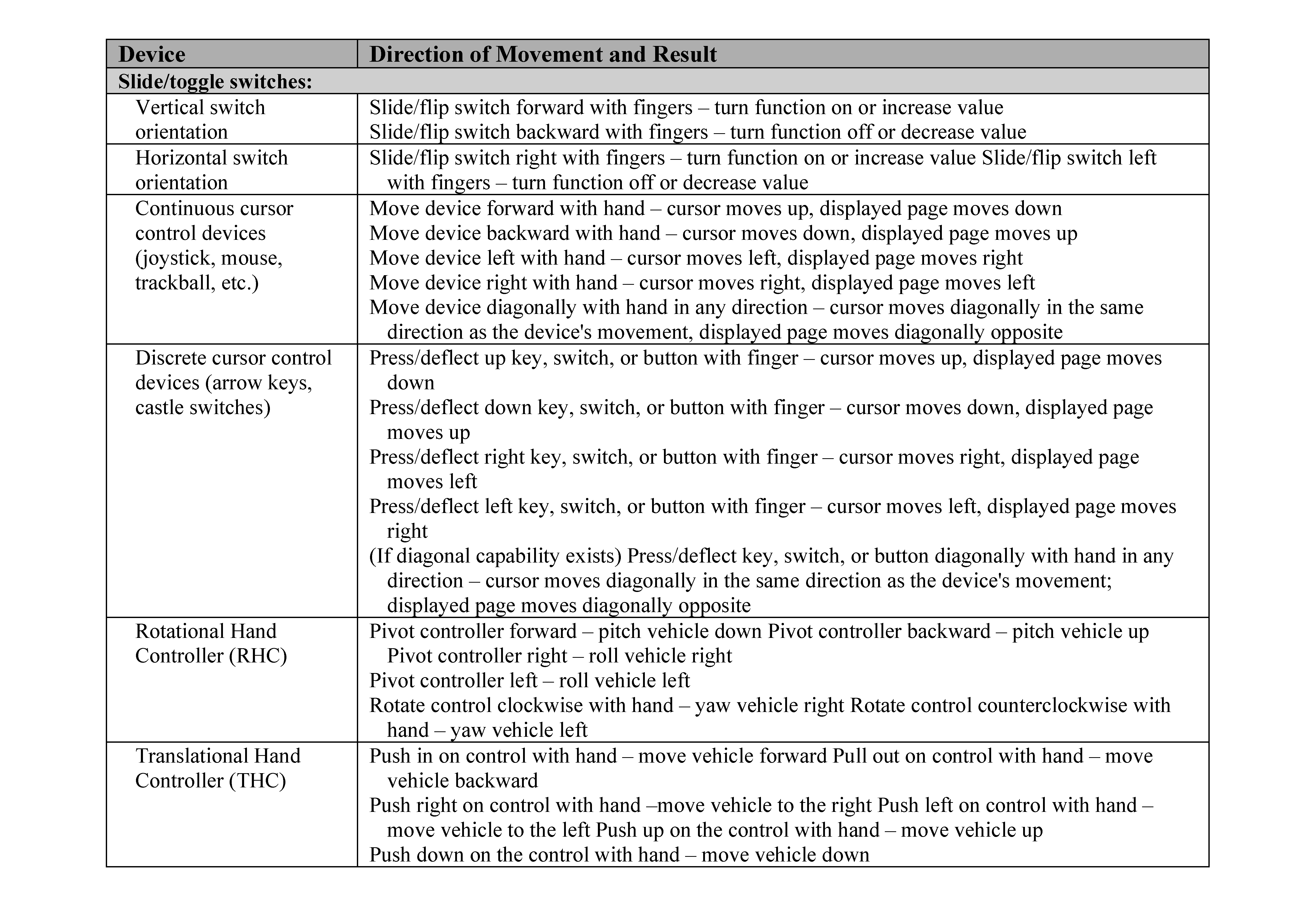
10.4.1.2 Display and Control Movement Compatibility
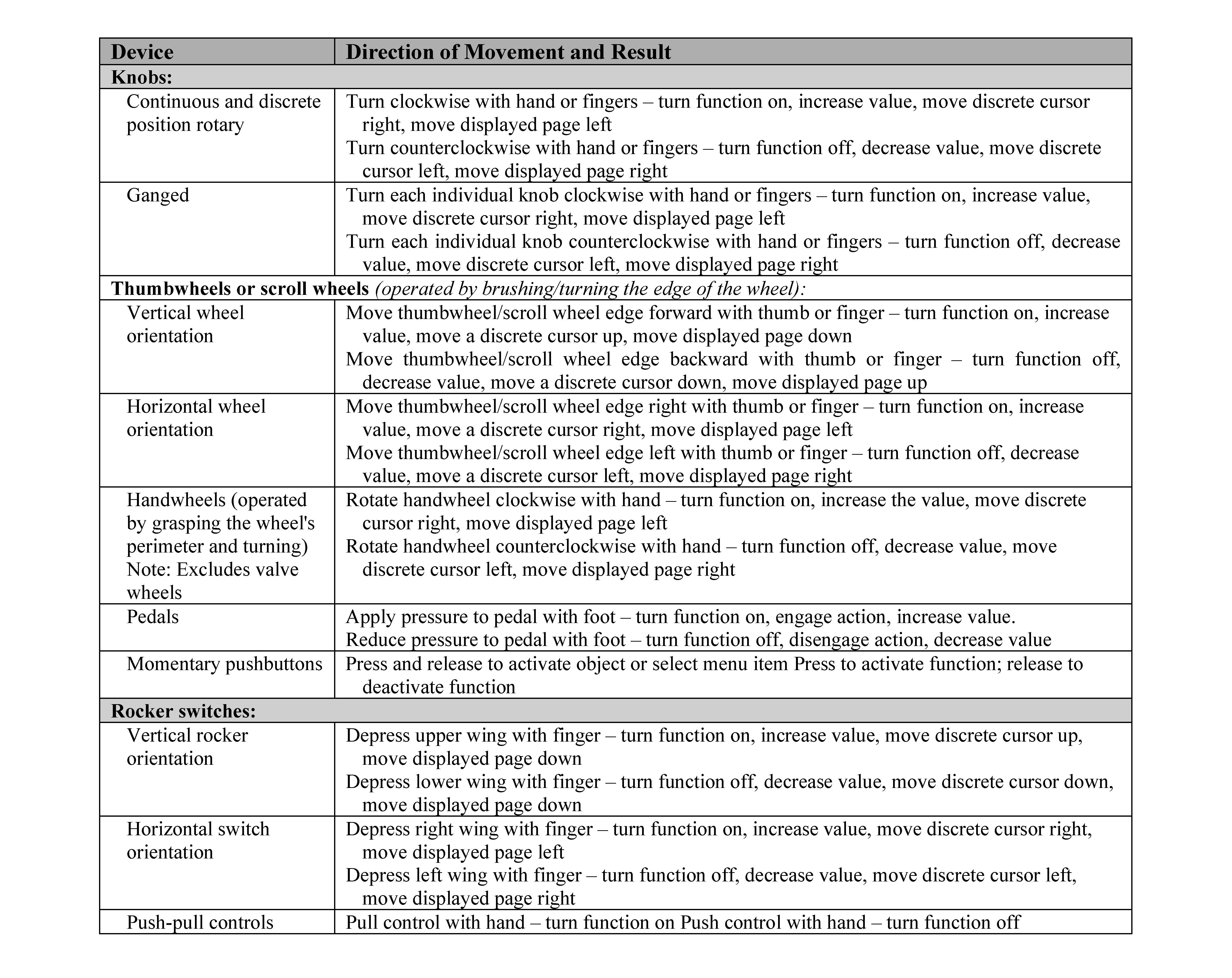
[V2 10034] Displays shall be compatible with control movement and the resulting system response as defined in Table 10.4-1—Hardware and Software Controls.
[Rationale: Control-display compatibility is a widely used design principle to help ensure the relation between input direction and system responses is intuitive and easy to perceive. This helps ensure that when a control is used, system response is easy to link and conforms to crew expectations (e.g., control motion to the right is compatible with clockwise roll, right turn, and increase in volume). Operator confusion may result if system responses are not compatible with input directions. If displays are overlaid on a visual (camera or direct view) scene, control movement is relative to this point of view.]
Table 10.4-1—Hardware and Software Controls
10.4.2 Displays
10.4.2.1 Simultaneous Display of Critical Information
[V2 10037] The system shall provide the display area to simultaneously present all critical task information required within the operator’s field of regard.
[Rationale: To ensure that critical tasks can be performed quickly, easily, and accurately, especially during critical mission phases, it is important to avoid scrolling or switching among several display pages and to avoid excessive head or body movement by the crewmember to view several displays. Criticality and critical task information is determined through a detailed task analysis.]
10.4.2.2 Color Coding Redundancy
[V2 10045] The system shall provide an additional cue when color is issued to convey meaning for critical information or for a critical task.
[Rationale: Redundant coding is required to accommodate the variability in people’s capability to see color under different lighting conditions and to increase the saliency of identification markings. Redundant cues can include labels, icons, and speech messages.]
10.4.2.3 Measurement Units
[V2 10046] The system shall use consistent units of measure that are displayed for each numerical value, or for each group of numeric values where the units are the same.
[Rationale: The use of consistent units of measure across a system minimizes crew training and the potential for conversion errors by crew and ground personnel, which can impact crew and vehicle safety. Measurement units are to be identifiable with the correct magnitude and scale. This ensures correct decision making when comparing or using these units in some other way.]
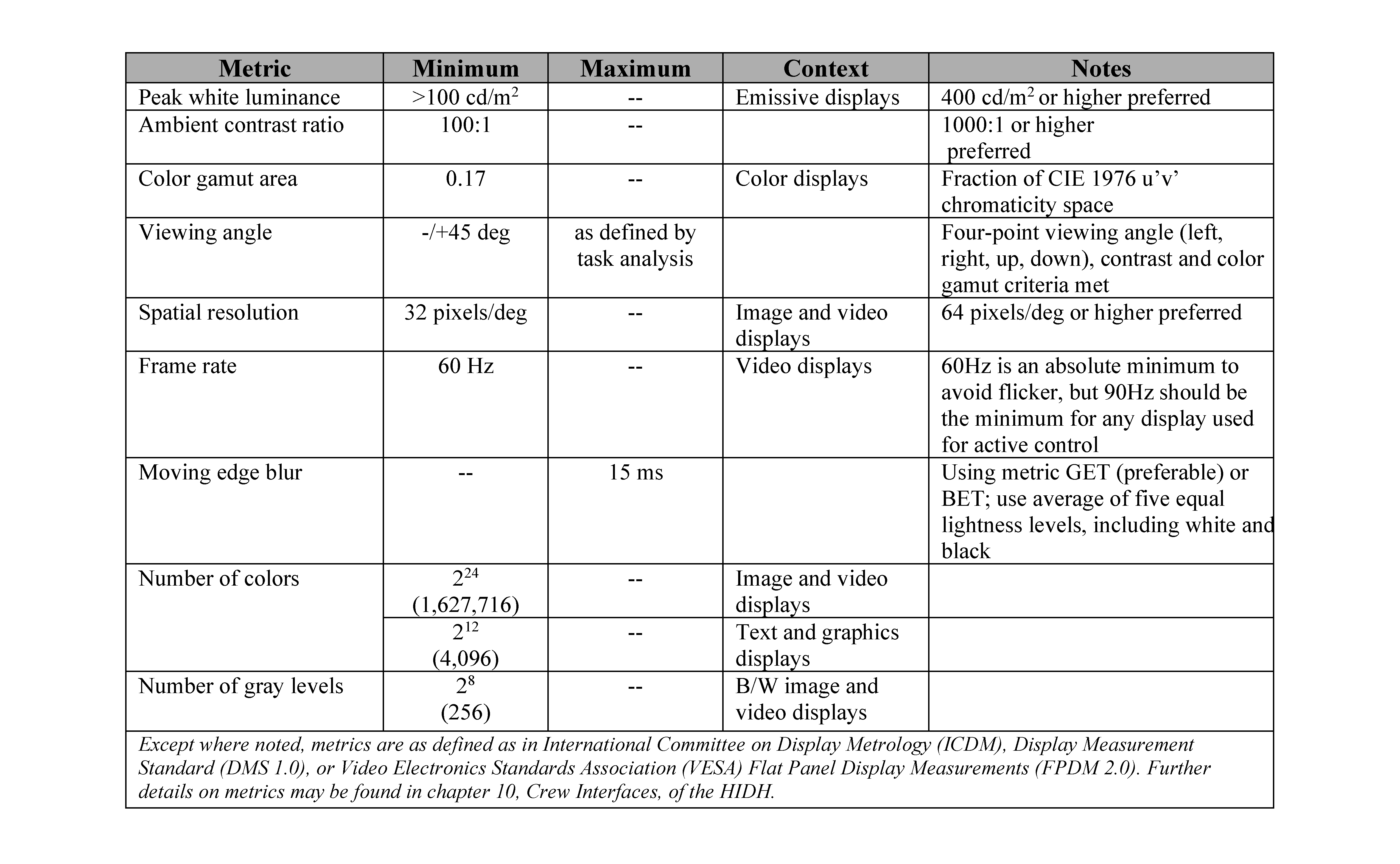
10.4.2.4 Visual Display Parameters
[V2 10048] The system shall provide IVA displays that meet the visual display requirements in Table 10.4-2—Visual Display Parameters.
[Rationale: Legibility of displayed information is important for the timely and accurate processing of information. To ensure legibility and visual quality, displays are to have sufficient spatial and temporal resolution, brightness, luminance contrast, and color gamut, taking into account the ambient illumination, glare, reflections, vibration, and distance, position, and orientation of the display relative to the crewmember.]
Table 10.4-2—Visual Display Parameters
10.4.2.5 Indicator Light Characteristics
[V2 10201] The system shall implement indicator lights that meet the characteristics shown in Table 10.4-3—Indicator Light Characteristics.
[Rationale: This requirement promotes consistency across indicators and the use of color for alerts, reducing the risk of misinterpretation and error. Care must be taken to ensure colors are distinguishable (e.g., yellow is not confusable with green).]
Table 10.4-3—Indicator Light Characteristics

10.4.3 Labels
10.4.3.1 Label Provision
[V2 10060] The system shall provide labels for the crew to identify items, interpret and follow nominal and contingency procedures, and avoid hazards.
[Rationale: Crew interface items are to have identifiers (labels) to aid in crew training and error-free operation. Labels reduce memory load and improve accuracy of tasks. This includes identification of emergency equipment and procedures. The Labeling Plan identifies which interfaces require labels.]
10.4.3.2 Label Location
[V2 10063] The system shall provide labels that are positioned on or directly adjacent to the item they are labeling.
[Rationale: Labels that are placed far from items they intend to label can result in the crew missing their association or misidentifying items. This can slow down task performance and may cause errors.]
10.4.3.3 Label Font Height
[V2 10066] The system shall provide labels that have a minimum font height of 12-point or 0.4 degrees in expected operating positions.
[Rationale: Labels are to use a large enough font size to ensure legibility. Small fonts can make labels difficult to perceive by the crew, consequently increasing the time needed for item identification. Font height in degrees refers to the angle subtended at the eye by the height of an uppercase letter in the font. The font height given is a minimum. The font may have to be larger for readability when taking into account the ambient illumination, glare, reflections, vibration, position, and orientation of the label relative to the crew.]
10.4.4 Controls
10.4.4.1 Out-of-View Control Identification
[V2 10068] Controls that are intended for out-of-view operation shall be spatially or tactually distinct from one another.
[Rationale: When the crew inadvertently operates the wrong control, serious errors can result. Controls designed to be out of view while being operated are to be spaced or shaped/textured such that the control can be identified with a pressurized gloved hand without line of sight. This would include controls for vehicle operation, as well as other controls (e.g., seat positioning). It has been shown that human operators can use simple tactile coding to reliably distinguish between items.]
10.4.4.2 Hazardous Control Coding
[V2 10069] The system shall provide coding for hazardous or irreversible controls that are distinguishable from non-emergency controls.
[Rationale: Coding for emergency controls allows the operator to distinguish them from other controls. This will help the operator react faster in an emergency situation. It has been shown that operators react more quickly to simple coding such as colors and pictures than they do to written labels. A task analysis defines the list of emergency controls. Guidance on the development of hazard, caution and warning, and emergency use labels and coding can be found in Section 4.13 of JSC 65995, Commercial Human Systems Integration Processes (CHSIP).]
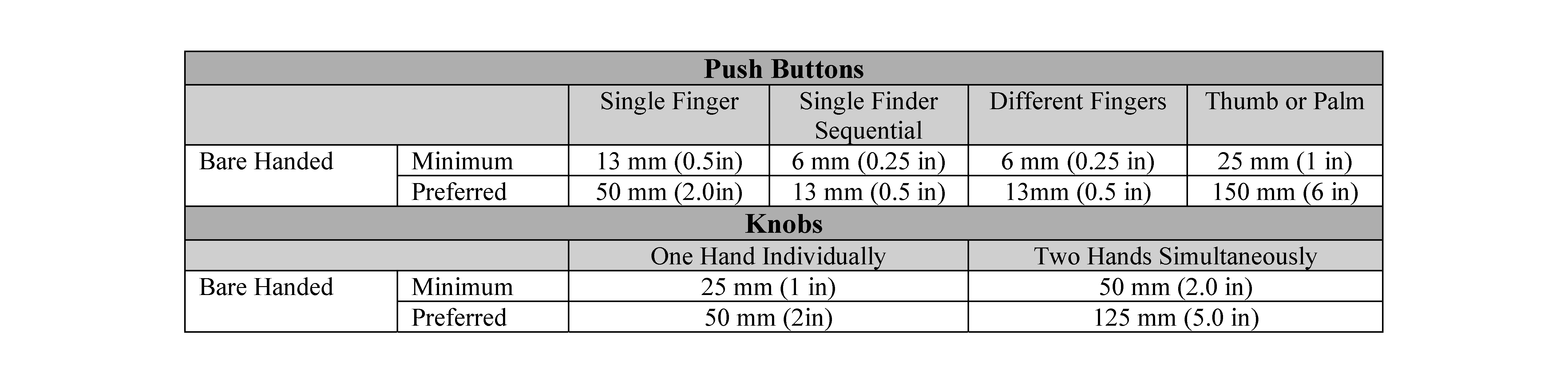
10.4.4.3 Control Spacing
[V2 10070] The system shall provide spacing between IVA controls that meets the criteria in Table 10.4-4—Control Spacing.
[Rationale: The spacing between controls is to be appropriate for the type of control and operating condition. Inadequate separation can cause errors during control operation. Preferred separations are to be used unless space does not allow, then controls must be at least the minimum distance apart or separated by guards. Push buttons are used if a control is needed for momentary contact or activation. They are not used when the status of a function must be indicated by position of its control. Knobs are used if low force or precise adjustment of a continuous variable is required. Other types of controls and specifications not listed in the table can be found in the Human Integration Design Handbook (HIDH) or HF-STD-001B FAA Human Factors Design Standard.]
Table 10.4-4—Control Spacing
10.4.4.4 Connector Spacing
[V2 10157] The system shall provide spacing between IVA connecters that is at least:
- 25 mm (1 in) if operated with bare fingers,
- 32 mm (1.25 in) if operated with unpressurized gloved fingers,
- 64 mm (2.5 in) if must be “gripped firmly” with multiple fingers.
[Rationale: A connector is a piece of hardware that joins or attaches lines or cables to other lines or cables or to units of equipment. The term is used rather loosely to refer to either of the two parts that mate with each other and to the plug that mates with a receptacle. Inadequate separation between connectors can prevent all users from successfully mating or demating connectors. Distance between connectors is measured from the outermost portion of the connector, including any shell, clamp, cover, or shield that exists.]
10.4.4.5 Control Operation Supports and Restraints
[V2 10073] The system shall provide body or limb supports and restraints that enable accurate crew control of applicable interfaces and prevent inadvertent control inputs during expected gravity, acceleration, and vibration conditions.
[Rationale: During expected gravity acceleration and vibration conditions, the accuracy of gross limb movements is compromised, and support of the operator limbs is required for control tasks. Control action under these conditions is to be limited to hand and wrist motions alone.]
10.4.4.6 Moderate-g Control Configuration
[V2 10158] The system shall place controls used during accelerations between 2g and 3g so that the operator can make control inputs via hand/wrist movements and forward reached within +/- 30-degree cone.
[Rationale: Between 2g and 3g, controls must be operable by a restrained crewmember. In a study of reaches under Gx loading with veteran astronauts and aviators as subjects, suited subjects on average exhibited little impact at 2g but did show a 6% reduction in maximum forward reach displacement at 3g (Schafer & Bagian, Aviation, Space, and Environmental Medicine, 64: 979, 1993). Hence, between 2g and 3g, even with highly motivated and trained subjects, reaches will begin to show errors above 2g, and so control actions are to be limited to hand/wrist motions or forward arm movements within a +/- 30-degree cone (apex at the shoulder joint, aligned with the axis of acceleration). For tasks requiring rapid response times or for deconditioned crew, a more conservative approach with controls placed to minimize reach – allows for an improved crew ability to operate the control. Awkward shoulder/elbow postures, which could result from reaches to displays/interfaces at close distances, increase fatigue and errors resulting in high crew workloads that could exceed workload requirements. Additionally, proper arm/wrist support are to be provided such that operation of any hand controller is not hampered by g-loading.]
10.4.4.7 High-g Control Configuration
[V2 10159] The system shall place controls during accelerations above 3g so that the operator can make control inputs via hand/wrist movements without reaching.
[Rationale: Above 3 g, controls must be operable by a restrained crewmember and the accuracy of gross limb movements is compromised. Therefore, control action under these conditions is to be limited to hand and wrist motions alone. Arms/legs will require proper support and/or restraint to allow for accurate control input during elevated g conditions and to prevent inadvertent control inputs during high-g nominal and abort scenarios. In a study of reaches under Gx loading with veteran astronauts and aviators as suited subjects, there was a 6% reduction in forward reach displacement at 3 g, 18% at 4 g, and 32% at 5 g (Schafer & Bagian, Aviation, Space, and Environmental Medicine, 64: 979, 1993). Proper arm/wrist support are to be provided such that operation of any hand controller is not hampered by g-loading.]
10.4.4.8 Manual Piloting Control Latency
[V2 10076] The system shall provide controls for the execution of manual piloting such that latencies will be less than 100ms for high gain tasks and less than 200ms for low gain piloting tasks.
[Rationale: State changes associated with the operation of a control are to have minimal time delays such that handling qualities of the vehicle are not negatively impacted. If the inception of a controller and the pilot’s observation of its system response occur with a significant latency, it is difficult to identify whether the operation of the control had the intended effect within sufficient time constraints, leading to adverse handling qualities and possibilities of adverse outcomes such as pilot induced oscillation. For piloting tasks, such lags must not result in pilot induced oscillation and support handling qualities as required by [V2 10004] Handling Qualities. High gain tasks are those for which temporal demands and task urgency are key drivers of task success or failure (such as lunar landing), while low gain tasks are those which place lower temporal demands on the crew (such as RPODU). The acceptable levels of latency presented in this requirement are consistent with MIL-STD-1797A – Flying Qualities of Piloted Aircraft, and as described by Effect of Time Delay on Flying Qualities: An Update (R.E. Smith and S.K. Sarrafian, Journal of Guidance, Control, and Dynamics, Vol 9, No. 5. 1986).]
10.4.4.9 Manual Piloting Control Latency Variability
[V2 10160] The system shall provide controls for the execution of manual piloting such that latencies have a minimum variability.
[Rationale: If the latencies (time delays) that exist are not consistent and are highly variable during the execution of a task, it can be extremely difficult for crew to mitigate or adapt to the effects of such delays as the inconsistency makes adaptation almost impossible.]
10.4.4.10 Control Resistive Force
[V2 10077] Control resistive force shall prevent unintended drifting or changing of position.
[Rationale: Controls must resist drifting or changing of position due to normal operational forces such as gravity on planetary surfaces or g-loading during maneuvering or station keeping for vehicles and space based-platforms.]
10.4.4.11 Detent Controls
[V2 10078] The system shall provide detent controls when control movements occur in discrete steps.
[Rationale: Mechanisms that provide control feedback to crewmembers are to be based on the amount of the movement applied to the control. This is usually provided using auditory and haptic feedback.]
10.4.4.12 Stops Controls
[V2 10079] The system shall provide stops at the beginning and end of a range of control positions, if the control is not required to be operated beyond the end positions or specified limits.
[Rationale: Limits within which controls can be operated are to be obvious to the crew by the provision of easy-to-perceive stops in the mechanism of the controls. Failure to include stops can result in increased operations time, as the operator may needlessly continue to turn a dial after it has reached its functional end point.]
10.5 Audio, Communication, and Video Systems
10.5.1 Audio Systems
10.5.1.1 Intelligibility of Electronically Stored Speech Messages
[V2 10052] Electronically stored speech messages from audio displays shall have 100% intelligibility and discriminability between the ensemble of different messages the audio display is programmed to produce (as measured under realistic background noise conditions and at locations where the display will be used).
[Rationale: Some audio displays and alarms express their messages using electronically stored speech. The consequences of misunderstanding these messages can result in lost time and possible missed or false alarms and can ultimately be a critical safety issue.]
10.5.1.2 Reverberation Time
[V2 10057] The system shall provide a reverberation time of less than 0.6 seconds within the 500-Hz, 1-kHz, and 2-kHz octave bands.
[Rationale: This 0.6 s reverberation time requirement limits degradation of speech intelligibility to no more than 10% for ideal signal-to-noise ratios of >30 dB or 15% for a signal-to-noise ratio of 3 dB (Harris, 1997).]
10.5.2 Communication Systems
To ensure optimal team collaboration in exploration missions, it is essential to design communication systems that provide an accurate, comprehensive, real-time understanding of the current situation and to implement tools that enable team members across the multi-team system of crew and ground to communicate and collaborate effectively. This is particularly critical when teams are operating in the presence of communication transmission delays and intermittent transmission. Communication systems process information to and from the crew and may consist of the following media: voice/audio, video, text, and data.
10.5.2.1 Communication System Design
[V2 10083] Communication systems shall be designed to support coordinated and collaborative distributed teamwork.
[Rationale: To ensure optimal team collaboration in exploration missions, it is essential to design communication systems that provide an accurate, comprehensive, real-time understanding of the current situation and to implement tools that enable team members across the multi-team system of crew and ground to communicate and collaborate effectively. This is particularly critical when teams are operating in the presence of communication transmission delays and intermittent transmission. Communication systems process information to and from the crew and may consist of the following media: voice, video, text, and data.]
10.5.2.2 Communication Capability
[V2 10084] The system shall provide the capability to send and receive communication among crewmembers, spacecraft systems, and ground systems to support crew performance, behavioral health, and safety.
[Rationale: Communication capabilities are necessary to enable information exchange to accomplish tasks efficiently, to maintain crew physical and behavioral health, and to ensure crew safety. The capability to send and receive information among crew (IVA and EVA), Earthbased mission control, orbiting vehicles, planetary habitats, extraterrestrial surface transport vehicles, robotic systems, and other systems is to be supported as required by the task analysis for the particular Design Reference Mission (DRM). Communications can include voice, text, video, telemetry, and other formats, depending on the needs as determined by a task analysis.]
10.5.2.3 Communication Speech Levels
[V2 10085] Audio communication systems shall allow crew to communicate with one another and with the ground at normal speech levels and with expected background SPLs.
[Rationale: When crewmembers and ground personnel use the voice communication systems, they are to be able to do so using their normal level of speech, rather than having to raise their voices to higher levels. Higher voice levels distort sounds, make speech less intelligible, and are more strenuous to keep up for longer periods.]
10.5.2.4 Speech Intelligibility
[V2 10091] For critical communications, the system shall ensure 90% English word recognition, using ANSI/ASA S3.2-2009, Method for Measuring the Intelligibility of Speech over Communication Systems.
[Rationale: Voice communication is to be perceived accurately. If messages are perceived with errors or low precision, important information may be missed; therefore, crew may make errors in tasks, and their safety may be jeopardized. To ensure speech intelligibility, the communication system must take into account operational parameters (including frequency, dynamic range, noise cancelling and shields, pre-emphasis, and peak clipping), appropriate background sound levels and architectural acoustical characteristics for both transmitter and receiver area, operating controls and procedures (including volume, squelch, natural language, acknowledgement feedback, and muting), and transmitter and receiver configuration (including headsets, microphones, air bone conduction, and bone conduction). Communication is optimized by considering all parameters needed for speech intelligibility. Background noise, reverberations, and other acoustic phenomena are not to interfere with crew communications. High levels of background noise can make audibility of speech difficult. High reverberations interfere with intelligibility. Procedures are to use natural language. Note: [V2 10091] Speech Intelligibility in this NASA Technical Standard is not meant to apply to speech recognition software.]
10.5.2.5 Private Audio Communication
[V2 10093] The system shall provide the capability for two-way private audio communication with the ground.
[Rationale: Private communication capabilities are to exist for the crewmember to discuss topics such as family, health, and medical issues with the ground in private.]
10.5.3 Video Systems
Video communications systems are communications channels designed to convey visual information such as camera video, animated graphics, and photographic images.
10.5.3.1 Video Communications Visual Quality
[V2 10094] Video communications shall employ digital encoding or alternate coding of equivalent visual quality.
[Rationale: The quality of the video communications is to be appropriate for correct information transfer. Bad image quality can be misinterpreted, can cause communication problems, and can increase time needed to accomplish tasks.]
10.5.3.2 Video Communications Spatial Resolution
[V2 10095] Video communications shall provide sufficient spatial resolution (width and height in pixels) to accomplish relevant tasks.
[Rationale: The resolution of video is to be appropriate for the task that it is intended to serve, so that errors related to artifacts of low resolution and delays in task completion are avoided.]
10.5.3.3 Video Communications Temporal Resolution
[V2 10096] Video communications shall provide sufficient temporal resolution (frames/s) to accomplish relevant tasks.
[Rationale: The temporal resolution of a communication is to be appropriate so as to perceive human speech, motion, and object motion through the video. Inappropriate resolution can make these more difficult or impossible, thus causing difficulties in information transfer.]
10.5.3.4 Video Communications Color and Intensity
[V2 10097] Video communications shall provide sufficient color and intensity levels to accomplish relevant tasks.
[Rationale: Color and intensity are to be transmitted appropriately. Inappropriate color and intensity in video communication may cause misidentification and misinterpretation of information, thus causing errors and problems in task completion.]
10.5.3.5 Video Communications Bit Rate
[V2 10098] Video communications systems shall support bit rates high enough to ensure that compression artifacts are as low as reasonably achievable.
[Rationale: The compression method and level used for video communication are not to introduce excessive visible artifacts. Artifacts can hinder information transfer and can cause communication difficulties.]
10.5.3.6 Audio-Visual Lag Time
[V2 10099] Communications systems that carry sound and video that are intended to be synchronized shall ensure that the sound program does not lead the video program by more than 15 ms or lag the video program by more than 45 ms.
[Rationale: The video and associated audio time lag can cause perceptual difficulties for the crew. When listening to human speech, even small lags between audio and video can be noticeable and disturbing.]
10.6 Automated and Robotic Systems
Automation is the use of machines or computers to perform tasks to reduce crew workload, increase productivity, or decrease risk in operations that the crew cannot safely perform. Systems are to have automated or robotic solutions that can perform tasks where (1) crew cannot respond as quickly, precisely, or repeatedly as necessary; (2) crew cannot physically complete the task; or (3) using automation/robotic solutions reduces crew risk exposure (e.g., high radiation environments, limited life support availability). Automation function needs to be designed around human roles for specific tasks, with the human operator having ultimate authority. In almost all cases, the human should remain in command, which essentially means they have the power to override or shut down the system. The allocation of responsibilities between humans and automation should seek to optimize overall integrated team performance. Design requirements are to ensure that decision support is available to crew. The human operator needs to understand why the automated system is recommending actions, and the consequences of those actions, to make an informed decision. Decision aids could also help with simulating the course of action chosen by the expert. Automated and robotic systems should have preventive/safety measures in place, such as mechanical constraints, threshold set points, automatic shutoffs, and emergency stops to ensure that they cannot negatively impact the mission, hardware, or crew health and safety. Robotic systems with internal safety checks that recognize and avoid unsafe conditions, e.g., excessive speed, force, and torque, are more likely to achieve mission success. This applies to robotic systems both inside and outside spacecrafts. For more information regarding this subject, see Chapter 10, Crew Interfaces, of the Human Integration Design Handbook (HIDH). Design requirements are to ensure that different levels of automation are available, depending on which level best suits the task/situation. While higher levels of automation can result in increased crew performance (e.g., fewer errors) and lower workload, they can also result in poorer SA and loss of crew skills (Onnasch, et al, 2014). This tradeoff should be taken into consideration when designing automated and robotic systems. Task analysis in conjunction with function allocation evaluations should determine the appropriate level of automation, and a trade analysis should be conducted. Systems are not to be so reliant on automation that human operators cannot safely recover from emergencies or operate the system manually if the automation fails. It needs to be clear whether the human operator or the system is supposed to perform a particular task at a specific time. The operators need to be able to determine and affect what level of automation the system is operating in, as well as which processes are being automated. The analysis will determine cases where alerting may be required when automation takes control from human operators or switches to a higher level of automation. The below technical requirements do not apply when time to effect is too short to allow successful human intervention.
10.6.1 Automation System Status Provision
[V2 10161] The automated system shall provide the human operator with the following information:
- system state (e.g., position, location, hazardous condition, running, paused, faulted,completed, overridden, stopped, readiness)
- projection of future state, including failure or decrements in performance (e.g.,battery power versus traverse distance and assessment of uncertainty in projection of future state) and mode (e.g., Full/Partial/Manual/Test)
- system health
- configuration information (e.g., setup/input parameters, initial conditions, and terminating conditions)
[Rationale: The human operator needs to maintain situation awareness to work effectively with automation, calibrate trust in the system, and avoid errors. The operator needs access to information about system health and the projection of system state to understand how well automation is likely to perform and calibrate trust (knowing which situations can rely on automation, which situations require increased oversight by the operator, and which situations are inappropriate for automation). The operator needs to be aware of automation performance decrements or failures to be ready to resolve the situation or take over the task.]
10.6.2 Automation Mode Change Notification
[V2 10162] The system shall notify the human operator of mode changes of any safety-critical operations.
[Rationale: Conspicuous indication of the current mode will help prevent operators from making mode errors (i.e., taking an inappropriate action or failing to take a needed one, caused by thinking the system is in one mode when it is in another mode). Notification by displays or other means gives the operator the ability to prepare for a mode change or to adjust behavior to a new mode environment. Designers need to define the best methods to inform and notify humans before the change takes place and gain when it happens.]
10.6.3 Automation Data Availability
[V2 10163] Automated or robotic systems shall record and make available operational and performance data to both crew and ground support personnel.
[Rationale: Data, such as telemetry, states, modes, etc., should be saved and made available to operators both in space and on ground. Historical performance information on automated processes can aid in understanding current trends and events and help inform needed actions. Significant event data can aid in troubleshooting future issues.]
10.6.4 Automation System Responsibility Delineation
[V2 10164] Automated systems shall indicate whether a human operator or system is expected to perform a particular operation at a specific time.
[Rationale: A clear, salient delineation of the responsibilities of the human and the automated system is important to ensure that the operator performs the appropriate actions at the appropriate time. Transitions between automated and human operator control need to be performed under well-defined procedures that specify system state before and after the transition. Previous close calls in spaceflight operations have occurred because the human operator delayed in taking particular actions at specific times. Specific indicators will help support human-automation interaction that avoids errors of omission and commission.]
10.6.5 Automation and Robotics Override and Shut-Down Capabilities
[V2 10165] Automated or robotic systems shall provide the human operator the ability to safely override and shut down automated systems or subsystems.
[Rationale: The system is to allow the human operator the ability to override or shut down automated or robotic systems if it is determined that these systems present a risk, or if redirection of activities is needed. The human is to remain in ultimate control of the vehicle at all times throughout a mission. It is essential that the override or shut down capability is performed safely, i.e., avoids inadvertent harm to crew and vehicle.]
10.6.6 Automation System Configuration
[V2 10166] Automated or robotic systems shall provide the human operator the ability to modify system configuration within the safety and performance limits of the system.
[Rationale: In a human-automation team, the human operator must remain in control and thus needs to be able to modify automation configuration information, including setup/input parameters, initial conditions, and terminating conditions. There are some configurations that must not be allowed to be manipulated due to performance or safety considerations, which are specific to each system.]
10.6.7 Range of Control
[V2 10167] Automated or robotic systems shall provide the human operator with a range of control options that accommodates the expected operating conditions.
[Rationale: Automated or robotic systems are expected to be operated in different manners; for example, these highly flexible systems will be controlled directly (i.e., manual control) or commanded remotely (i.e., supervisory control). The multiple options associated with these highly flexible systems must be operable via a range of controls available to the human operator.]
10.6.8 Automation Failure Recovery
[V2 10168] The automated or robotic system shall enable the human operator to safely assume control of the system if a failure occurs or there is an inability to function (e.g., beyond designed ability).
[Rationale: If a failure or inability to function happens, the information provided by the system is to enable the human operator to collect confirming or exclusion evidence to decide on a safe course of action.]
10.6.9 Decision Support
[V2 10169] The automated or robotic system shall allow the human operator to determine when to use a decision aid and which decision aiding strategy to employ.
[Rationale: The human operator is to remain in control and has the authority to decide when and how to use decision aids. Decision aids are to provide pertinent data or information, analysis, and/or suggested solutions for continued operations. The system ultimately needs to enable the operator to make those decisions, whether or not it is the operator that acts on them.]
10.6.10 Decision Aid Clarity
[V2 10170] Decision aid systems shall provide explanations and rationales, and consequences of potential actions.
[Rationale: The human operator needs to understand why the automated system is recommending actions, and the consequences of those actions, to make an informed decision without significantly disrupting the operator’s task. This is key to maintaining situation awareness, as well as calibrating trust. Decision aids are key to problem diagnosis, and hence, automation transparency is an essential attribute for these systems. Decision aids can also help with simulating the course of action chosen by the expert. The aid can help identify weaknesses in the plan and provide improvement options. When developing decision aids, it is important to base concepts on human factors principles, while considering the flow of information and the level of detail that it needs to contain.]
10.6.11 Decision Aid Limitation Notification
[V2 10171] Decision aids shall notify the human operator when a problem or situation is beyond the aid’s capability.
[Rationale: The human operator needs to be made aware when a decision aid is unable to assist with a decision due to lack of information or limitations in design so that information can be provided, or other avenues can be explored in a timely manner (e.g., call ground).]
10.6.12 Automation Safe Mode
[V2 10172] The automated or robotic system shall take protective action (e.g., avoidance maneuver, protective stop) or request that the operator safely take control if the system’s operational safety threshold is exceeded.
[Rationale: Protective actions include avoidance maneuvers, protective stops, and “return home” if the human operator can no longer communicate or command the system. The transition to operator control needs to occur safely and minimize harm to the operator and vehicle.]
10.6.13 Safety Default
[V2 10173] The automated or robotic system shall maintain safe operations if the human operator does not assume control when requested.
[Rationale: In a failed transfer of control from the automated system to the human, the automated system experiencing degraded performance must take appropriate measures to remain in a safe state, including alerting the operator of the degraded state and transfer of control.]
10.6.14 System Initiation
[V2 10174] Autonomous robotic systems shall be initiated only by human operators, including restart after an emergency or protective stop.
[Rationale: The human operator is to remain in control and must authorize a system restart after an emergency or protective stop.]