


This article is from the 2016 NESC Technical Update.
For more than 40 years, Dr. Ivatury Raju, NASA Technical Fellow for Structures, has watched structural analysis grow by leaps and bounds. Giant mainframe computers used to plug away for months to generate sophisticated finite element analyses (FEA). Today, desktop computers can produce FEA results with complex 3D models in a matter of days. But with this progress, Dr. Raju and the structures greybeards are witnessing some alarming and worsening trends.
Many early-career engineers, proficient in the use of modern computers, computing engines, and complex software packages such as NASTRAN, ANSYS, and ABAQUS, are performing intricate FEA analyses without a sufficient background in engineering mechanics and are blindly accepting the quality of the results. Dr. Raju’s concern reached a tipping point when he read a comment on a popular social networking site for scientists and researchers: The model exactly looks like the part. The analysis ran to completion without any errors; the results are displayed as contour plots in color — how could the analysis and results be wrong?
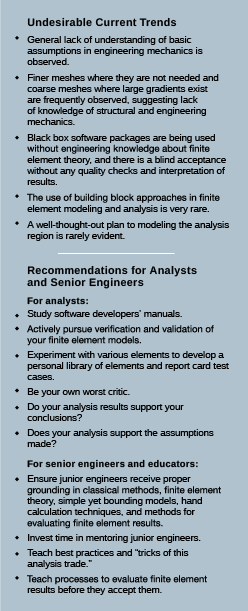
“This analyst believed that the results displayed were satisfactory and accurate, and there was no need to check the results,” said Dr. Raju. “These questions point to inadequate formal training in engineering mechanics and FEA theory. That was the motivation for me to write this paper,” said Dr. Raju, who co-authored Some Observations on the Current Status of Performing Finite Element Analysis, with fellow engineers Dr. Norman Knight and Dr. Kunigal Shivakumar. “We had to raise this flag,” he said. The paper has allowed Dr. Raju and his coauthors to draw attention to some of these trends and offer guidelines and suggestions to help overcome them. (See Sidebar: Undesirable Current Trends).
Adept at meshing — but not at modeling
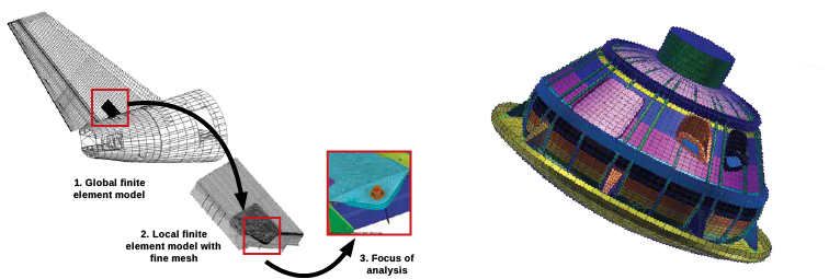
What Dr. Raju has noticed over the last few years is that early-career engineers, analysts, and other users of FEA software are quite adept at performing swift and accurate meshing of components for complex aerospace structures. But not all of those users have mastered the art of modeling. The authors point out that meshing requires expertise in using a software package, while modeling involves expertise in idealization of the structure and in understanding the structural response to loads and restraints.
Dr. Raju said users need to understand the implications associated with selecting one element type over another. “In a way, modeling involves knowing the answer before you get it. So unless you have experience, you don’t know where to put the fine mesh,” he said. Choices associated with the element shape function order (linear, quadratic, p-versions), element continuity requirements, placement of mid-side nodes, and facetted modeling of curved surfaces do influence the results.
Dr. Raju has seen similar issues with 3D modeling, with 3D mesh models currently more common than plate or shell models. “A 3D model has its own difficulties,” he said. Computer-aided design packages treat all geometry as 3D, he notes in the paper. Engineering judgment is necessary to extract representative planes out of the 3D model so that accurate shell models can be built. Lacking those judgment skills, early-career engineers are relying on the automesh button, which may generate large numbers of solid elements, making it more difficult to interpret results for bending, transverse shear, and other quantities.
And when it comes to bolts and bolt modeling, “There are numerous ways you can model bolts,” said Dr. Raju. “And any way you do it has its own pitfalls. So you have to know what you are doing.” For example, analysts are simply smearing the thickness of the fastened parts together and ignoring the discrete bolts; introducing discrete constraints or a beam element at every fastener location and ignoring features of the bolt; and including the fastener as one or more beams to simulate the bolt shank with sets of constraints to simulate the bolt head and nut. “Most analysts appear to be unaware of all of these pitfalls in bolt modeling and lack the knowledge of how a preloaded bolted joint works.”
The paper highlights many more examples of these trends and provides guidelines, suggestions, and tricks of the trade specifically aimed at analysts, senior engineers, and educators.
Reversing the trend
“The technology is moving at an astonishing rate,” said Dr. Raju, of the pace at which hardware and software is changing and improving. As for the engineers just starting their careers, computers are second nature for them, “but they don’t always know theory,” he said. “And they don’t always have time to learn everything. That’s why they need mentorship with senior engineers.” It’s one of the recommendations Dr. Raju and the authors direct toward senior engineers and educators as a way to help reverse this trend. “If they can see you in action, they will understand,” he said. “They can ask you questions.” (See Sidebar: Recommendations for Analysts and Senior Engineers).
For the engineers and analysts, the authors note that fundamental core engineering courses are key. And they suggest studying the software developers’ manuals. “The software developers who actually make the finite element codes are telling you the things you need to do,” said Dr. Raju. “They can tell you what to watch out for.”