


Quick Facts
Year Built: 1945
Historic Eligibility: National Register Eligible
Important Tests: Bell X-5, A-10 Thunderbolt II, F-18 Hornet, Advanced Manned Launch System and Flow Visualization
Year Demolished: 2009
History
In December 1938, the Special Committee on Future Research Facilities, chaired by Rear Adm. Arthur Cook, chief of the Navy Department’s Bureau of Aeronautics, recommended the construction of several new facilities at Langley geared toward investigating the special characteristics of military aircraft. One of these proposed facilities was a wind tunnel with a 7 X 10-foot diameter test section that could evaluate general aerodynamic effects at high speed, especially stability control problems.
The onset of World War II delayed plans for the new facility, but by 1943 the significant backlog of aircraft to be tested in Langley’s existing wind tunnels prompted the National Advisory Committee for Aeronautics (NACA) to authorize its construction in the new West Area granted by the War Department in 1939. The tunnel was designed by Langley engineers Thomas A. Harris and Charles J. Donlan and became operational in November 1945.
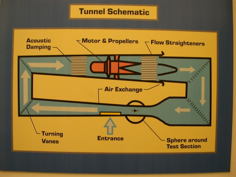
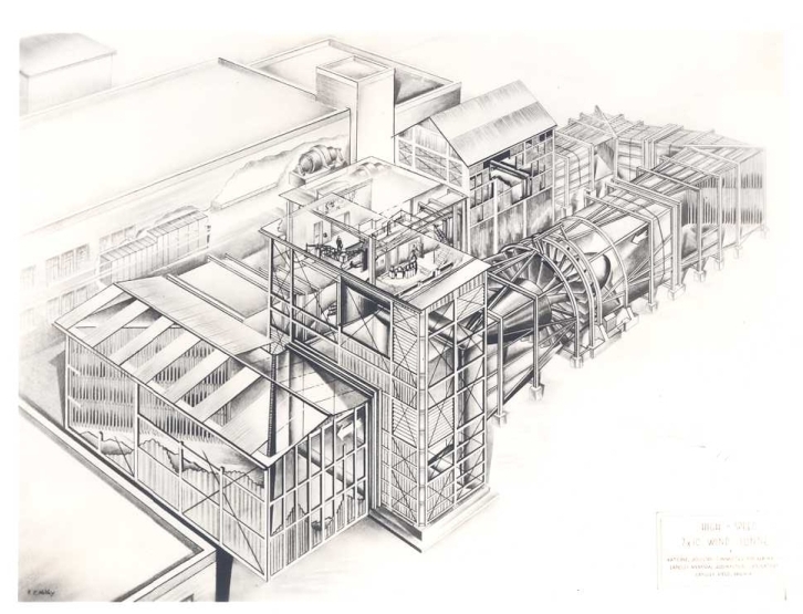
Completed at an initial cost of $2,052,000, and located adjacent to a low-speed tunnel of the same dimensions (7 X 10-Foot 300 mph Tunnel), the 7 X 10-Foot High Speed Tunnel (HST) had an atmospheric, single-return circuit with closed throat test section. The 18-blade fixed pitch wooden fan was powered by a 14,000 hp variable-speed electric drive system, and could develop a maximum speed of approximately 675 mph. Shop and office space and other auxiliary facilities were shared with the neighboring 300 mph Tunnel.
Although the 7 X 10-Foot HST did not incorporate any new or unique design features when first built, a number of subsequent modifications greatly enhanced its value in aerodynamic research. In 1946, a carefully designed “transonic bump” was installed. Air flowing over the bump was accelerated to the transonic range (up to and beyond the speed of sound, Mach 1, approximately 761 mph at sea level) even though the main airflow remained subsonic. Admittedly a crude modification, the bump nonetheless allowed engineers an early opportunity to experiment with transonic testing.
The tunnel once again was upgraded in the early 1950s in response to a design breakthrough spearheaded by Langley engineer Ray H. Wright. Aeronautical researchers had long recognized a significant flaw inherent in solid-walled test chambers, observing that the walls tended to suppress flow streamlines and produced deceptive aerodynamic effects. Reducing the size of models to allow for greater distance from the walls diminished the representative value of the data, while testing in open environments also produced unsatisfactory conditions. In the course of his research, however, Wright observed that this interference could be minimized by placing slots in the test section throat, a concept that came to be known as “slotted throat” or “slotted wall tunnel” design. With the interference problem neutralized, it was now possible for the tunnel to reach transonic speeds.
After considerable experimentation, Wright and his fellow engineers successfully converted two existing tunnels (the 8-Foot and 16-Foot High Speed Tunnels) to the new configuration in late 1950. Their success prompted the construction in 1953 of the 8-Foot Transonic Pressure Tunnel, the first to be built with the slotted throat design from its inception. That same year, the 7 X 10-Foot HST was retrofitted with slotted walls, increasing its top speed to Mach 1. In the mid-1950s, it was connected to the 35,000 hp compressor of the 16-Foot High Speed Tunnel, boosting its speed even further to Mach 1.2.
Throughout the Cold War era, the 7 X 10-Foot HST facilitated important research on a number of U.S. military aircraft and missiles. The Bell X-5, the world’s first airplane to vary the sweepback of its wings in flight, was tested here in the early 1950s. During the Vietnam War period, extensive testing was conducted on designs submitted by Grumman, Northrop, McDonnell, General Dynamics, and Fairchild Republic for the Air Force’s new Attack Experimental (A-X) Program.
More intensive testing of Fairchild Republic’s design in the early 1970s led to the refinement and eventual production of the A-10 Thunderbolt II close support and attack aircraft. Other craft tested in the 7 X 10-Foot HST included Grumman’s A-6E Intruder and EA-6B Prowler, the General Dynamics F-111 Aardvark and F-18 Hornet, as well as the proposed Advanced Manned Launch System, a two-stage, fully reusable launch system consisting of an unmanned glide-back booster and a manned orbiter.
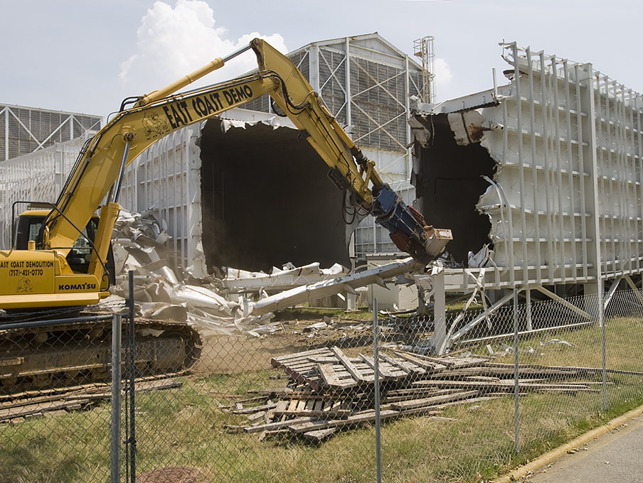
By the late 1980s, the 7 X 10-Foot HST had been altered so that it no longer was capable of Mach 1 airspeeds. However, Langley Research Center engineers continued to use the facility for important research, facilitated by the installation of a fiber-optic-based laser vapor screen (LVS) flow visualization system in 1990. In this system, fiber optics were used to deliver a laser beam through the plenum shell that surrounds the test section of the tunnel and to the light-sheet generating optics positioned in the ceiling window of the test section. Water was injected into the wind tunnel diffuser section to increase the relative humidity and promote condensation of the water vapor in the flow field around the model. The condensed water vapor was then illuminated with an intense sheet of laser light to reveal features of the flow field while being observed and documented with a video system. Experiments using this technology in the 7 X 10-Foot HST were conducted on a number of prototypes, including a generic reusable earth-to-orbit transport circular body vehicle (CBV). The facility was closed in 1994 and demolished in 2009.
Chronology of Langley 7×10 High Speed Tunnel
-
1938: The Special Committee on Future Research Facilities recommends the construction of a wind tunnel at Langley with a 7 x 10-Foot diameter test section
- 1943: The National Advisory Committee for Aeronautics (NACA) authorizes construction of the 7 x 10-Foot tunnel and construction is undertaken.
- 1945: The 7 x 10-Foot High-Speed Tunnel (HST) is completed and becomes operational in November.
- 1946: A “transonic bump” is installed, allowing early transonic testing.
-
1953: The tunnel is retrofitted with slotted walls, increasing its speed to Mach 1.
- The mid-1950s: Sparrow missile model tested.
- 1958-1959: Testing on models of hypersonic research plane X-15, which would contribute to the development of the Space Shuttle. NATO cooperative study of variable-sweep wing concept, leading to the development of outboard wing-pivot concept by Alford and Polhamus.
- 1958-1963: Mercury Project aims to put humans in orbit. Mercury Capsule model tested at Langley 7×10 HST in 1959.
- 1967: Needs of aircraft missions in Vietnam lead to the establishment of Attack Experimental (A-X) program. Studies by Polhamus, Henderson, and McKinney on transonic aircraft maneuverability, involving vortex-lift, and fixed and variable camber concepts.
- 1969 E. J. Ray leads a study at the tunnel of F-4 maneuver and buffet characteristics.
- 1971: Tests by Vernon Lockwood on powered model A-10 to determine aerodynamic characteristics in high-power conditions.
- The mid-1980s: Waggoner, Allison, and Sewall conduct studies to improve EA-6B military aircraft
- 1985: Fan blade failure
- 1990: A state-of-the-art fiber-optic-based laser vapor screen (LVS) flow visualization system is installed.
- 1994: Research at the tunnel is discontinued. Tours at the facility are conducted for visitors through 2001.
The NASA Technical Reports Server (NTRS) can be searched for examples of work conducted at the facility, such as the following:
- Lateral-control investigation of flap-type controls on a wing with quarter-chord line swept back 45 degrees, aspect ratio 4, taper ratio 0.6, and NACA 65A006 airfoil section. 1949
- Buffett and Static Aerodynamic Characteristics of a Systematic Series of Wings Determined from a Subsonic Wind-Tunnel Study. 1970.
- Effects of Spanwise Blowing on the Pressure Field and Vortex-Lift Characteristics. 1975.