


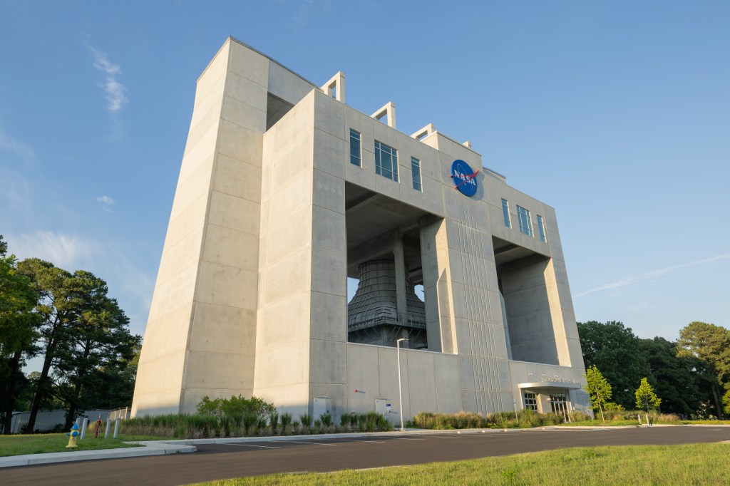


Structural Test Stands 4693 and 4697
Two new test stands are changing both the skyline at NASA’s Marshall Space Flight Center in Huntsville, Alabama, and the future of space exploration.
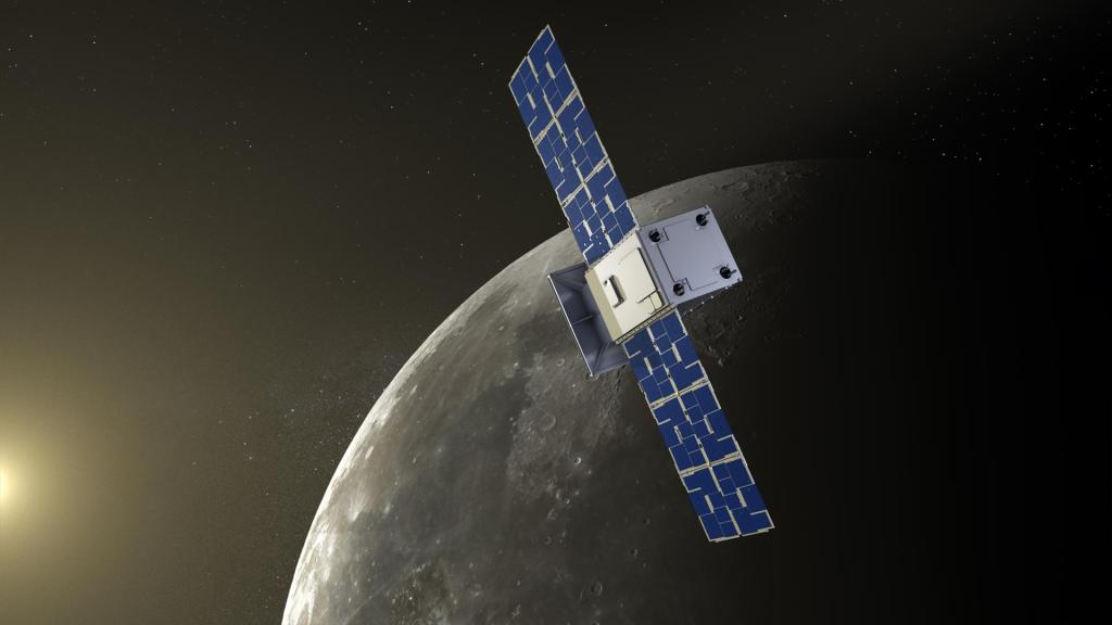
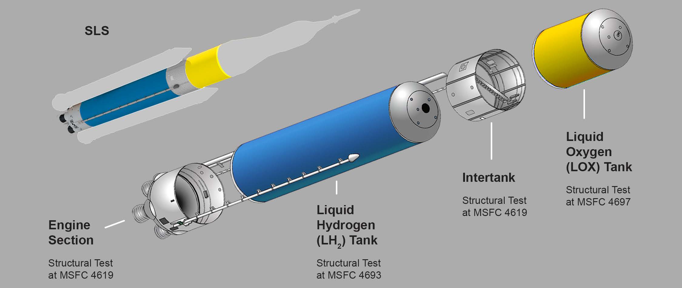
The first mission for Structural Test Stands 4693 and 4697 is to push, pull and apply pressure loads to the huge propellant tank structures and hardware designed for the core stage of NASA’s new heavy-lift rocket, the Space Launch System, subjecting them to the stresses they must endure during liftoff and flight. SLS will be the world’s most powerful rocket for human space exploration, able to launch astronauts in the Orion spacecraft on deep-space missions, including a journey to Mars.
Data collected from series of tests at Marshall will validate the accuracy and quality of the computer models and advanced manufacturing processes used to design and build those fuel tanks. While the size and cutting-edge capabilities of the two new test stands are critical to SLS development, the stands have been designed for adaptability to test the components of future large-scale rockets and systems for NASA, other government agencies or industry. The stands complement a broad range of test facilities already at Marshall and include features that facilitate the sharing of equipment and resources without major modification.
Getting the Data
Inside the SLS core stage, huge cryogenic fuel tanks, which are also primary vehicle structure, will feed more than 730,000 gallons of super-cooled propellant to four RS-25 engines at the rocket’s base. The Boeing Co., headquartered in Chicago, is developing the core stage, which is being built at NASA’s Michoud Assembly Facility in New Orleans. Test versions of the fuel tanks will be built there and carried by barge to Marshall for testing.
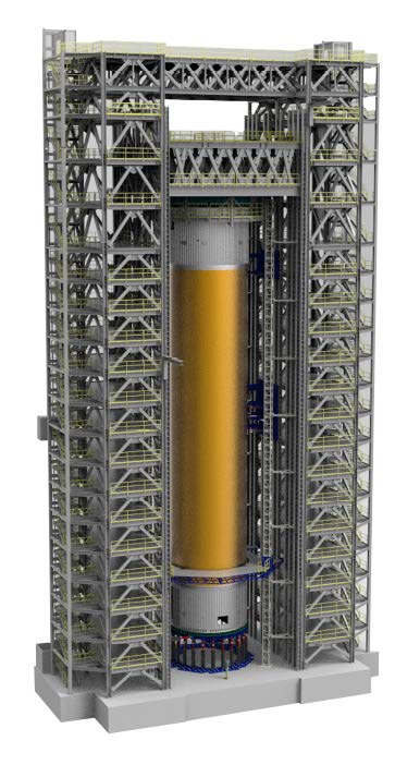
The liquid hydrogen tank test article, which includes the tank, is 149 feet tall and 28 feet in diameter. It will undergo trials in Test Stand 4693, which features twin steel towers with a crosshead between them that can be lowered to accommodate different configurations and future test needs.
Test Stand 4693
- 115 feet wide (35 meters)
- Two 48 by 20 by 221 foot towers (15 by 6 by 67 meters)
- 48 by 48 foot (15 by 15 meters) concrete reaction floor with 924 anchors on 18 inch by 18 inch grid pattern between towers to accommodate test articles
- Crosshead between towers can be raised and lowered
- 160-ton hoist on crosshead lifts test articles or equipment
- More than 3,560 tons of steel superstructure
- 17-foot-thick foundation contains 835 tons of steel embedded in 3,000 cubic yards of concrete – enough to fill 30 swimming pools
- Built atop foundation of stand used to test Saturn V moon rocket’s F-1 engines in 1960s
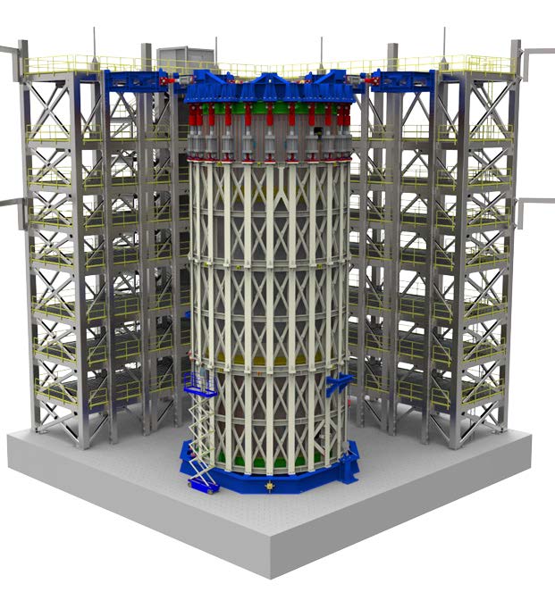
The core stage’s liquid oxygen tank test article is 70 feet tall and 28 feet in diameter. It will be bolted to a massive 185,000-pound steel reaction ring on the foundation of Test Stand 4697. The stand’s wide “L” configuration will accommodate the SLS tank and future testing of a variety of tank or component diameters and configurations.
Test Stand 4697
- 97 foot tall “L” shaped stand (30 meters)
- 91 foot (28 meters) and 80 foot (24 meters) long sections, each 20 feet (6 meters) wide, form arms of “L”
- 60 by 60 foot (18 by 18 meters) concrete reaction floor with 924 anchors on 18 inch by 18 inch grid pattern between arms to accommodate test articles
- More than 1,580 tons of steel superstructure
- 7.5-foot-thick foundation (2 meters) contains approximately 641 tons of steel embedded in 2,200 cubic yards of concrete
When a tank structural test article is positioned in a stand, engineers will connect the special test equipment that simulates launch and flight forces and environments, while measuring and recording the effects — a complex process that can take up to six months. For example, for the liquid hydrogen tank at Test Stand 4693, 38 hydraulic cylinders or “loadlines,” each weighing from 500 to 3,200 pounds (approximately 227 to 1,451 kilograms), are calibrated and then positioned at points all along the tank to apply millions of pounds of pulling and crushing force, and up to 340,000 pounds (approximately 154,221 kilograms) of shearing or sideways force. Tanks are also filled with cryogenic fluids to simulate fuel and propellants used during flight. Specialized instrumentation is precisely attached to capture more than 3,500 strain and deflection measurements, temperatures, pressures, high-definition imaging and other information.
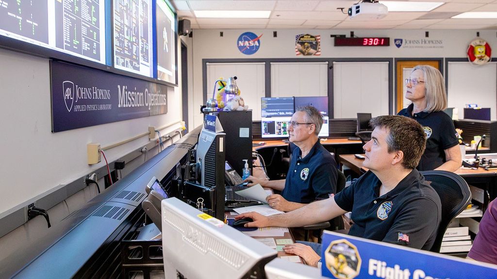
When testing is underway, it will take up to four months to complete each tank’s series of about 30 test scenarios involving varying tank pressures, temperatures and combinations of loads and stresses to simulate different phases of a launch and flight. Test engineers, stress analysts and designers can safely monitor testing and data streaming from both stands over miles of fiber optics cables to a control room in Marshall’s East Test Area.
Test Stands 4693 and 4697 were designed and developed by Marshall’s Test Laboratory and the Office of Center Operations. The U.S. Army Corps of Engineers provides oversight for the construction contract for the government. Construction partners include general contractor Brasfield & Gorrie of Birmingham, Alabama; architects Goodwin Mills and Cawood of Montgomery, Alabama; architects Merrick & Company of Greenwood Village, Colorado; steel fabricators North Alabama Fabricating Co. of Birmingham; and steel erectors LPR Construction of Loveland, Colorado.