


When cooking on a grill, one may notice that certain areas of the grate burn hotter than others. A similar phenomenon affects test stand flame deflectors at NASA’s Stennis Space Center, albeit involving considerably hotter rocket engine exhaust.
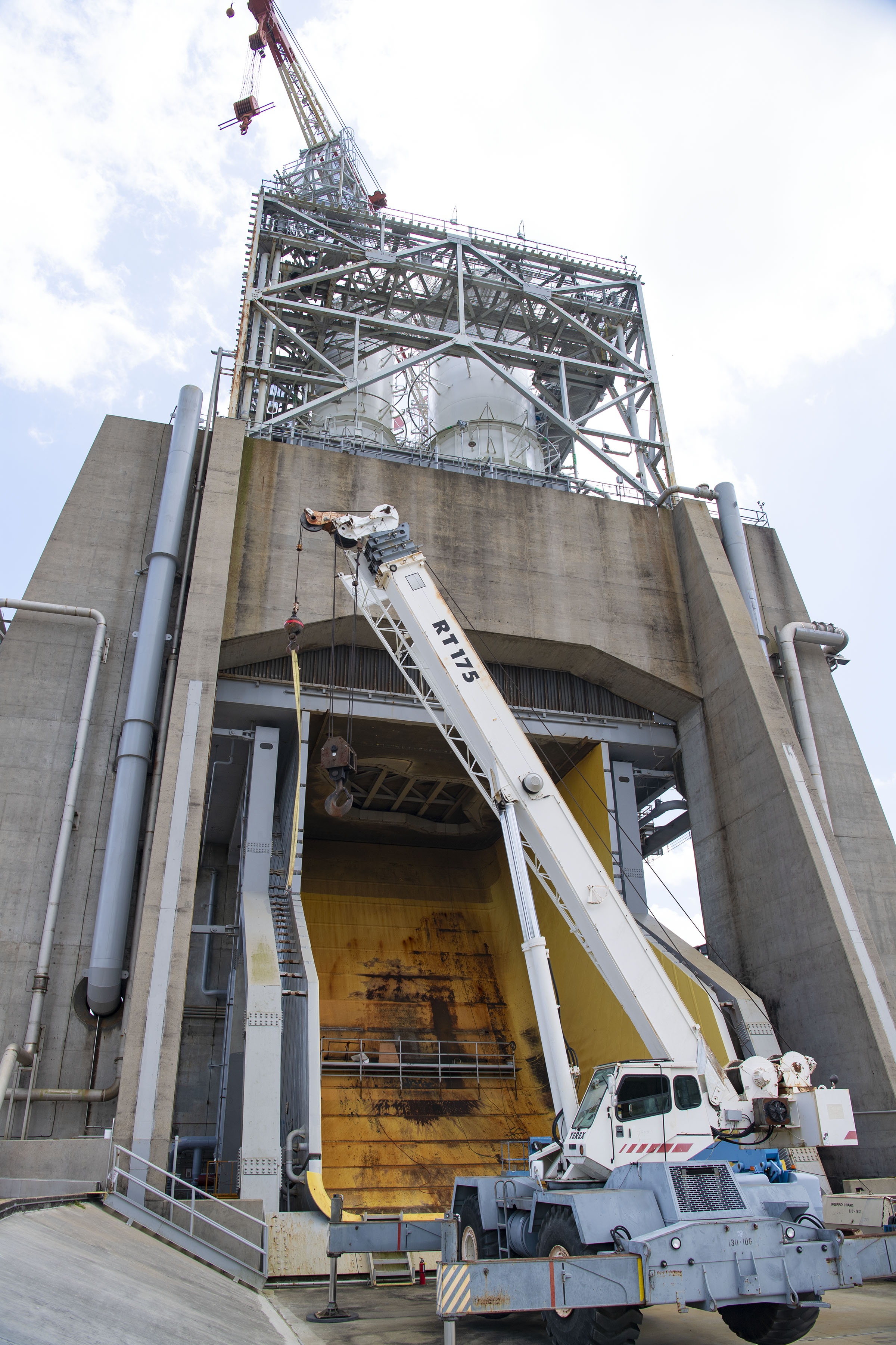
Ensuring the flame deflectors can withstand the ultra-hot temperatures requires careful and precise work. Even now, Stennis teams are engaged in a critical – and intricate – maintenance project to protect the flame deflector on the Fred Haise Test Stand, where RS-25 engines for NASA’s Space Launch System (SLS) rocket are tested.
“People would be surprised at what goes into maintaining our test infrastructure,” said Jared Grover, the NASA manager leading the Fred Haise Test Stand project. “The test stands and facilities are massive and durable, but there is a level of detailed and even delicate work needed to ensure they function as needed.”
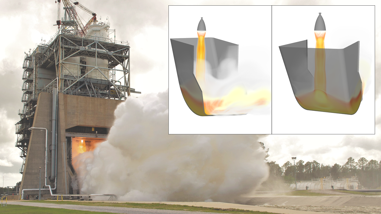
During testing on the Fred Haise stand, for instance, an RS-25 engine’s combustion chamber reaches 6,000 degrees Fahrenheit. Its exhaust plume hits the test stand’s J-shaped flame deflector at temperatures around 5,000 degrees Fahrenheit and sends a cascade of shockwaves throughout the structure.
The exhaust is cooled by high-pressure water sprayed into the test stand flame deflector through thousands of 5/32-inch holes. Without the 170,000 gallons of water pumped every minute from the nearby High Pressure Industrial Water Facility, the carbon-steel flame deflector would melt under the superhot exhaust plume.
However, just as with a backyard barbecue grill, the exhaust hits some parts of the flame deflector more directly – and with more heat – than others. To offset the effect, the pattern of holes must be precise and uniquely tailored for a particular test project.
To prolong the life of the test stand and reduce ongoing maintenance costs, crews are now in the process of performing critical modifications on the Fred Haise Test Stand flame deflector. A key part of the work is drilling a new, highly specialized hole pattern to improve water cooling and protect the infrastructure. The hole pattern will be uniquely tailored for the RS-25 testing program.
“An engine plume is essentially a supersonic blowtorch,” Stennis engineer Danny Allgood said. “There are extreme forces at play, such as high temperature and pressure, that are factored in to where we need to drill additional water-cooling holes. The objective is to ensure a layer of water constantly flows over the deflector during testing.”
Allgood serves as NASA’s computational fluid dynamics subject matter expert at Stennis. For the Fred Haise Test Stand project, he led in mapping out the flame deflector’s hottest region, known as the “impingement zone,” where the plume directly impinges on the deflector.
Having tested rocket engines and stages dating back to the Apollo missions, the Fred Haise Test Stand has a proven history of bearing the same temperatures and forces produced by a rocket engine during launch. However, testing RS-25 engines for SLS use – in upcoming Artemis missions to the Moon and eventual flights to Mars – has presented a new set of challenges. The engines sit at a lower point in the test stand (closer to the flame deflector) and operate at higher power levels than engines from some previous test programs.
Moreover, RS-25 engine testing entails “gimbaling,” which refers to re-directing the aim of the engine’s plume around a tight circular axis, a key function for “steering” a rocket by controlling its trajectory in flight.
Allgood conducted computational analysis of several previous RS-25 gimbal tests to track and measure how gimbaling affects the impingement zone. His analysis accurately determined where there is an increased need for additional water-cooling holes.
“Imagine a flashlight, signifying an RS-25 engine, shining down on a flat sheet of paper, producing a circular halo of light,” Allgood said, explaining the analysis process. “Now, imagine tilting that sheet of paper like a ramp, sort of like the shape of the flame deflector. That halo of light – the engine plume – will now look more like an ellipse, or egg, longer than it is wide. With engine gimbaling, the reach of the engine plume’s ‘ellipse’ is even wider and longer, and that represents the area on the flame deflector in need of more water cooling.”
In the center of the ellipse, or zone of impingement, a team of machinists will drill additional holes at an angle of about 60 degrees – slightly off-vertical – in a grid-like pattern, reaching a density of 72 holes per square foot. Some existing holes in this area may be plugged if they do not conform to the planned pattern.
In the remainder of the egg-shaped zone of impingement, more holes (at the same angle of about 60 degrees) will be drilled to a density of 20 holes per square feet, since the exhaust plume from a gimbaling engine will only briefly be directed at this area. The hole angling is intended to help water flow more easily down the flame deflector and insulate the surface from the engine plume as much as possible.
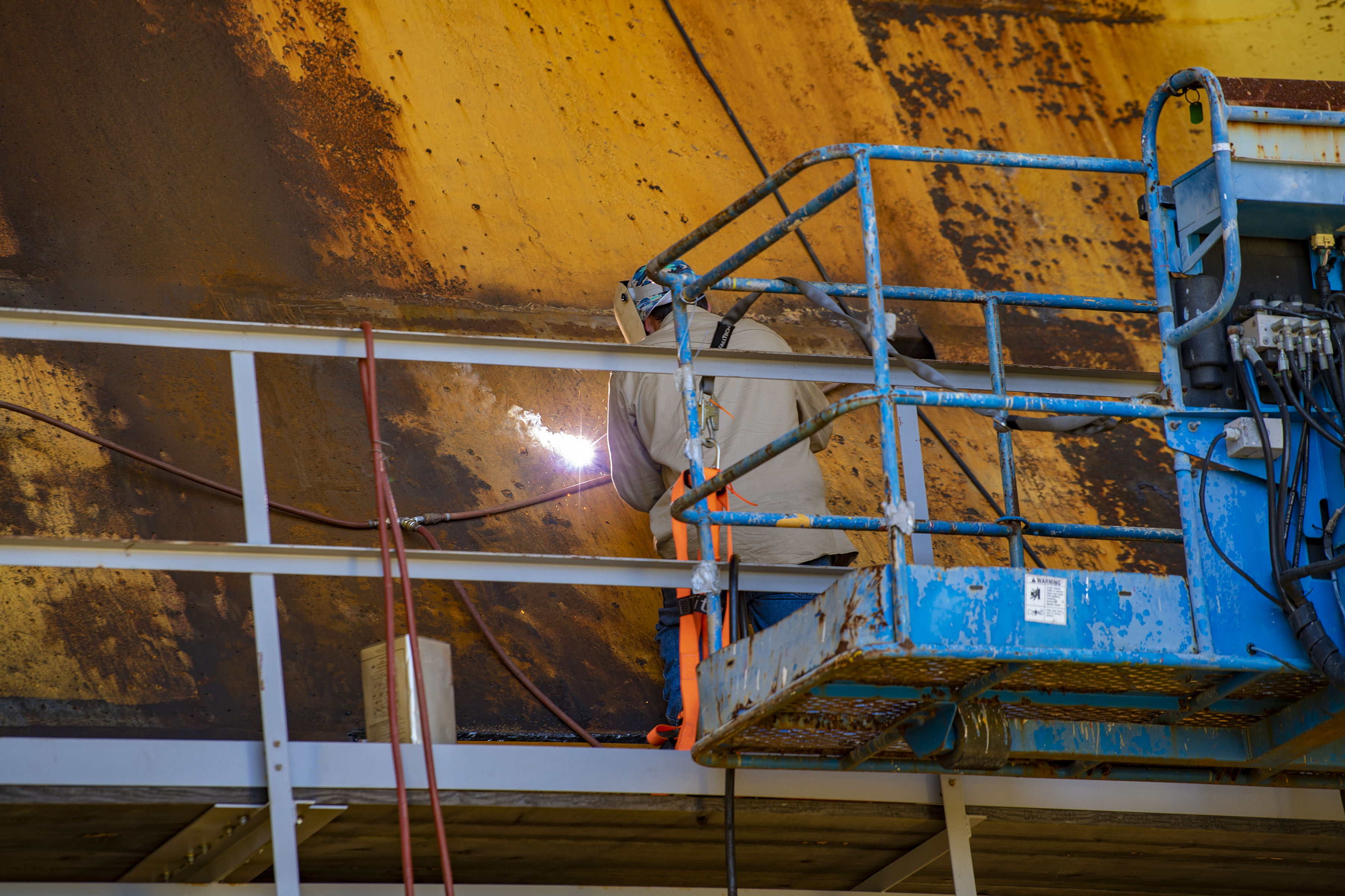
In addition to the spray pattern effort, weld crews also are completing work on the flame deflector manifold structure. The flame deflector consists of 21 horizontal manifolds, or “water boxes,” similar to the non-overlapping bands of armor on an armadillo. Each one is about one foot deep, five feet high, and 44 feet wide, from bend to bend. Stacked together to make up the flame deflector, they tower 83 feet high.
The structure also includes some “mini wet manifolds” that spray additional water in high-heat areas. The current project involves installing more mini manifolds in the hottest area of the flame deflector to improve cooling performance.
“Welders and machinists have always been an integral part of performing the maintenance and modifications we need to test the future of spaceflight,” Grover said. “From the engineers and analysts who draw up our work plans to the welders and machinists who follow them with precision, our team is ensuring that Stennis Space Center remains America’s premier rocket propulsion test site for decades to come.”
For information about Stennis Space Center, visit:
C. Lacy Thompson
Stennis Space Center, Bay St. Louis, Miss.
228-363-5499
calvin.l.thompson@nasa.gov