


![Request for Information – Potential [Placeholder for Prize]](https://assets.science.nasa.gov/dynamicimage/assets/science/psd/solar/2023/09/s/solarsystem_0.jpg?w=1024)


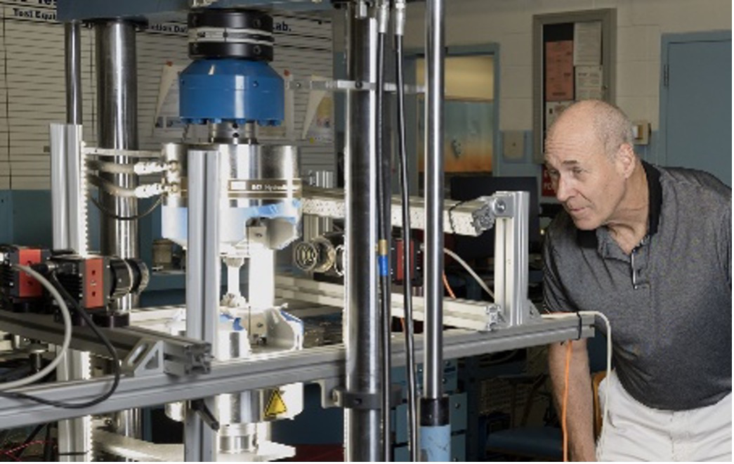
The Structures Technical Discipline Team (TDT) was involved in numerous investigations this past year, but composites, fracture mechanics, and pressure vessels dominate the list. All three of these specialties are important to composite overwrapped pressure vessels (COPV). One of the TDT’s most important findings this year was the exposure of an inherent vulnerability that underpredicts structural life, driven by current specifications and testing standards for COPVs. This NESC work and its recommendations will significantly improve safety and mission success for all current and future COPV operations throughout the aerospace community.
Damage Tolerance Analysis Standard Can Be Unconservative for COPVs
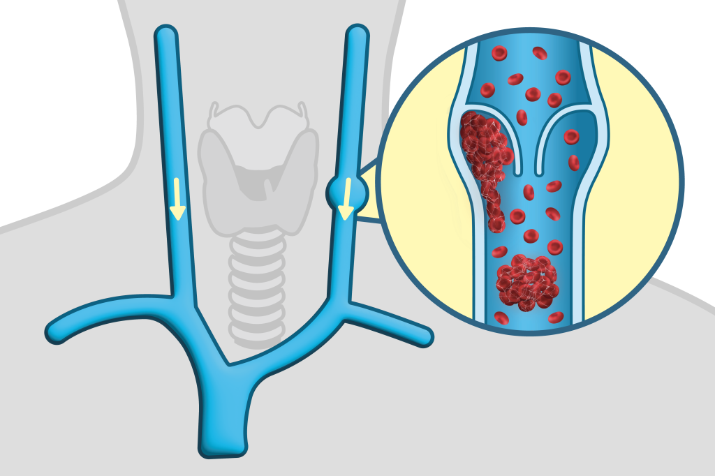
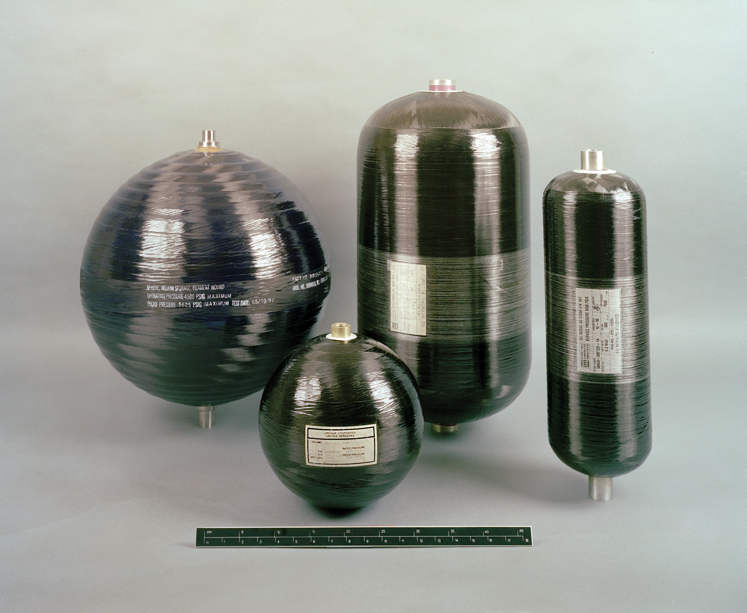
COPVs consist of a metallic liner that contains the fluid or gas and a composite overwrap that provides strength (Figure 1). The operational pressure cycles for a spaceflight COPV generally starts with an initial overpressure, called an autofrettage cycle, that yields the metallic liner, while the stronger composite overwrap remains elastic. Liner yielding during autofrettage results in a small amount of liner growth, resulting in liner compression when the COPV is depressurized after autofrettage. The subsequent operational cycles can be either elastic (elastically responding COPV) or elastic-plastic (plastically responding COPV).
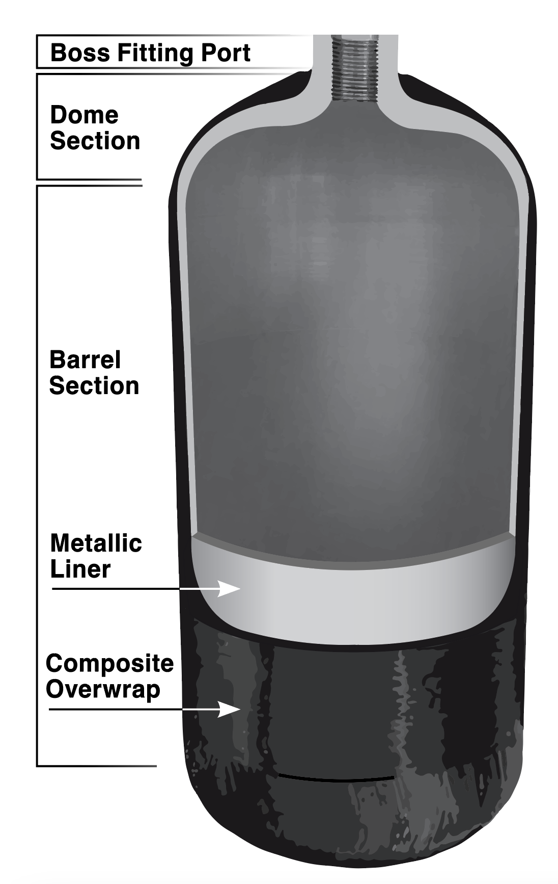 Figure 1.Illustration of COPV major components.
The damage tolerance life evaluation of spaceflight COPVs is governed by the ANSI/AIAA-S-081B, Space Systems–Composite Overwrapped Pressure Vessels. This standard provides the baseline requirements for damage tolerance analyses (DTA) of COPVs with elastically responding liners. The standard allows the DTA to consider the influence of the elastic-plastic autofrettage cycle independently of the elastically responding cycles. The elastically responding cycles are permitted to be analyzed using linear elastic fracture mechanics (LEFM) tools like the NASGRO crack-growth analysis software. The standard states that the DTA must not consider any beneficial influences of the autofrettage cycle on the subsequent elastically responding cycles but does not consider the possibility of detrimental influences of the autofrettage cycle.
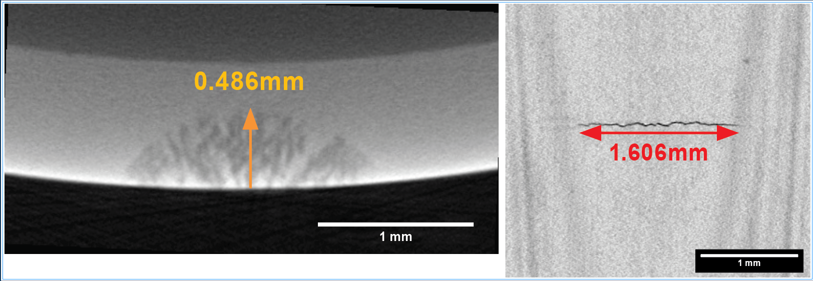
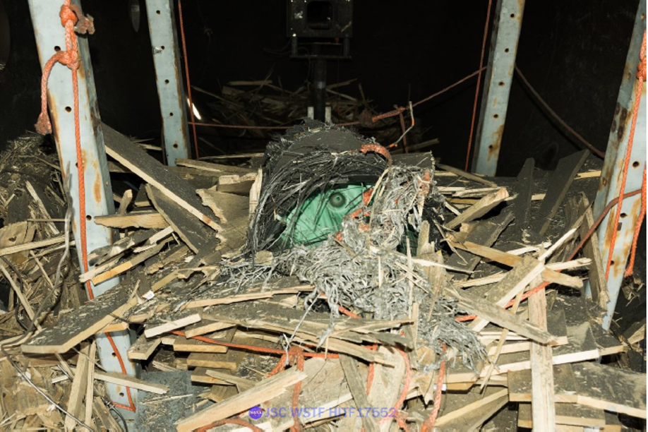
In the study, Unconservatism of Linear-Elastic Fracture Mechanics Analysis Post Autofrettage (NASA/TM-20230013348), an NESC team conducted a combined experimental and analytical investigation into the influence of the autofrettage cycle on subsequent elastic cycles. Tests were conducted on coupons with part-through surface cracks that were subjected to cyclic loading that was representative of the operational cycles of a COPV liner. Half of the tests were conducted with the full loading history (including the autofrettage cycle) and the other half were identical except that the autofrettage cycle was omitted. Cracks in the tests with the autofrettage cycle grew faster than cracks in the identical tests that excluded the autofrettage cycle, as shown by the fracture surfaces in the photomicrographs (Figure 2). The distance between the mark left by the autofrettage cycle and the ductile fracture region was the amount of crack growth (Δa=0.0077 inch) due to the LEFM cycles. Crack growth due to the LEFM cycles in the LEFM-only test was Δa=0.0022 inch, more than three times slower than that in the identical autofrettage plus LEFM test.
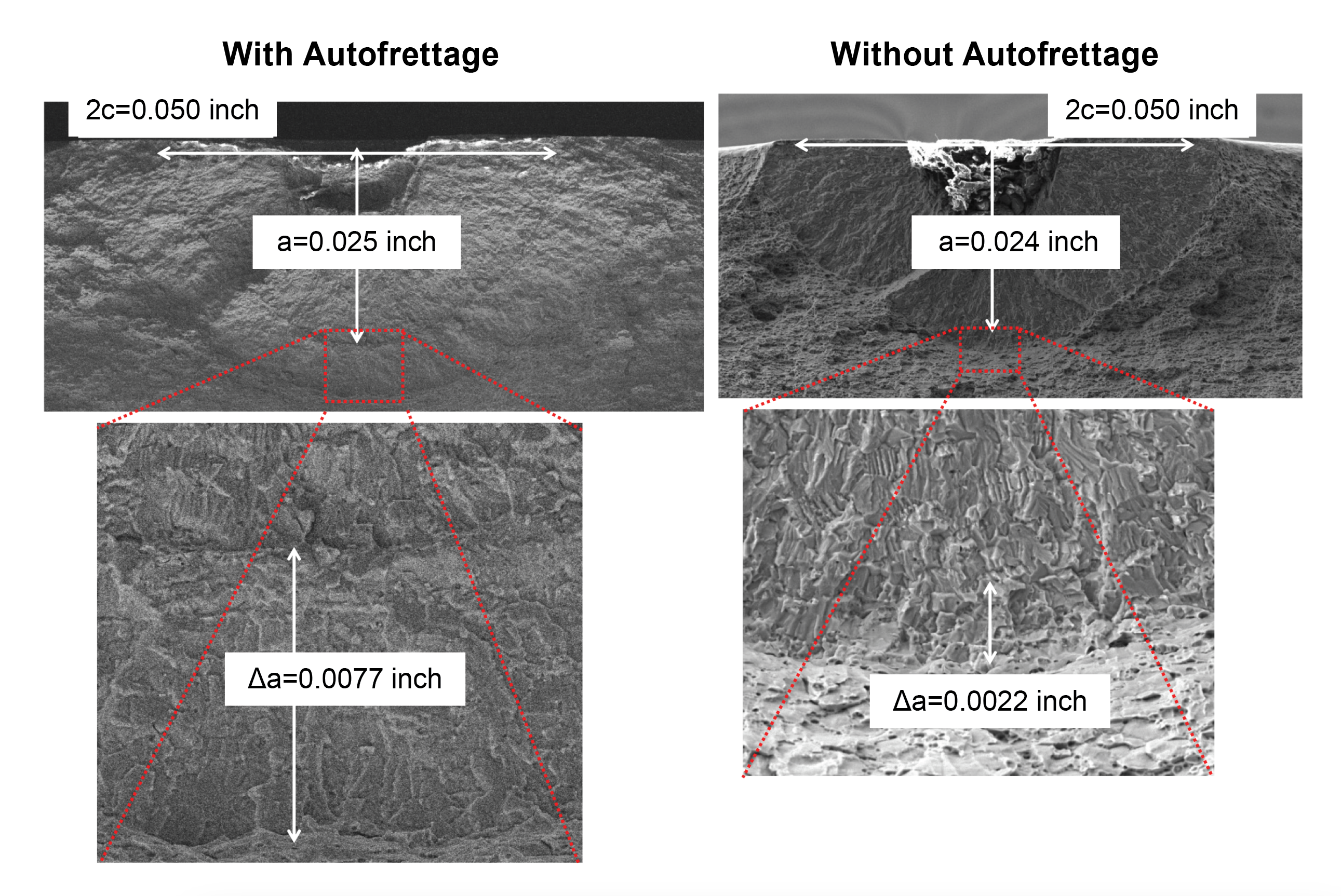
Figure 2. Fracture surfaces from two identical tests showing crack growth (Δa), with and without an initial autofrettage cycle.
A validated finite element analysis and experimental measurements were used to evaluate the influence of the autofrettage cycle. The elastic-plastic autofrettage cycle was found to create a large region of plastic deformation ahead of the crack and blunted the crack tip. Previous fracture mechanics tests and analytical studies in the literature examined elastic overloads and found that plastic deformation ahead of the crack developed residual stresses that closed the crack surfaces, reducing the subsequent crack growth rate. However, the crack blunting allowed the crack to remain open for the entire loading, as illustrated by the finite element simulations of the crack surfaces at peak and minimum stress (Figure 3). The differences between the tests with and without the autofrettage cycle that were observed experimentally and simulated with a validated finite element analysis indicate that the damage tolerance analysis approach allowed by the standard can be unconservative. The NESC proposed an alternative damage tolerance analysis approach and recommended that the AIAA Aerospace Pressure Vessel Committee on standards update the ANSI/AIAA S-081B standard to address COPV liners with compressive stresses following the peak autofrettage stress.
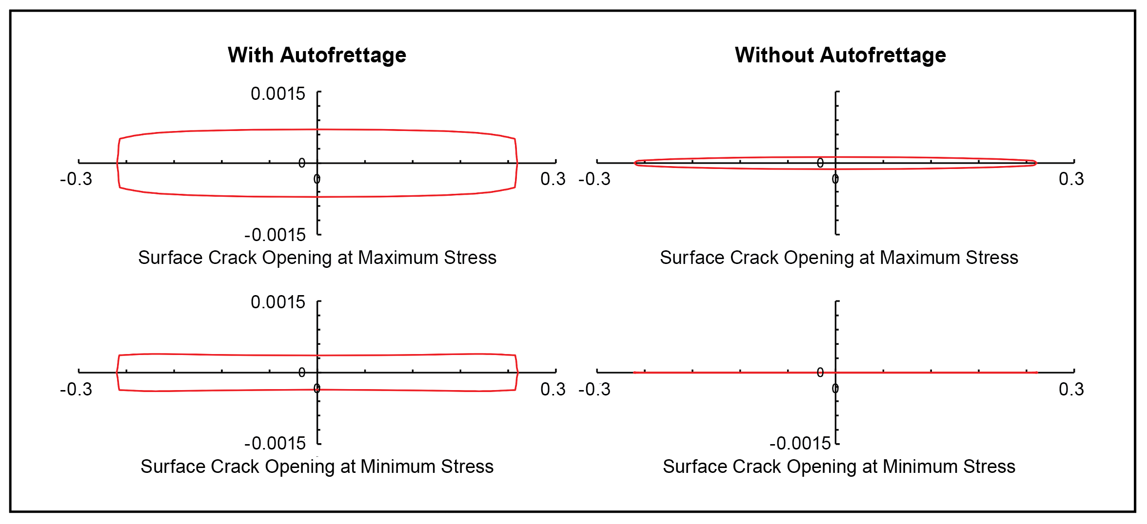
Figure 3. Abaqus finite element analysis of crack growth with and without an autofrettage cycle. Y-axis indicates crack opening displacement and x-axis indicates crack length.
A Brief Introduction to Damage Tolerance for COPVs
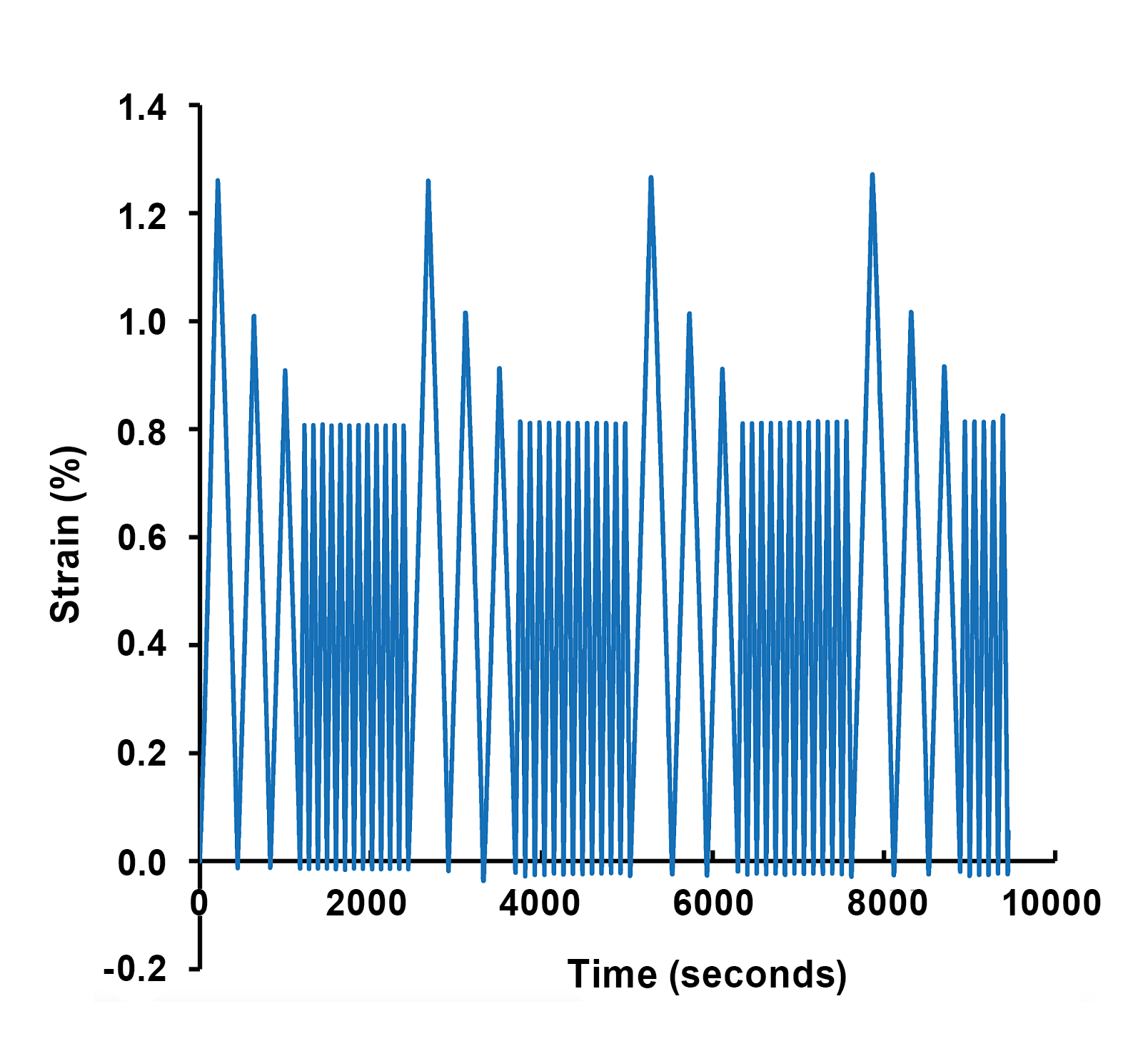
ANSI/AIAA S-081B standard, Space Systems–Composite Overwrapped Pressure Vessels, is a compilation of accepted practices for COPVs used in space applications developed as a collaboration of industry, government, and universities. The standard covers many aspects of COPVs including damage tolerance life analyses that are used for flight qualification overseen by fracture control boards. The standard for damage tolerance requires that the COPV “…survive four operational lifetimes with the largest crack in the metallic liner that can be missed by a nondestructive evaluation (NDE) subjected to bounding stresses representative of what the COPV experiences in its life (manufacturing, integration, operational including thermal and residual).” The operational life of a COPV liner typically includes an initial elastic-plastic cycle (autofrettage or proof) followed by other cycles that may be elastic (elastically responding liners) or elastic-plastic (plastically responding liners). A representative load spectrum is shown at right. During autofrettage, the COPV is pressurized to at least proof pressure to compress the liner inner surface, making it less susceptible to operational stresses. COPVs with elastically responding liners may be damage-tolerance qualified using LEFM analysis tools, but plastically responding liners must be damage-tolerance qualified by testing. Guidance on evaluating the appropriateness of LEFM tools for COPV damage tolerance was provided in NESC Technical Bulletin No. 21-04, Evaluating Appropriateness of LEFM Tools for COPV and Metal Pressure Vessel Damage Tolerance Life Verification Tolerance Life Verification and NASA/TM-2020-5006765/Volumes 1/2.
Future of the Structures Discipline
As the Agency moves more toward forming strategic industry partnerships with commercial contracts for new programs, the Structures TDT has highlighted the need for proper focus on appropriate requirements as the Team’s strategic vector. Although NASA Standards are often provided for reference, their prescriptive nature is not necessarily appropriate for use with commercial contracts. Industry partners and/or NASA team members create alternative standards, unique for each program, but there is inconsistency across different programs with respect to detailed requirements in these standards. Emerging technologies such as soft goods, large-scale deployable structures, inflatables, probabilistic analysis techniques, and additive manufactured hardware all drive unique requirements. The TDT identified the need for a tailoring guide, tied to mission priorities and risk postures, to assist with insight/oversight strategies for NASA programs. Using industry partners also means less NASA-owned hardware, which can lead to a loss of institutional knowledge.
Its imperative that Engineering Directorates at each center proactively look for in-house projects so the next generation of engineers have opportunities for hands-on experience developing, designing, and testing (DDT) flight hardware. This experience is the foundation necessary for NASA engineers to guide the commercial partners through their own DDT processes and to be able to provide appropriate verification and validation of NASA requirements. Structures TDT members form a diverse team crossing all centers and programs, facilitating good collaboration on requirement interpretation, which ultimately ensures safety of NASA crew and mission success of operations in these new commercial programs.