


In This Week’s Star
- Space Launch System Program Moves Forward with Critical Design Review
- NASA Test Materials to Fly on Air Space Plane
- Software Developed by SERVIR Interns Aids Nepal Earthquake Response
- Getting the LDSD Vehicle to Test Altitude
- MARS Team Redstone Alliance for Cycling Hosts 14th Annual Directors Tour d’Arsenal May 19
- Marshall Star Receives Mobile-Friendly Facelift
Space Launch System Program Moves Forward with Critical Design Review
By Megan Davidson
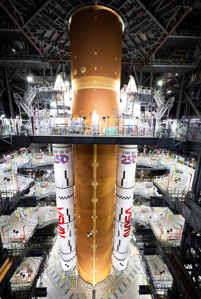
NASA’s Space Launch System Program kicked off its critical design review May 11 at NASA’s Marshall Space Flight Center.
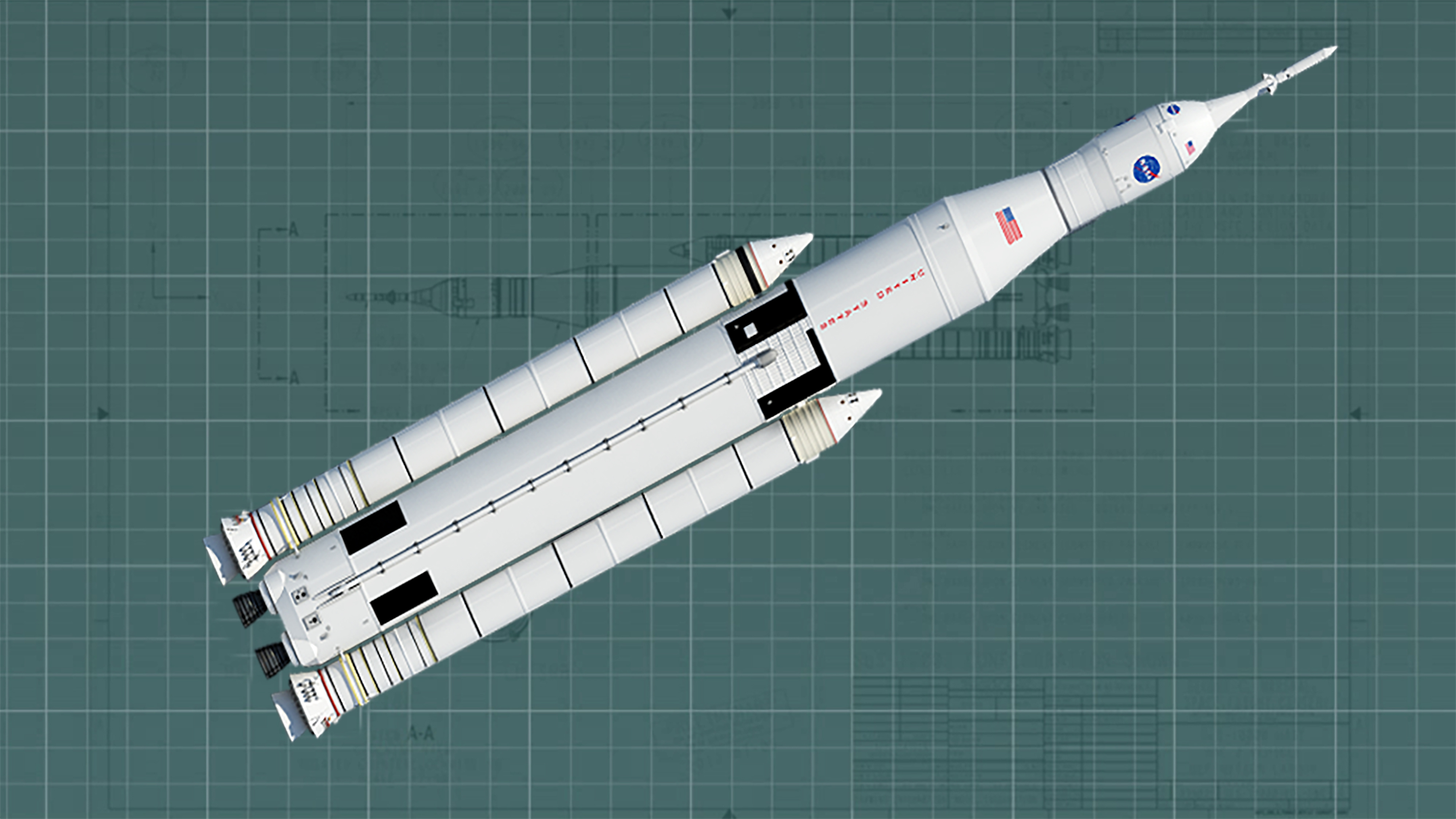
This new rocket will be the most powerful launch vehicle ever built. It is designed to be sustainable and evolve to carry crew and cargo on deep space missions, including an asteroid and ultimately to Mars.
Milestone reviews like the critical design review are just that — critical. The critical design review demonstrates that the SLS design meets all system requirements with acceptable risk, and accomplishes that within cost and schedule constraints. It also proves that the rocket should continue with full-scale production, assembly, integration, and testing, and that the program is ready to begin the next major review covering design certification.
“We’ve never said building a rocket is easy,” said SLS Program Manager Todd May. “We pore over every part of this rocket during these reviews. Thousands of documents and months of time are put into making sure the design is sound, safe and sustainable, and will make NASA’s mission of furthering human spaceflight possible. We are making advances every day on this vehicle.”
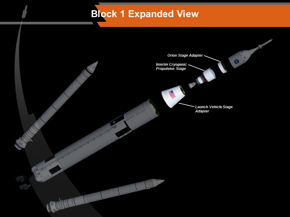
Each element for the rocket — including boosters, engines, stages and Spacecraft and Payload Integration & Evolution — undergo their own reviews before this week’s kickoff of the integrated program review. Boosters, stages and engines have passed their critical design reviews, and the SPIE Office is in the process of completing its critical design review. SPIE is responsible for the design and development of several parts of the top of the rocket, including:
- Orion stage adapter – connects the Orion spacecraft to the SLS
- Orion stage adapter – connects the Orion spacecraft to the SLS
- Interim cryogenic propulsion stage — gives the Orion spacecraft the big push needed to fly beyond the moon before the spacecraft returns to Earth during the first flight test of SLS
- Launch vehicle stage adapter — used to connect the core stage and interim cryogenic propulsion stages
SPIE also works to prepare for the future evolution of SLS to provide the capabilities needed for human missions to Mars. The office oversees in-house research and partners with academia, industry and other government agencies to develop new technologies and systems that will benefit not only SLS, but also the larger U.S. launch industry.
“We look forward to the completion of our critical design review, and continuing the work our talented team does each day in preparing for the first flight of SLS, and missions to come,” said Chris Crumbly, manager of the SPIE Office at Marshall, where the SLS Program is managed for the agency.
The SLS Program critical design review is targeted to conclude in late July.
The first flight test of the SLS will be configured for a 70-metric-ton (77-ton) lift capacity and carry an uncrewed Orion spacecraft beyond low-Earth orbit to test the performance of the integrated system. As the SLS evolves, it will be the most powerful rocket ever built and provide an unprecedented lift capability of 130 metric tons (143 tons) to enable missions even farther into our solar system.
For more information on SLS, click here.
Davidson, an ASRC Federal/Analytical Services employee, supports the Office of Strategic Analysis & Communications.
NASA Test Materials to Fly on Air Force Space Plane
Building on more than a decade of data from International Space Station research, NASA is expanding its materials science research by flying an experiment on the U.S. Air Force X-37B space plane.
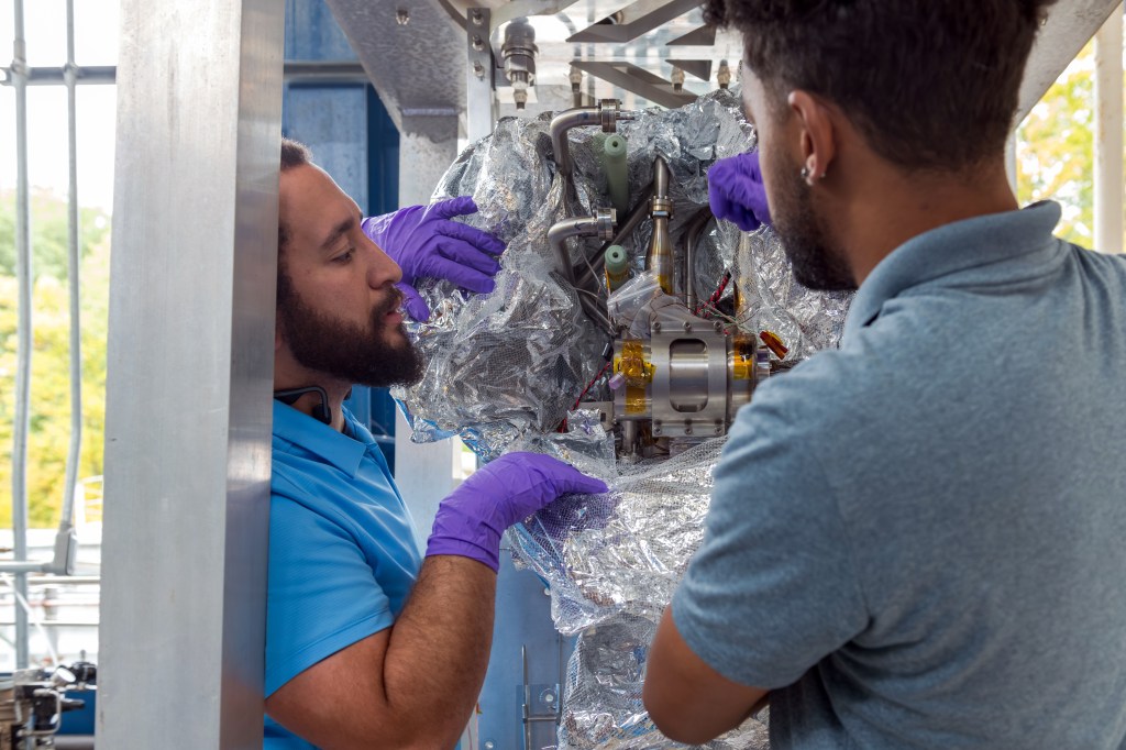
By flying the Materials Exposure and Technology Innovation in Space (METIS) investigation on the X-37B, materials scientists have the opportunity to expose almost 100 different materials samples to the space environment for more than 200 days. METIS is building on data acquired during the Materials on International Space Station Experiment (MISSE), which flew more than 4,000 samples in space from 2001 to 2013.

“By exposing materials to space and returning the samples to Earth, we gain valuable data about how the materials hold up in the environment in which they will have to operate,” said Miria Finckenor, the co-investigator on the MISSE experiment and principal investigator for METIS at NASA’s Marshall Space Flight Center. “Spacecraft designers can use this information to choose the best material for specific applications, such as thermal protection or antennas or any other space hardware.”
The International Space Station is a unique orbiting laboratory used to conduct hundreds of investigations each year, with half of the research resources designated as a U.S. National Laboratory for investigations selected through the Center for the Advancement of Science in Space (CASIS) to provide direct benefits to people living on Earth. NASA research focuses on advancing scientific knowledge and demonstrating technologies to enable human exploration into deep space through investigations such as the current one-year mission with NASA astronaut Scott Kelly.
It is difficult to simulate all the aspects of the space environment, so testing materials for extended durations is particularly important. Programs across the aerospace industry, including NASA’s Mars Curiosity rover, the James Webb Space Telescope, and SpaceX’s Dragon spacecraft have improved performance by selecting materials tested on the space station. All of the data from the MISSE investigations are available in the Materials and Processes Technical Information System, where the METIS data also will be made available.
Researchers are flying some materials as part of METIS that also were tested during MISSE. Testing the same types of materials again can help scientists verify results obtained on the orbital outpost. If researchers see different results between the same type of materials used on both METIS and MISSE, it would help scientists learn about the differences experienced in various orbital environments.
“When we flew newly developed static-dissipative coatings on MISSE-2, we did not know they would be used for both the Curiosity rover and the SpaceX Dragon,” said Finckenor. “Some program we don’t know about now will be successful because engineers found the data they needed.”
The METIS experiment complements the station research, looking at a variety of materials of interest for use on spacecraft built by NASA, industry, and other government agencies. The materials flown in space are potential candidates to replace obselete materials with environmentally-friendly options.
Finckenor leads a diverse team of investigators from other NASA centers, aerospace companies, and universities. For both MISSE and METIS, the customers supply small quarter-size samples. METIS will fly a variety of materials including polymers, composites, and coatings. Finckenor prepares the samples for flight and helps with post-flight sample analysis.
“Data from the space station and METIS materials experiments will improve the lifetime and operations of future spacecraft needed for NASA’s journey to Mars,” said Lisa Watson-Morgan, Marshall’s chief engineer.
Marshall provided the hardware for the experiment, while the Air Force is providing NASA the opportunity to fly the experiment. The flight provides researchers an opportunity to collect additional data in advance of the next MISSE experiment aboard the space station in a couple of years.
The Air Force operates the unpiloted, robotically controlled and reusable X-37B space plane to test technology during long-duration missions. It has completed three missions launching from Cape Canaveral Air Force Station in Florida and landing at Vandenberg Air Force Base in California, with the last mission ending in October 2014 after 674 days in orbit. It takes off vertically, lands horizontally, and continues to further industrial advancement for reusable space test vehicles.
Data in the Materials and Processes Technical Information System are available to U.S. citizens, who can apply for an account on the MAPTIS webpage.
More information about the MISSE experiments and data is available here.
Software Developed by SERVIR Interns Aids Nepal Earthquake Response
An innovative software code developed by a pair of interns who worked for SERVIR last summer is proving remarkably useful in support of disaster response in Nepal after the April 25, magnitude 7.8 earthquake and its subsequent aftershocks shook the Gorkha district.
The SERVIR Coordination Office at NASA’s Marshall Space Flight Center is assisting the International Center for Integrated Mountain Development with the Himalaya disaster recovery mapping efforts in Nepal. SERVIR and its partners are identifying quake-affected sites and tasking NASA satellites to image them. They are also selecting commercial high-resolution imagery of the most affected areas to support recovery. However, these high-resolution images are too large to be received on location in Nepal, where bandwidth is currently limited.
A software code developed by summer interns Sajay De La Puente and Xien Thomas makes it possible for the SERVIR team to create a predefined grid to segment the large disaster images into subsets or ‘tiles’ that can be transmitted and received more easily than the large file, and to reconstruct the pieces on the recipient’s side. The software is allowing the recipient — ICIMOD/SERVIR-Himalaya — to receive and print the images and provide them to Nepal government agencies to guide recovery efforts and help those in need.
“Our interns are assigned projects to develop solutions for addressing issues relevant to SERVIR’s overall aim: to help developing countries use information provided by Earth-observing satellites and geospatial technologies to manage climate risks and land use,” said SERVIR Project Director Dan Irwin. “We are so pleased that we can take what they created and use it to help people in a critical real-world situation.”
De La Puente, now a fourth year computer engineering student at Florida International University, and Thomas, studying computer science at Texas Southern, developed the code to enhance SERVIR’s existing Clip, Zip and Ship tool. Clip, Zip and Ship is designed to make it easy for data analysts to get the information they need for making decisions related not only to disaster response but also to environmental issues such as land cover change, ecosystems and more. With the enhancement engineered by the two interns, the user can define an area of interest on a map by outlining it with a drawing tool and automatically download relevant SERVIR datasets for that area — soil, land cover and land use, ecosystems, or any other SERVIR product that has a geospatial element. The datasets are extracted from more than 30 gigabytes of spatial data stored across multiple geospatial databases. A background process extracts the data within the selected area, creates a compressed package and provides links for the files of interest.
This segmenting approach allows the analyst and geographic information systems expert to get information for just the areas they need.
“In the case of the Gorkha earthquake, the information has proven invaluable,” Irwin said.
For more information about SERVIR, visit NASA’s SERVIR page or www.servirglobal.net.
Getting the LDSD Vehicle to Test Altitude
In June, NASA will conduct the second flight of the Low-Density Supersonic Decelerator test vehicle from the U.S. Navy Pacific Missile Range Facility located on the island of Kauai, Hawaii.
The test will begin at an altitude of about 120,000 feet. But what does it take to get a supersonic test vehicle to that altitude? It’s easier said than done.
In addition to finding a way to deliver the test vehicle to the right height, the project also had to find a location and a team to help coordinate the launch range activities.
“To support the LDSD supersonic flights we turned to NASA’s Wallops Flight Facility, which has experience in launching scientific balloons, conducting remote campaigns and a working relationship with the Pacific Missile Range Facility. All of that experience has been vital in conducting these tests efficiently and successfully,” said Mark Adler, LDSD project manager at NASA’s Jet Propulsion Laboratory.
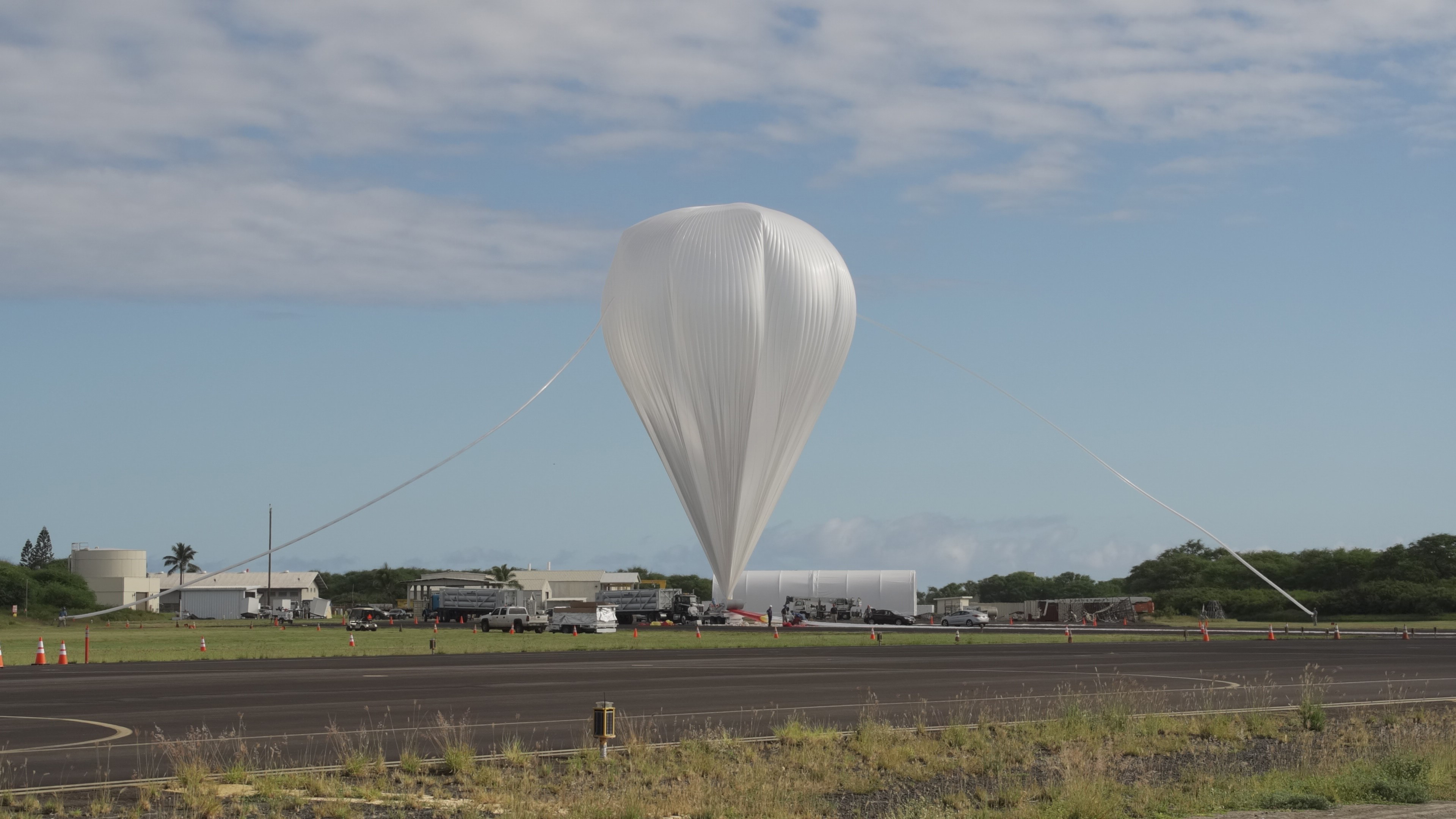
This isn’t your everyday party balloon
NASA balloons are typically used for launching science instruments weighing thousands of pounds to altitudes up to 130,000 feet for durations lasting a few hours to more than a month, from sites all around the world.
The balloon being used for the LDSD test is similar to those used to support scientific flights. The balloon is 34.4 million cubic feet in volume and consists of 22 acres of plastic similar in thickness to that used for sandwich bags. The total flight system length at launch is 980 feet, including the balloon, parachute, cable ladder and test vehicle.
Supported by a team from the Columbia Scientific Balloon Facility in Palestine, Texas, on launch day the balloon is laid out and attached to the test vehicle. Held captive by a large spool, the top section of the balloon is inflated with helium. When the approval is given for launch, the balloon is released by the spool and climbs upward until it is erect overhead of the LDSD test vehicle. The LDSD test vehicle is then released from a first-of-its-kind launch tower and begins its ascent to 120,000 feet. As the balloon rises, the helium expands the balloon so that at peak altitude the balloon would fill a large stadium.
“The largest difficulty in preparing for this mission was developing a system to safely hold and launch the LDSD test vehicle,” said David Gregory, deputy chief of the Balloon Program Office at Wallops.
“Typically, a large mobile vehicle, similar to a crane, holds the science payload and is driven to align the payload under the balloon at launch. However, the LDSD test vehicle contains an Orbital ATK Star-48 solid rocket motor. So, due to safety considerations, a uniquely designed remote-operated static launch tower was built to keep personnel away from the test vehicle at launch,” Gregory said. “This is unlike our typical launches where we use a mobile launch vehicle that requires operations personnel to be in close proximity to the payload at the time of the balloon launch.”
Engineers from Wallops and Columbia Scientific went to work and, with Foremost Industries LP of Calgary, Canada, developed a unique launch tower that safely releases the LDSD test vehicle for its flight to Earth’s upper atmosphere.
“The development of the launch tower was the key to allowing us to successfully and safely launch the LDSD test vehicle,” Gregory said.
Finding the right location
Dave Wilcox, LDSD project manager at Wallops, said, “The other big issue for us was finding a facility with the appropriate wind conditions for the balloon launch and flight and a location that allowed us to provide public and environmentally safe conditions for conducting the LDSD test. After looking at several locations, it was determined that PMRF fit the bill.”
The range facility is providing ground instrumentation for command uplink and flight system (balloon and test vehicle) tracking; the necessary facilities for integration, launch, and operation of the flight system; and the necessary range services such as aircraft surveillance for range clearance.
Wallops has extensive experience in conducting “remote” campaigns through the NASA sounding rocket, balloons and airborne sciences programs. In addition, it is home to NASA’s only owned rocket launch range.
“Because of this experience, Wallops is tasked with the overall mission execution of the project countdown, providing recovery services of the balloon and the LDSD vehicle from the Pacific Ocean following the test, launch of meteorological rockets following the LDSD test and coordinating the support provided by PMRF,” Wilcox said.
“In addition, Wallops is fabricating and providing the test vehicle’s on-board avionics and associated electronic ground support equipment, which are based heavily on proven sounding rocket systems,” he said.
Recovering the flight articles from the Pacific
NASA plans to recover the balloon, test vehicle, and supersonic parachute.
The recovery boats are locally owned and operated fishing/commercial freight vessels that are contracting with NASA to perform the recovery operations. NASA subject matter experts and trained Navy divers will be aboard for the operations. The recovery vessels are being supplied by the Hawaii Resource Group located on the island of Oahu and the spent balloon is being recycled by Pacific Farm Services on Kauai.
The LDSD testing will be conducted through NASA’s Technology Demonstrations Missions program, based at NASA’s Marshall Space Flight Center, with the technology development work and testing led by NASA’s Jet Propulsion Laboratory. NASA’s Wallops Flight Facility is coordinating support with the Pacific Missile Range Facility and providing the balloon systems.
The LDSD project is one of several crosscutting technologies NASA’s Space Technology Mission Directorate is developing to create the new knowledge and capabilities necessary to enable our future missions to an asteroid, Mars and beyond. The directorate is committed to developing the critical technologies required to enable future exploration missions beyond low-Earth orbit.
While the actual test may only last a few minutes, the road to getting to the test is long and the players involved are many.
MARS Team Redstone Alliance for Cycling Hosts 14th Annual Directors Tour d’Arsenal May 19
The MARS Team Redstone Alliance for Cycling will host the 14th annual Directors Tour d’Arsenal on May 19. The ride will be led by Steve Doering, manager of the Space Launch System Stages Office at NASA’s Marshall Space Flight Center.
Beginning at 5 p.m. at the Activities Building 4316 parking lot, cyclists will take a late-afternoon ride on low-traffic roads at an easy pace through interesting and little-known areas of Redstone Arsenal. The ride follows the historical railroad route around the southern part of the arsenal making a loop along Dodd, Buxton and Patton roads, and featuring a trip through Army Test Area 1 and the NASA Test Area.
Last year marked the largest ever Tour d’Arsenal with nearly 250 riders, making it the largest free bike ride in North Alabama. The ride is mostly flat and approximately 19 miles long with 22-25 mile options. All adult, badged Marshall or Redstone Arsenal personnel and escorted guests are welcome to participate.
All anyone needs to participate is a bicycle, helmet, water bottle and reflective vest per Army regulations. Riders can set their own pace for completing the route. Signs will be placed at intersections reminding riders of turns. A water jug will be placed at the halfway point and restrooms are available at the campground near the Tennessee River. Assistance will be available, if needed, for unforeseen difficulties.
Participants are also invited to a free pizza lunch (donations accepted) and ride pre-registration May 18 at 11 a.m., followed by the alliance’s annual meeting at 12:30 p.m. To RSVP for lunch, contact Scott Stevens at 256-961-1246 or scott.stevens@nasa.gov.
Marshall Star Receives Mobile-Friendly Facelift
On April 20, NASA and NASA’s Marshall Space Flight Center webpages received a facelift — including a new, sleek design. The first Marshall Star to reflect these changes was the May 3 issue. The new features are not just visually appealing, but they are functional as well.
The new look is designed to make the Star more mobile-friendly, allowing Marshall team members to read and share the Star on-the-go using their smart phones and tablets. The most noticeable change in the facelift is the Star’s new home page that previews and easily links to past issues and articles.
Though subtle, each change to the Star is designed to enhance the reading experience. Larger headlines serve as a more recognizable, visually pleasing break between articles. Images are clickable and linked to high-resolution images that can be saved and shared. Links make it easy to share articles and issues on social media including Facebook, Twitter and Google+.
A staple at Marshall since the early days of space exploration, the Star strives to continuously improve with the newest technology to better reach the center’s workforce and keep its readers updated with the latest news and information.