


![Request for Information – Potential [Placeholder for Prize]](https://assets.science.nasa.gov/dynamicimage/assets/science/missions/a-step/FFR_Earth_Background_20251120%20.png?w=1024)


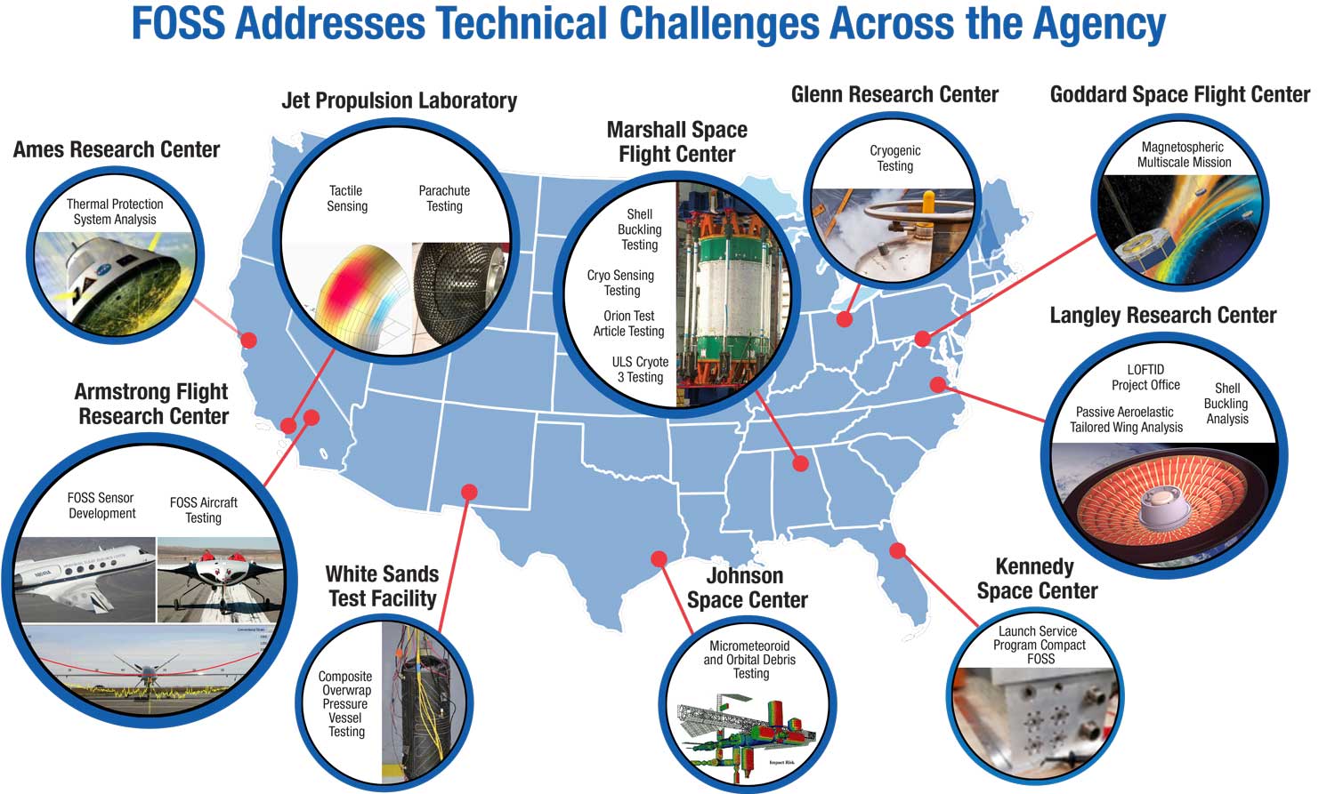
What began as a research tool to collect aerodynamic data from research aircraft is now solving technical challenges within the agency and beyond. NASA’s patented, award-winning Fiber Optic Sensing System (FOSS) technology combines advanced strain sensors and innovative algorithms into a robust package that accurately and cost-effectively monitors a host of critical parameters in real time. It is being widely used throughout NASA to support research projects as varied as investigating next-generation flexible wings, measuring liquid fuel levels, and monitoring strain on spacecraft.
FOSS uses up to a 40-foot, hair-like optical fiber that provides up to 2,000 data points each. The state-of-the-art system processes information every quarter-inch along the fiber at rates up to 100 times per second to measure strain, shape deformation, temperature, liquid level, and operational loads.
Through the years, the FOSS team has optimized the technology to refine the infrastructure and speed with which the system collects and transmits data, and the technology’s easy-to- integrate elements now complement and add color to existing instrumentation.
For example, NASA’s unmanned Ikhana aircraft was the first to fly with a FOSS wing shape sensor. In that test, researchers placed FOSS sensors in the same locations as conventional strain gauges but also ran fibers the length of the wing. While the FOSS sensors matched well with the results from the conventional sensors, they also revealed unexpected high stress points at locations between the conventional sensors—data that would have been completed missed if not for FOSS.
FOSS enables researchers to verify finite element models to a high degree of spatial resolution. It also allows researchers to identify unexpected phenomena in cases where a model is not completely accurate or does not contain enough degrees of specificity. FOSS enables both validation and discovery, making the entire research process more effective and efficient.
Industry has taken notice. Commercial rocket providers are using FOSS in their laboratories, and companies in a variety of industries are exploring how FOSS can improve their operations. The FOSS team continues to refine algorithms to support additional applications, with the goal of adding FOSS to the suite of instrumentation on NASA aircraft, as well as other assets across the agency.
Contacts:
Allen Parker | 661-276-2407 | Allen.R.Parker@nasa.gov
Francisco Peña | 661-276-2622 | Francisco.Pena@nasa.gov
‘Rocket Box’ FOSS
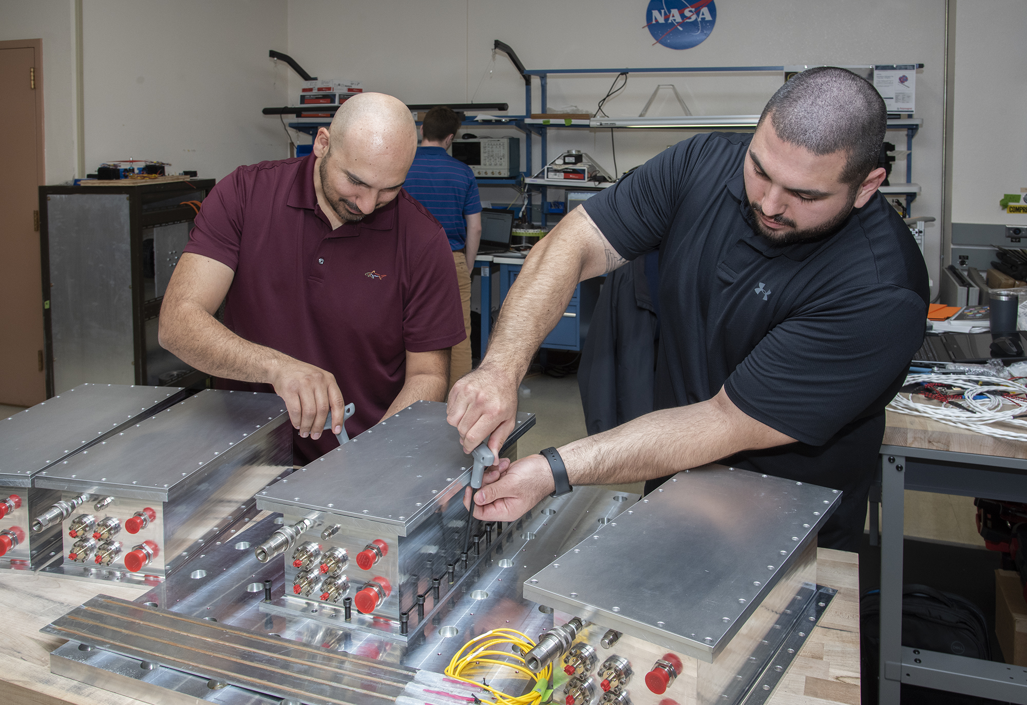
Armstrong and NASA’s Kennedy Space Center researchers have collaborated for years to ruggedize the Fiber Optic Sensing System (FOSS) so it can be used to measure aggressive launch loads on spacecraft. Further collaborations with industry partners have resulted in durable instrumentation, and Armstrong researchers are now readying a new combination of mechanical enclosure and instrumentation for launch within the next year on several rocket launches. The goal is for this “rocket box” to fly on NASA’s Low-Earth Orbit Flight Test of an Inflatable Decelerator (LOFTID) and United Launch Alliance’s Vulcan rocket, as well as with other commercial launch providers.
Work to Date
The FOSS team has assembled five rocket boxes and completed early-stage environmental testing to simulate rocket launch conditions.
Looking Ahead
Next steps are to complete electrical testing in preparation for shipment to NASA’s Langley Research Center for final environmental testing. The goal is to validate that FOSS can provide critical parameter measures (e.g., strain, load, temperature, shape) in aggressive launch environments.
Partners
NASA’s Kennedy Space Center and Langley Research Center and United Launch Alliance
Benefits
- Advanced: Provides validated structural design data that could enable future launch systems to be lighter and more structurally efficient
- Ruggedized: Allows FOSS to be used effectively in many more practical applications that require a more robust system
Applications
- Rockets
- Reentry vehicles
- Jet engines
- Inflatable wings and airships
- Test aircraft
PI: Allen Parker | 661-276-2407 | Allen.R.Parker@nasa.gov
MicroFOSS Technology
Armstrong researchers are reducing the Fiber Optic Sensing System (FOSS) technology’s size, power requirement, weight, and cost to effectively extend opportunities for broader fields of application. Applying lessons learned during development of the “rocket box” technology, they have designed a compact package useful for monitoring a host of critical parameters in real time. Dubbed MicroFOSS, this version of the technology is smaller, less expensive, and more robust. It leverages electronics that are commonly available for the smartphone and tablet industry, departing from the expensive military- grade processors and components of previous versions.
Work to Date
The team developed multiple laboratory systems and successfully tested them in the field. The technology reduces the channel interrogation system from eight channels to between two and four channels. This design simplification minimizes the risk of potential issues during flight, enabling the robustness required for challenging applications.
Looking Ahead
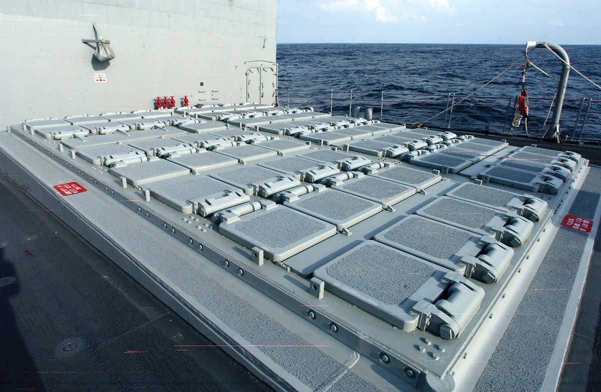
Armstrong is collaborating with the U.S. Navy to provide this technology for integration into naval vessels and expects to deliver the MicroFOSS box in 2020. The team is also evaluating the use of this technology on Armstrong flight vehicles as well as on launch vehicles and satellites.
Benefits
- Compact: Miniaturized size requires less associated hardware than existing systems
- Low cost: Leverages electronics designed for the smartphone and tablet industry
- Reliable: Components are designed for aggressive environments without compromising the form factor
Applications
- Aeronautics and launch vehicles
- Satellites
- Oil drilling, wind energy, and industrial processes
PI: Allen Parker | 661-276-2407 | Allen.R.Parker@nasa.gov
Temperature Sensing
Armstrong researchers have developed a new manufacturing process that improves the ability of fiber optic sensing systems to measure temperature and liquid levels in humid environments. The process involves eliminating moisture from the optical fiber coating, then completing the sensor assembly within humidity-controlled conditions. The resulting sensor hardware provides precise and accurate measurements even when operating in a humid environment. Originally designed to monitor a rocket’s cryogenic fuel levels in conjunction with NASA’s patented FOSS, this technology can be used in many industrial, food, and medical applications.
Work to Date
With funding from NASA’s Center Innovation Fund, Armstrong researchers developed a two-step process to assemble the sensors. First, the bare sensor fiber is inserted into a polymer tube that isolates the fiber yet is still thin enough to provide adequate thermal transfer. Then the tube is purged with gas to expel all moisture from the fiber coating. The innovation was successfully tested at NASA’s Marshall Space Flight Center.
Looking Ahead
The innovation is being patented and has the potential to be licensed outside NASA.
Partner
NASA’s Marshall Space Flight Center
Benefits
- Robust: Provides a moisture-free and mechanically isolated condition for the sensing fibers in cryogenic environments
- Accurate: Offers excellent thermal conductivity to surrounding area, allowing the sensing fibers to determine temperature correctly
- Reliable: Enables fiber optic sensing systems to operate properly in humid conditions
Applications
- Energy: Liquid natural gas and petrochemical storage tanks
- Industrial: Storing cryogenic liquids
- Aerospace: Liquid fuel tanks for launch vehicles
PIs: Allen Parker | 661-276-2407 | Allen.R.Parker@nasa.gov
Shideh Naderi | 661-276-3106 | Shideh.Naderi@nasa.gov
Automated Switching Network
Orbital debris is the number one threat to spacecraft and satellites, as collisions with this debris can cause damage or even catastrophic failures. Armstrong researchers are using NASA’s patented Fiber Optic Sensing System (FOSS) to develop an optical fiber network to monitor the structural health of a spacecraft’s thermal protection system (TPS). FOSS allows engineers to obtain up to 16,000 strain or temperature measurements at quarter-inch increments along eight independent 40-foot sensing fibers.
The new automated network integrates optical switches with FOSS to expand the sensing area by a factor of 24 or greater with limited additional weight and cost for flight applications. The total potential sensor count increases from 16,000 per system to 192,000 sensors to significantly improve performance and reliability of TPS structural health monitoring.
Work to Date
Funding from NASA’s Center Innovation Fund enabled Armstrong researchers to develop a working prototype by integrating the system onto a lab-scale TPS and conducting thermal tests. With this approach, FOSS is time-synchronized with up to 24 optical switches that cycle through sensing fibers periodically until an event is triggered, at which point a switch automatically activates to retrieve dense information about a specific region. The use of peripheral sensors provides feedback to the optical switches to intelligently interrogate sensing fibers of interest temporarily, then resume periodic switching.
Looking Ahead
With funding, researchers will extend testing to a variety of test articles. In addition, the FOSS team is evaluating use of this automated switching technology with the FOSS portfolio.
Benefits
- Detailed: Automatically detects damage at a granular level
- Expands monitoring area: Enables FOSS to cover a much larger surface area
- Connective: Establishes communication between FOSS and optical switches
Applications
- Spacecraft TPS
- Many structural health monitoring applications
PI: Francisco Peña | 661-276-2622 | Francisco.Pena@nasa.gov
Tank Gauging Applications
Armstrong’s Fiber Optic Sensing System (FOSS) technology enables a highly accurate method for measuring liquid levels in challenging situations, such as cryogenic fluids or liquids with stratification that makes gauging challenging. Unlike gauges that rely on discrete measurements to give broad approximations of liquid levels, Armstrong’s CryoFOSS technology provides measurements at quarter-inch intervals within a tank. The system actively discerns between the liquid and gas states along a continuous fiber to pinpoint the liquid level. Originally designed to monitor a rocket’s cryogenic fuel levels, the technology offers numerous benefits for a variety of other industries including oil and gas industry, where users need to determine boundary layers between different fluids and substances, such as oil, water, detergent, sand, and gravel.
Work to Date
This fully developed technology has been demonstrated in multiple environments using conventional validation techniques. During testing at NASA’s Marshall Space Flight Center, the team developed a method to bundle a resistive heater wire with the optical fiber. The heater is pulsed to induce a local temperature change along the fiber, and a fiber Bragg grating monitors the subsequent cooling. Across NASA, FOSS could be used as a tank gauging system for liquid nitrogen environments. Companies are exploring implementation for a use as a gauging system to determine stratification of different substances within a tank.
Benefits
- Increases efficiency: Enables accurate measurement of fluid levels, reducing error margins and excess fuel needs
- Simple design: Requires just one fiber optic strand and one metallic wire
- Robust: Can be used in corrosive or toxic liquids and extreme environments
Applications
- Aerospace liquid nitrogen tanks
- Chemical and refinery plants
- Industrial tanks
PI: Allen Parker | 661-276-2407 | Allen.R.Parker@nasa.gov
X-56A Research
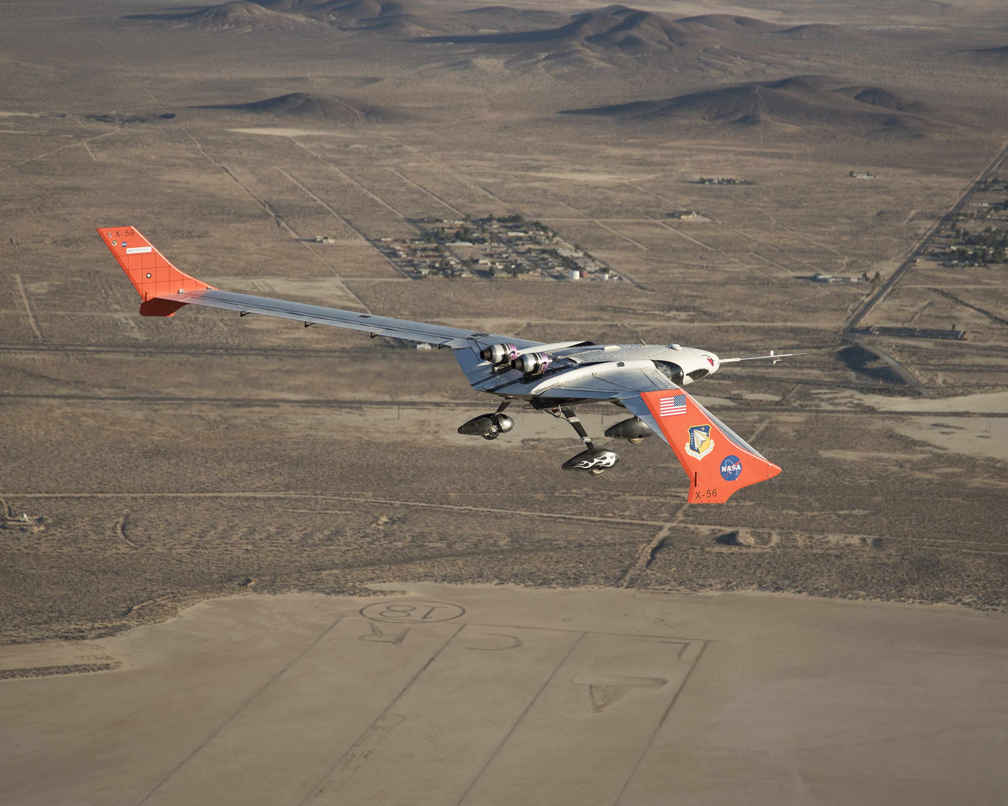
The real-time processing capability of NASA’s Fiber Optic Sensing System (FOSS) makes it an excellent choice to benefit research involving the unmanned X-56A Multi-Utility Technology Testbed (MUTT). The X-56A is a modular, remotely piloted experimental aircraft tasked with investigating flexible wings to improve safety, efficiency, and ride quality. It is being tested using flight profiles where flutter occurs in order to demonstrate that onboard instrumentation can predict, sense, and suppress aeroelastic instabilities. By quickly collecting strain data, FOSS is enabling researchers to see dynamic changes on the wings that could result in flutter.
Work to Date
The FOSS team built a small interrogator specifically for the X-56A and installed optical fibers on the wings. During multiple flight tests, FOSS collected strain and 2D shape data that correlated with models.
Looking Ahead
The team is examining the flight data to determine how to process shape information and feed it back in real time into a flight control computer to dampen or suppress the flutter while in flight. The next set of X-56A flight tests will involve replacing the highly flexible wings with stiffer ones, and FOSS will be part of these flights.
Benefits
- High spatial resolution: Enables measurements approximately every 0.25 inches
- Small and light: Offers 100 times the number of measurements at 1/100 the total sensor weight
Applications
- Aeronautics
PIs: Francisco Peña | 661-276-2622 | Francisco.Pena@nasa.gov
Allen Parker | 661-276-2407 | Allen.R.Parker@nasa.gov
Tactile Sensing
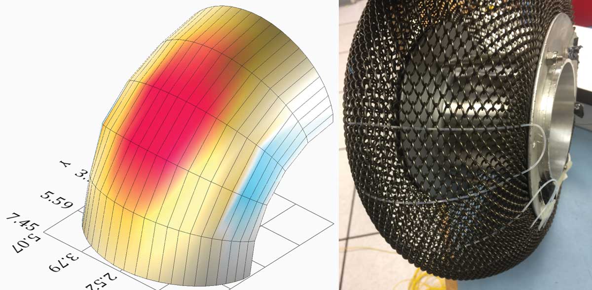
Armstrong researchers are collaborating with engineers at NASA’s Jet Propulsion Laboratory (JPL) to develop and test a sensing system that can provide information about the health of robotic wheels. This research began after JPL scientists observed structural damage in the wheels of the Mars Curiosity Rover due to punctures and metal fatigue. In preparation for future robotic wheels, this project is embedding various test wheels with fiber optic sensors to provide information about the shape of the wheel as it rolls over objects. Armstrong researchers are using NASA’s patented FOSS to monitor and provide detailed information about these structural deformations.
Work to Date
The Armstrong FOSS team instrumented one- third of a mesh wheel with multi-core fiber optic sensors. The sensor line was routed through the wheel at 15° arc intervals. The distributed strain output of each arc was processed individually by a curvature-to-shape algorithm, and the resulting shapes were tied together to form a 3D virtual mesh. An intensity color map was applied to the 3D virtual mesh to distinguish inward and outward deformations as well as magnitude. Researchers determined that the deformation sensing had a good balance between providing insight into the wheel’s external environment and providing information about its internal state.
Looking Ahead
Plans are underway to fully instrument four wheels and integrate them into a rover for testing and demonstration. Potential follow-on research could involve development of a “synthetic skin” embedded with distributed sensors that could be molded to various wheel types.
Partners
NASA’s Jet Propulsion Laboratory and Glenn Research Center
Benefits
- Preventive: Offers the potential to improve robotic rover locomotion and prevent premature structural failure
- Greater capabilities: Provides tactile sensing to mechanical systems
- Responsive: Enables mechanical systems to adapt to unexpected disturbances in an operational environment
Applications
- Rovers
- Aerospace structures
- Deformation studies for terrestrial structures
PI: Francisco Peña | 661-276-2622 | Francisco.Pena@nasa.gov