


![Request for Information – Potential [Placeholder for Prize]](https://assets.science.nasa.gov/dynamicimage/assets/science/missions/a-step/FFR_Earth_Background_20251120%20.png?w=1024)


Increasing efficiency in aerospace vehicles is a key goal across the spectrum of NASA operations. Armstrong researchers are constantly striving to build efficiency into all phases of flight projects, through development, fabrication, and operations processes. From a new wing design that could exponentially increase total aircraft efficiency to novel test techniques that evaluate sensor suites and calibration systems, our researchers are finding unique solutions that increase efficiency.
Armstrong engineers also continue to pioneer new research in aircraft design and modeling. Researchers are experimenting with revolutionary flexible wing technologies that can reduce weight, improve aircraft aerodynamic efficiency, and suppress flutter. The results could enable future airliners to use lighter weight, flexible wing designs to conserve fuel.
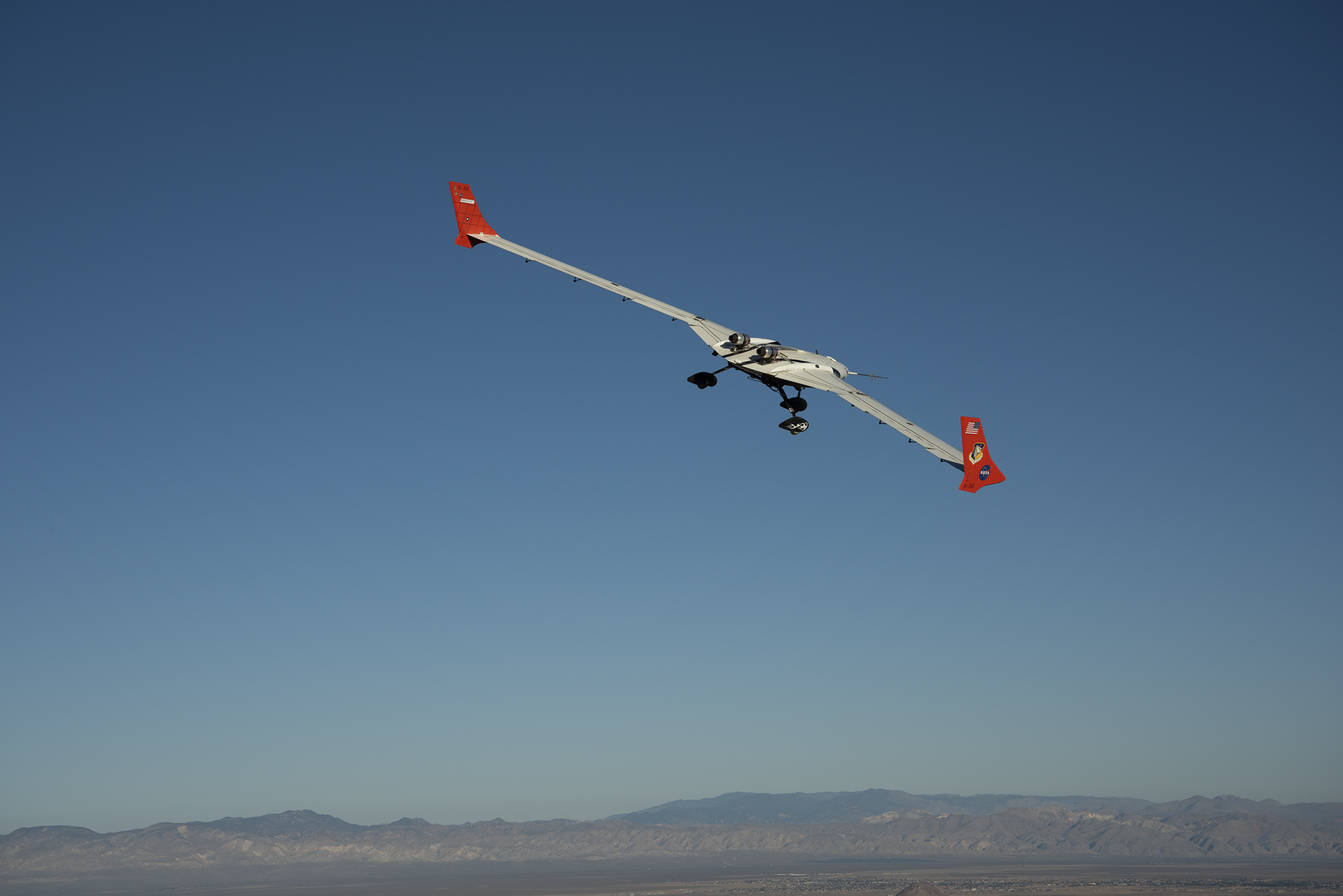
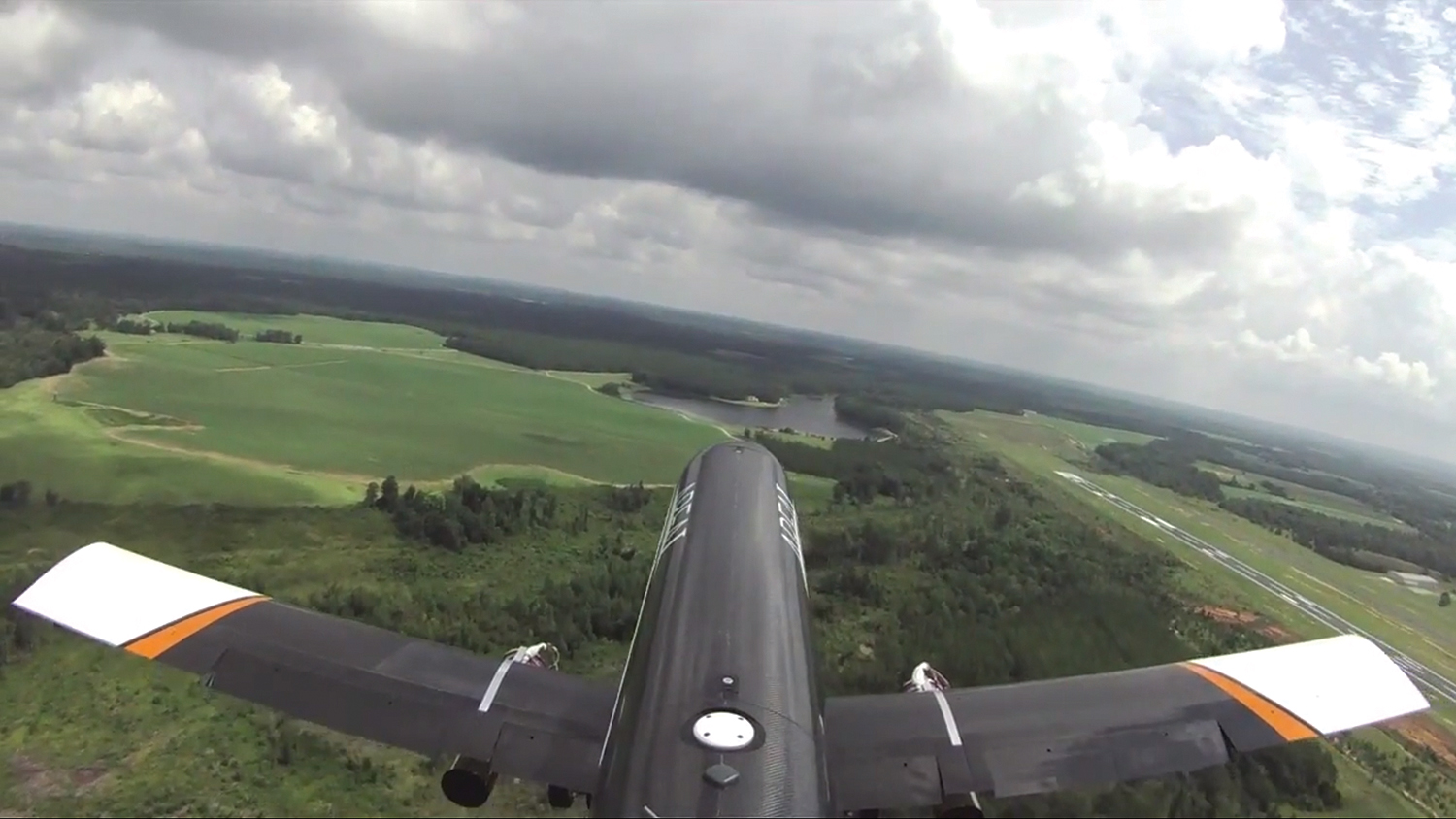
Prandtl Flying Wing
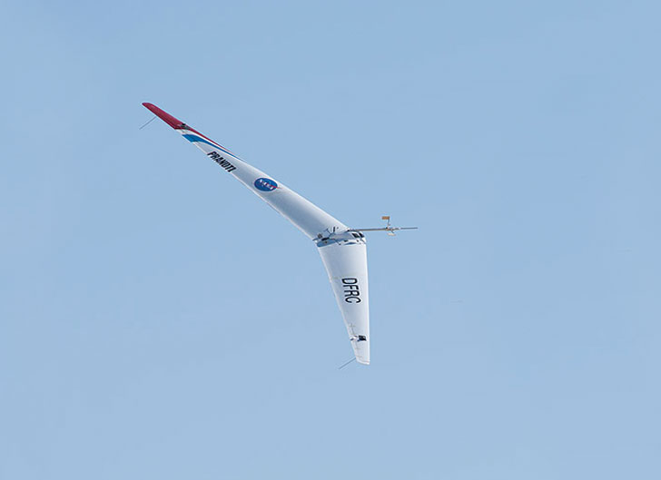
Armstrong researchers are continuing to test a new wing shape that could significantly increase aircraft efficiency. The team has built upon the research of German engineer Ludwig Prandtl to design and validate a scale model of a non-elliptical wing that reduces drag and increases efficiency. By allowing for longer wingspans, the new design produces 12 percent less drag than current solutions. In addition, the approach to handling adverse yaw employs fine wing adjustments rather than an aircraft’s vertical tail. In a propeller application, efficiency could increase by 13 percent. If the concept continues to prove its value, it could advance NASA’s research goals to verify technologies leading to significant fuel economy and emissions reduction.
Work to Date
The team has developed, demonstrated, and validated scale models of an improved Prandtl -D wing, and their flight experiments have unequivocally established proverse yaw. The innovation was patented, and research has led to work on an autopiloted flying wing designed to land on Mars. In 2018 and 2019, the team completed test flights incorporating pressure sensors embedded in the wing. Preliminary data demonstrated the projected lift distribution.
Looking Ahead
Researchers are exploring ways this innovation can benefit NASA projects. In addition, the wind energy industry is open to new bladed designs that improve efficiency, and this market segment is large and growing.
Benefits
- Highly efficient: Increases total aircraft efficiency by as much as 62 percent, including efficiency increases in drag reduction (12 percent) and when used in propeller systems (13 percent)
- Economical: Improves fuel efficiency by allowing aircraft to fly faster
- Safer: Reduces adverse yaw when correcting for roll
Applications
- Mid-size commercial aircraft
- Wind turbines
- Drones and unmanned aircraft
- Industrial fans
- Energy delivery systems
PI: Oscar Murillo | 661-276-6110 | Oscar.J.Murillo@nasa.gov
New Propeller/Fan
Armstrong researchers are working on design processes for propeller blades that are intended to increase efficiency and reduce aerodynamic noise. Based on wing design improvements derived from the Prandtl aircraft, this innovative design uses an alternative spanload to redistribute the propeller loading. These designs are intended to optimize the power needed to rotate a propeller or fan. Initial estimates indicate 15 percent improvement in propulsive efficiency and noise reduction. If successful, the benefits could be realized for a wide range of propeller and fan designs.
Work to Date
The current research effort focuses on a propeller/fan redesign to be used as comparison and quantification of results. Researchers will use the modeling and analysis of a known and tested propeller to generate models, compare these results to wind tunnel results, and refine a workflow to assess future propeller configurations. The end result is expected to be a simplified design process resulting from modeling and testing.
Benefits
- Efficient: Redistributes lift and drag along the propeller or fan blade, reducing power consumption while producing the designed thrust
- Economical: Allows blades to use less power, reducing fuel costs
- Quieter: Produces less noise than conventional blade designs
- Simpler: Provides a solution that can be coupled with several airfoil designs
Applications
- Propellers
- Industrial fans
- Axial compressors
- Power turbines
PI: Jason Lechniak | 661-276-2620 | Jason.A.Lechniak@nasa.gov
Glider Swarm Sensor Distribution
Martian surface observations are collected remotely via satellites or with localized landers and rovers. Researchers from Armstrong and NASA’s Jet Propulsion Laboratory are collaborating to create preliminary concepts, systems development, and prototypes for small unmanned aerial systems (UAS) capable of deployment and flight on Mars. The goal of the UAS swarm is to deliver sensors through the atmosphere to create a distributed mesh sensor network to collect surface and atmospheric measurements. The technology could also be used on Earth for atmospheric observations.
Work to Date
With NASA’s Center Innovation Fund resources, the team developed designs for prototype Mars gliders that span 13 inches, 18 inches, and 24 inches. They then fabricated and flew a 24-inch model on a UAS mothership. In order to prototype the glider swarm on Earth, researchers developed balloon and blimp operations concepts. They designed, developed, and operated a gondola from a tethered blimp. The 24-inch model was then flown from the tethered blimp to conduct tests of release, handling, and glider performance.
Looking Ahead
The 13-inch and 18-inch gliders will be flown in 2020. System-level swarm testing in a low-altitude setting is also planned for 2020.
Collaborators
NASA’s Jet Propulsion Laboratory
Benefits
- Breakthrough: Characterizes small glider distribution performance in free and directed flight
- Efficient: Provides a low-cost, low-mass sensor distribution architecture for novel atmospheric observations
- Innovative: Enables Armstrong researchers to analyze, develop, and test in a new flight regime while participating in planetary science platform development
PI: David Berger | 661-276-5712 | Dave.E.Berger@nasa.gov
Investigating Laminar Flow
Researchers at NASA’s Langley Research Center have developed a new crossflow suppression technique for aircraft wings with moderate sweep. Armstrong is contributing to the effort with flight tests to confirm that the new technique works as predicted in a flight environment. Known as Crossflow Attenuated Natural Laminar Flow (CATNLF), the technique enables laminar flow by reshaping wing airfoils to obtain specific pressure distribution characteristics that control the crossflow growth near the leading edge. This research could potentially be useful in future commercial transports to reduce aerodynamic drag and increase efficiency.
The CATNLF research is three separate flight test efforts.
ReHEAT
ReHEAT is the first flight test of a technology previously tested in a wind tunnel to improve flow visualization of the boundary layer. Testing involves painting a carbon-based, electrically conductive coating onto a test surface. Electrical current is passed through the coating, which heats the surface. In a wind tunnel, the coating is covered with temperature-sensitive paint for flow visualization. During flight tests, an infrared camera is used for visualization.
Work to Date
The coating was applied to a supersonic natural laminar flow test article at Armstrong. The coated test article was flown on the centerline pylon of the F-15B research testbed, along with an infrared camera system. During flight tests in summer 2019, the heating layer worked as expected and the infrared camera successfully visualized the boundary layer state.
Looking Ahead
Next steps are to coat the CATNLF test article with the same coating to achieve similar improvements to the flow visualization of the boundary layer.
CLIP Flow Rake
CLIP Flow Rake is a vertically oriented instrumentation rake with air data and disturbance probes that will map the flow field under the F-15B testbed to support the follow-on test with the CATNLF laminar flow test article. Flow field mapping will be instrumental for understanding the data that will be collected during the CATNLF flight tests.
Work to Date
A contractor has completed the mechanical design and fabrication and will deliver the rake to Armstrong early in 2020.
Looking Ahead
The team expects to flight-test the rake in summer 2020.
CATNLF Laminar Flow Test Article
The CATNLF laminar flow test article is a stub wing mounted vertically under the F-15B testbed aircraft. Langley researchers are designing the test article to achieve significant runs of natural laminar flow at Reynolds numbers up to 30 million. A leading- edge sweep of 35 degrees will demonstrate that the technology can attenuate the crossflow boundary layer transition mechanism, which is the dominant transition mechanism on wings with moderate to high sweep.
Work to Date
The design of the outer mold line necessary to achieve natural laminar flow will be completed in early 2020. An outside contractor will then perform the detailed mechanical design and fabricate the test article.
Partner
NASA’s Langley Research Center
Benefits
- Small and light: Offers 100 times the number of measurements at 1/100 the total sensor weight
- Improves safety: Provides validated structural design data that enable future launch systems to be lighter and more structurally efficient
- Multiple modalities: Measures multiple parameters in real time
Applications
- Commercial subsonic transports
PI: Mike Frederick | 661-276-2274 | Mike.Frederick-1@nasa.gov
Spanwise Adaptive Wing Research
Researchers recently concluded the feasibility assessment of the Spanwise Adaptive Wing (SAW) concept, which will allow part of an aircraft’s wing to fold in flight, boosting efficiency and performance. SAW seeks to enhance aircraft performance by allowing the outboard portions of wings to fold according to various flight condition demands. A mechanical joint, acting as a hinge line for rotation, makes the freedom of movement possible. New advancements in shape memory alloy (SMA) actuators allow tighter packaging, enabling the folding of much smaller wing sections.
Work to Date
To demonstrate SAW in flight, researchers designed an experiment to fly on the Prototype-Technology Evaluation Research Aircraft (PTERA), developed by Area-I. In a three-flight series, the outer portion of the wing was folded through a range of +70° to –70°. These tests demonstrated that SAW augmented the yaw control of the aircraft to a point where the rudder could be entirely removed while still maintaining controlled flight. Additionally, an algorithm was developed that incorporated the flight test data to continuously change wing tip position to identify the lowest drag setting, thus increasing fuel efficiency.
Parallel to the flight test effort, researchers at NASA’s Glenn Research Center developed, built, and tested a full scale SMA actuator for the outer portion of an F/A-18 wing to demonstrate actuator scalability. The actuator is capable of 20,000 inch-pounds of torque and can articulate over 90°.
Looking Ahead
A follow-on project is being formulated in which SAW can be tested at an even more relevant scale.
Partners
NASA’s Langley and Glenn Research Centers, The Boeing Company, and Area-I
Benefits
- Increased efficiency: Increases aircraft stability and wing compression lift
- Increased performance: Augments yaw power and stability
- Adaptive: Enables optimal wing position for all flight positions
Applications
- Commercial, military, and general aviation aircraft
PI: Matthew Moholt | 661-276-3259 | Matthew.R.Moholt@nasa.gov
Airborne Research Test System
This research effort evaluated the feasibility of the Airborne Research Test System (ARTS), acting as a flight controller, to command the outboard ailerons on movable-span sections of the Prototype-Technology Evaluation and Research Aircraft (PTERA) testbed. The ARTS is a hardware and software platform for testing advanced control and sensor concepts. It reduces the effort and cost of flight-testing research by providing a flexible, reconfigurable computing platform for hosting research experiments. This research was part of the Spanwise Adaptive Wing (SAW) project, which investigated the use of control surfaces to allow the outboard portions of wings to adapt, or fold, to adjust to various flight condition demands.
Work to Date
The ARTS box was tested in full non-linear simulation, and the PTERA testbed and the ARTS successfully exchanged sensor information and control surface commands. The system was also successfully tested in hardware-in-the-loop in a real-time operating environment. Three flight tests gathered data that was used to update the ARTS control laws. In late 2018 and with the ARTS box onboard, the PTERA testbed was destroyed during a crash into the dry lakebed outside Armstrong, and there are no plans for future flight tests. This research contributed valuable information to NASA’s research knowledge about aircraft with wings that have movable spans.
Looking Ahead
The PTERA simulation with the ARTS setup is being actively used for student research.
Benefits
- Compatible with Simulink® software: Saves time and resources
- Flexible: Provides an array of options to test and implement advanced control concepts
- Configurable: Can be quickly customized for various experiments
- Partitioned: Separates research experiments from the core system
Applications
- Operate as a flight controller
- Validate new flight control concepts
- Test aircraft limits
PI: Peter Suh | 661-276-3402 | Peter.M.Suh@nasa.gov
Simulink is a registered trademark of MathWorks, Inc.
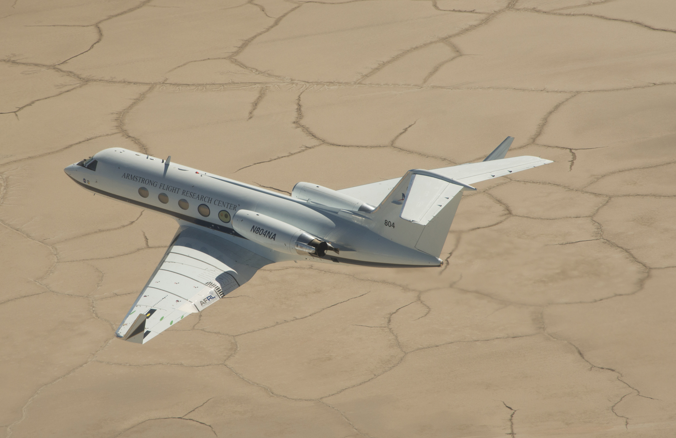
Alternative Fuels

Armstrong’s flight expertise and airspace are being leveraged to support a series of tests that will study the effects of alternate biofuel on engine performance, emissions, and aircraft-generated contrails at altitude. Sponsored by NASA’s Langley Research Center, the ACCESS-II flight experiment involves flying a DC-8 aircraft as high as 38,000 feet while three instrumented aircraft—a Langley HU-25C Guardian, a Falcon from the German Aerospace Center (DLR), and a T-33 from the National Research Council of Canada (NRC)—trail behind at distances ranging from 300 feet to more than 10 miles and measure exhaust fumes from the DC-8 engines. During the flights, the DC-8 engines will be powered by conventional fuel and a blend of two other mixes of conventional fuel and an alternative biofuel. More than a dozen instruments will characterize the soot and gases collected from the DC-8, monitor the way exhaust plumes change in composition as they mix with air, and investigate the role emissions play in contrail formation.HU-25C Guardian, a Falcon from the German Aerospace Center (DLR), and a T-33 from the NRC—trail behind at distances ranging from 300 feet to more than 10 miles and measure exhaust fumes from the DC-8 engines. During the flights, the DC-8 engines will be powered by conventional fuel and a blend of two other mixes of conventional fuel and an alternative biofuel. More than a dozen instruments will characterize the soot and gases collected from the DC-8, monitor the way exhaust plumes change in composition as they mix with air, and investigate the role emissions play in contrail formation.
Work to Date
A pair of ground-based studies in 2009 and 2011 measured a DC-8’s exhaust emissions as the aircraft burned alternative fuels. Flight experiments in 2013 occurred with the sampling HU-25C Guardian aircraft flying behind the DC-8.HU-25C Guardian aircraft flying behind the DC-8.
Looking Ahead
Data collection and analysis will be conducted by Langley, and Armstrong will provide the lead aircraft, pilots, and airspace. Representatives from Canada and Germany will participate in the experiments, as those countries also are interested in wake vortex and emissions research.
Partners
Langley, NRC, and DLR
Benefits
- Aids research: Will enable the collection of real-time data about engine fumes to better understand the chemistry of combustion byproducts and aid in the evaluation of alternative jet fuels
- Reduces pollution: Will contribute to the design of cleaner jet engines
Applications
- Alternative fuel research
- Wake vortex flight research and industrial processes
Aeroservoelastic Technologies
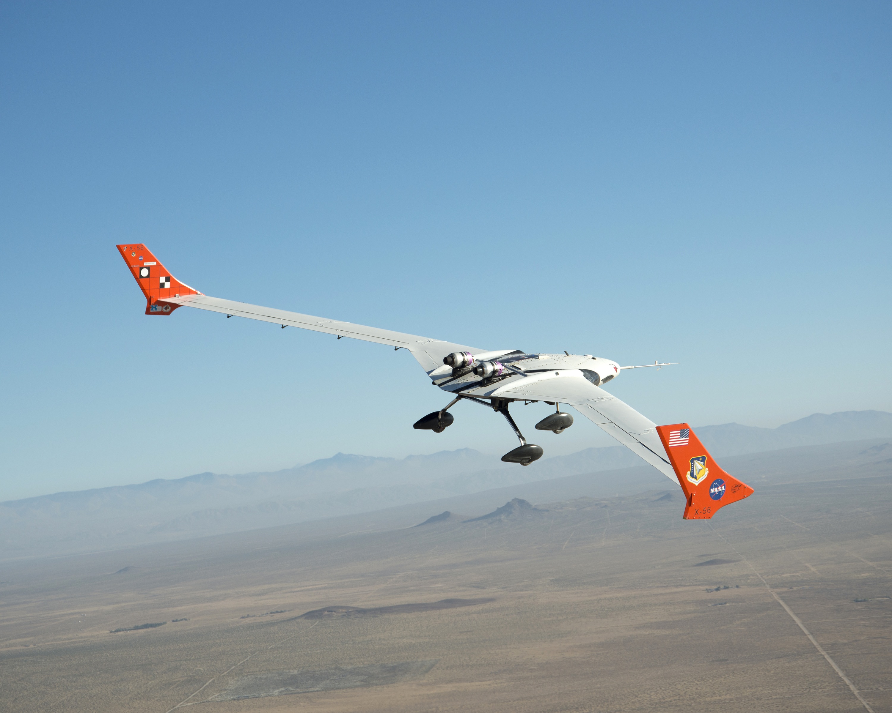
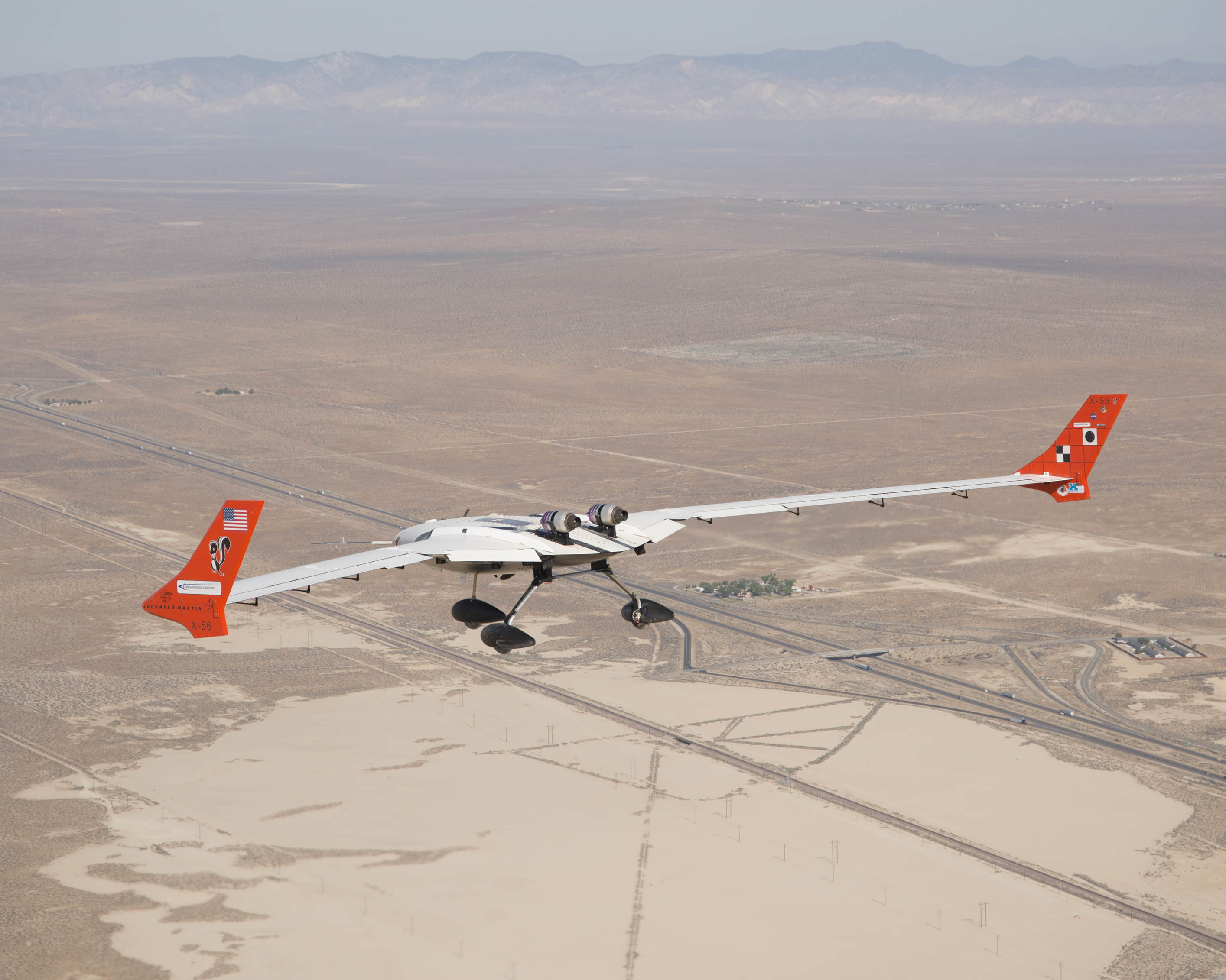
Longer and more flexible wings are considered crucial to the design of future long-range, fuel-efficient aircraft. Because these wings are more susceptible to flutter and the stress of atmospheric turbulence, NASA is investigating key advanced control technologies for active flutter suppression and gust load alleviation. The X-56A aircraft is intended to facilitate the development of tools and technologies and acquire data to validate modeling techniques. The goal is to advance aeroservoelastic technology through flight research using a low- cost, modular, remotely piloted experimental aircraft. The aircraft is being tested using flight profiles where flutter occurs in order to demonstrate that onboard instrumentation not only can accurately predict and sense the onset of wing flutter but also can be used by the control system to actively suppress aeroelastic instabilities.
This work has applicability beyond flight safety and design optimization. Lessons learned with the X-57A aircraft can be applied to other vehicles, such as supersonic transports, large space structures, and unpiloted aircraft.
Work to Date
In 2018 and 2019, the aircraft’s envelope with the flexible wings was expanded. This culminated with flights at speeds beyond flutter, demonstrating the use of active flight controls for the suppression of flutter. To date, a total of 39 flights have been conducted by NASA.
Looking Ahead
The team will transition to flight testing a new set of wings developed by Northrop Grumman to continue its research on highly flexible wings.
Partner
Air Force Research Laboratory
Benefits
- Enables new technology: Facilitates construction of longer, lighter, more flexible wings for crewed and remotely piloted aircraft
- Configurable: Enables a vast array of future research activities for wing sets, tail sections, sensors, and control surfaces
PIs: Jacob Schaefer | 661-276-2549 | Jacob.Schaefer
Matt Boucher | 661-276-2562 | Matthew.J.Boucher@nasa.gov
Alex Chin | 661-276-2681 | Alexander.W.Chin
Jeff Ouellette | 661-276-2152 | Jeffrey.A.Ouellette
Peter Suh | 661-276-3402 | Peter.M.Suh@nasa.gov
X-56A Controllers
The X-56A Multi-Utility Technology Testbed (MUTT) research team suppressed body freedom flutter with a modern and a classical controller during flight tests in 2018 and 2019. These two mathematical ways of directing the aircraft were instrumental in enabling the team to advance research on lightweight, flexible aircraft wings. The primary challenge for control of body freedom flutter is to both automatically track vehicle flight control commands and suppress flutter within the pilot’s stick frequencies. The two objectives conflict and must be carefully addressed in the control law design. The goal of this research is to develop robust controllers that can safely extend the control envelope for commercial aircraft.
Work to Date
The X-56A team completed flight tests demonstrating that the controllers successfully suppressed flutter. The primary purpose of the classical controller was to collect data to enable use of the more complex and advanced control system. The modern controller permitted the aircraft to operate safely at higher speeds, suppressing flutter deeper into the regions where the aircraft is less stable. To prove the effectiveness of the flutter suppression, researchers implemented a sequence of flight maneuvers where the controller was
turned off—for less than 2 seconds as the aircraft approached flutter—allowing the flutter mode to grow uncontrolled. When the system reactivated after a set time, the controller stabilized the flutter mode and lessened the oscillations.
Looking Ahead
The team is analyzing data and will be presenting and publishing results. Future work will involve replacing the highly flexible wings with stiffer wings for more research.
Benefits
- Enables more design freedom: Contributes to the development of robust controllers that will enable designers to consider lighter and/or larger wing profiles
- Increases safety: Reduces the likelihood of losing control of aircraft
Applications
- Civilian and military aircraft subject to body freedom flutter in their flight envelope
- Multi-objective control designs in any industry with conflicting tracking and regulation objectives
PI: Peter Suh | 661-276-3402 | Peter.M.Suh@nasa.gov
Structural Dynamics Ground Testing
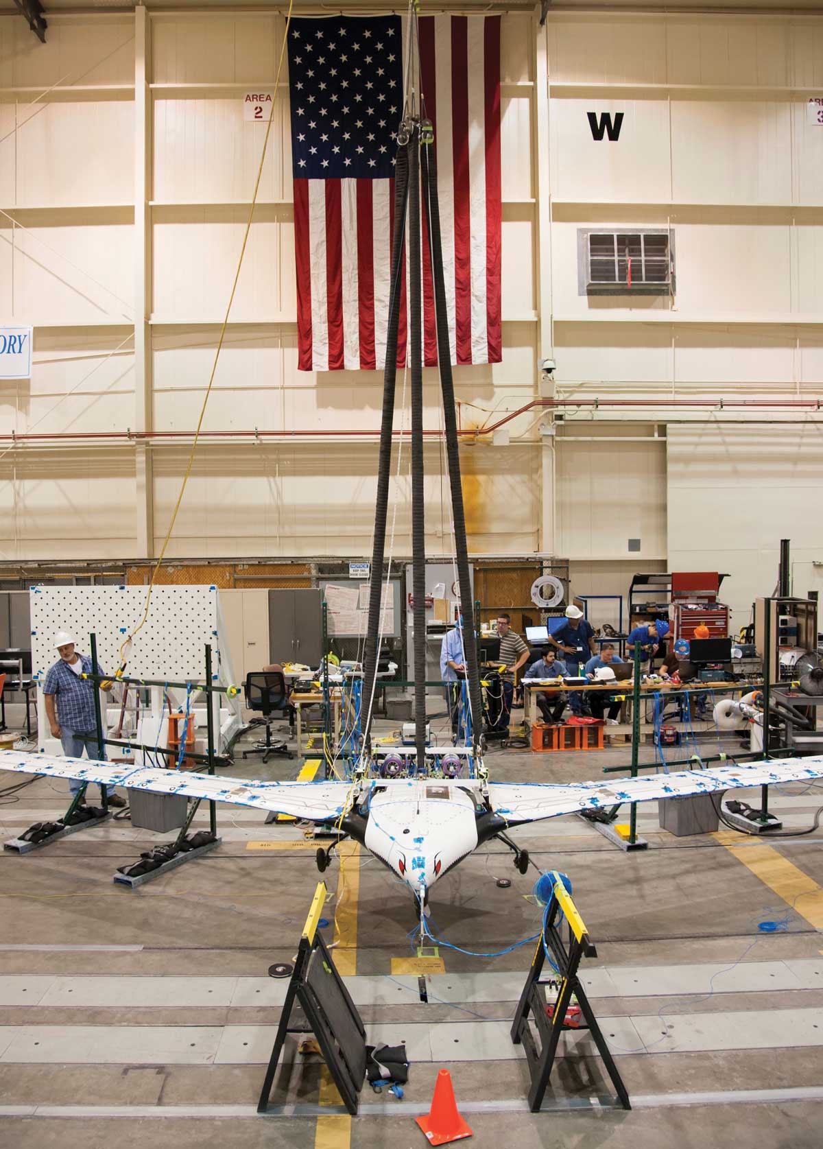
Structural dynamics ground tests were a key part of preparing the X-56A Multi-Utility Technology Testbed (MUTT) for flight tests. The aircraft is designed for high-risk aeroelastic flight demonstration and research. Therefore, model validation for the X-56A was especially important because the structural model was used to develop a flight control system with active flutter suppression capabilities. The team conducted a series of tests to validate structural models and overcame several challenges to produce valuable information that the team is already applying to structural dynamics testing with a similar vehicle.
Work to Date
The team performed three separate sets of tests in Armstrong’s Flight Loads Laboratory to validate the X-56A structural models. First, ground vibration testing (GVT) was conducted with both the wing by itself (attached to a strongback) and the complete vehicle at two mass conditions (empty and full fuel). Then the team studied two boundary conditions for the complete vehicle (on landing gear and suspended free-free). The original soft-support test configuration for the GVT used multiple bungees that resulted in unforeseen coupling interactions between the bungees and the vehicle structural modes. The team resolved this issue by adapting the test setup via multiple iterations.
Second, pitch moment of inertia (MOI) tests were conducted using a compound pendulum method and repeated with two different pendulum lengths for independent verification. Third, wing proof loads tests were performed by attaching the wing to a strongback and applying loads. These tests helped verify the wings of X-56A were sufficiently characterized for model validation and strong enough to withstand various flight loads during flight tests.
Looking Ahead
The team is applying lessons learned with the X-56A aircraft to a new set of GVTs for the X-56B, which has similar wings.
Benefits
- Saves resources: Enables testing of emerging approaches and test techniques in a safe environment
- Cutting edge: Advances knowledge in the field of structural dynamics testing
Applications
- Structural dynamics testing
PI: Alexander Chin | 661-276-2681 | Alexander.W.Chin@nasa.gov
Flexible Aircraft Systems
This research effort focused on designing multi-sine programmed test inputs for use in flexible aircraft system identification situations. In this context, system identification is the process of exciting aircraft and control system dynamics, collecting flight data measurements, and constructing models from the data.
For the X-56A Multi-Utility Technology Testbed (MUTT) aircraft, system identification was needed to refine and validate preflight aerodynamic and aeroelastic predictions and to verify robust stability of flight control laws. System identification as applied to the X-56A aircraft entailed modeling the response to as many as 10 separate control surfaces and two engines.
The Armstrong team applied optimization techniques to select excitation frequencies, amplitudes, and phases in order to efficiently generate data with a high signal-to-noise ratio across a wide frequency band while maintaining a margin with respect to operating limitations. While this approach was tailored toward flexible aircraft, it is applicable to any complex system identification problem where manually tailoring the excitation is impractical. In addition to validating preflight predictions and control system design, the approach is useful for computational fluid dynamics simulation to reduce expensive computation time.
Work to Date
The X-56A flexible wing flight test campaign was completed and included 27 flights in 2018 and 2 in 2019. Low-order equivalent systems and state-space models were estimated from the flight data, in some cases at flight conditions beyond the flutter boundary.
Looking Ahead
The multi-sine programmed test inputs will be applied to the new X-56B configuration data in 2020, reducing required flight test time and reducing costs for future industry partners.
Partner
NASA’s Langley Research Center
Benefits
- Powerful: Generates high-quality flight data quickly and safely
- Efficient: Promotes real-time and onboard data reduction for control room monitoring
Applications
- Fundamental research
- Control system requirements verification
PI: Matt Boucher | 661-276-2562 | Matthew.J.Boucher@nasa.gov
Flight Control Systems
This research effort is developing flight control systems and mathematical models that integrate both structural and flight dynamics. As modern aircraft become more flexible and these disciplines converge, conflicts arise between independently developed modeling methodologies. Because the structural and flight dynamics of the X-56A Multi-Utility Technology Testbed (MUTT) aircraft are acutely coupled, resulting models are capable of capturing the requirements of both disciplines.
Work to Date
The Armstrong team’s linear models have been validated in flight tests with the X-56A flexible wings at speeds beyond the open flutter. The models are able to accurately predict the point of instability and were applied to the design and evaluation of the flight control laws used to stabilize the structure. The unsteady aerodynamic and structural data has been integrated with a non-linear piloted simulation. The piloted simulation allows for evaluation of the dynamics and development of pilot techniques in highly non-linear conditions, such as takeoff and landing, enabling the safe operation of the X-56A.
Partner
Air Force Research Laboratory
Benefits
- More design freedom: Enables the design of lighter, larger, and more flexible wing profiles
- Economical: Increases fuel efficiency
- Safer flight: Reduces likelihood of structural damage
- Innovative: Advances the state of the art for higher aspect ratio wing and enables future N+3 commercial aircraft concepts (i.e., three generations beyond the current commercial transport fleet)
PIs: Jeffrey Ouellette | 661-276-2152 | Jeffrey.A.Ouellette
Jacob Schaefer | 661-276-2549 | Jacob.Schaefer
Peter Suh | 661-276-3402 | Peter.M.Suh@nasa.gov
Adaptive Compliant Trailing Edge
The ACTE experimental flight research project is a partnership between NASA and the U.S. Air Force Research Laboratory (AFRL) with the purpose of investigating whether advanced flexible trailing-edge wing flaps can be designed and integrated onto an aircraft. The eventual goal of the ACTE technology is improving aerodynamic efficiency and reducing noise associated with landings. The experiment involves replacing the conventional Fowler flaps of a Gulfstream III (G-III) research testbed aircraft with advanced, shape-changing ACTE flaps that form continuous bendable surfaces. The ACTE flaps are manufactured by FlexSys, Inc., and the primary goal of the experiment is to collect flight data about the integration and reliability of the flaps. This radically new morphing-wing technology has the potential to save millions of dollars annually in fuel costs and reduce drag and airframe weight.
Work to Date
The G-III has been converted and instrumented into a test platform, and the first set of test flights was completed in April 2015. The test team met expectations by completing all primary and secondary objectives on schedule and within budget. Specific achievements include:
- Completed –2° to 30° tests
- Collected structural and aerodynamic data
- Characterized the structural performance of the flap
Benefits
- Innovative: Advances compliant structure technology for use in aircraft to significantly reduce drag, wing weight, and aircraft noise
- Economical: Reduces drag and increases fuel efficiency through the use of an advanced compliant structure
Applications
- Aircraft control surfaces
- Helicopter blades and wind turbines
PI: Ethan Baumann | 661-276-3417 | Ethan.A.Baumann@nasa.gov
Wing Deflection Measurement System
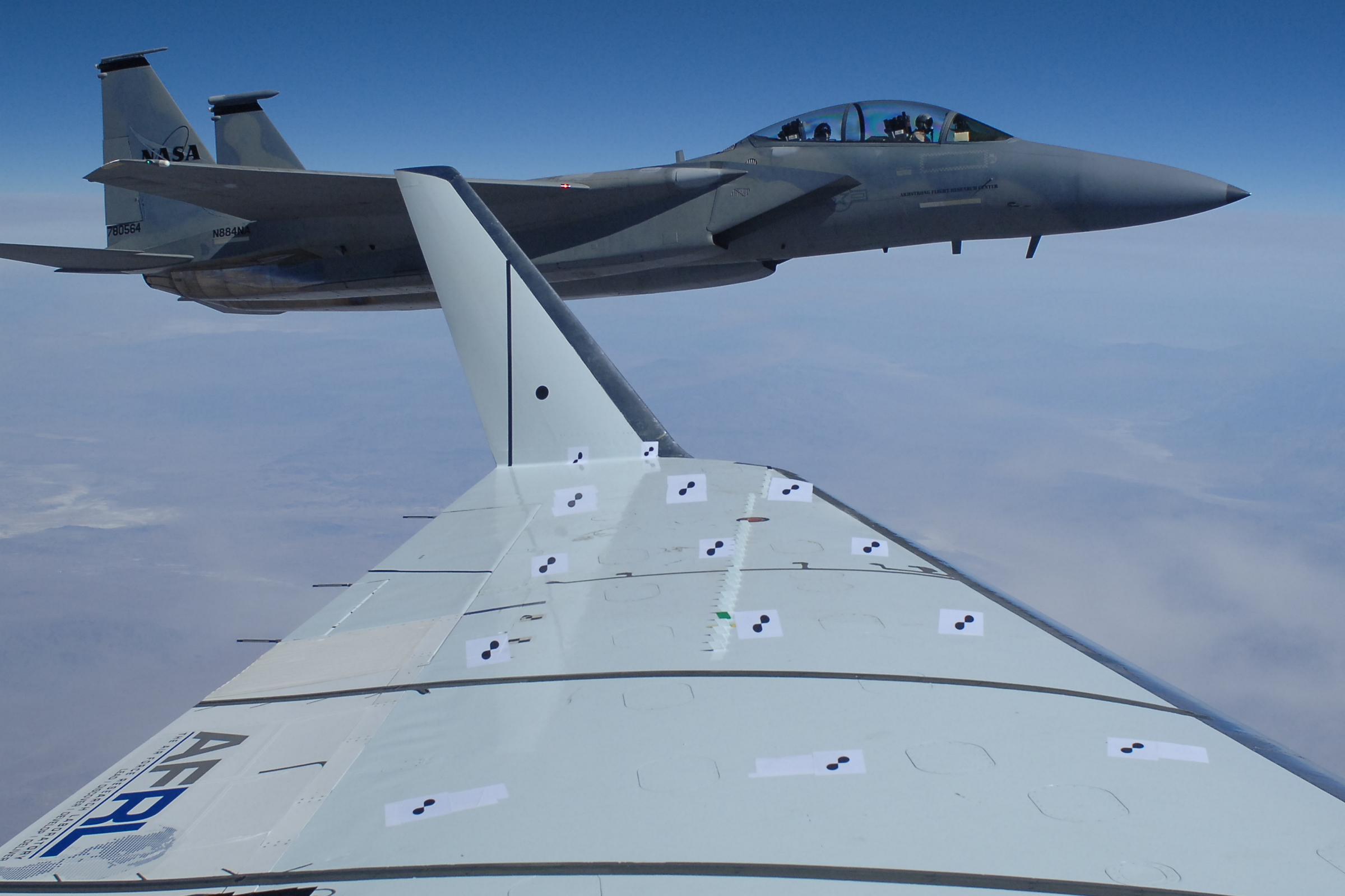
Measuring wing deflection and twist during flight is necessary to improve the design of next-generation aircraft wings. Innovators at Armstrong have developed a measurement system that uses photogrammetric methods to measure wing deflection and twist in real time with a high degree of availability and accuracy. The primary goal of this research is to test and improve the fidelity of current aerodynamic and structural models. A better understanding of wing dynamics and structural responses will enable more efficient and predictable wing designs. Real-time wing shape information can also be leveraged to implement active flutter control, apply adaptive control of aeroelastic structures, and even correct pilot-induced errors. An additional goal of the research is to evaluate using the Python open source programming language and the open source computer vision library OpenCV.
Work to Date
The measurement system was developed for use on the Gulfstream III (G-III) Subsonic Research Aircraft Testbed (SCRAT) and deployed for the ACTE flight experiment. Post-flight data were evaluated after the system captured the G-III wing at 1 Hz through the ACTE flight tests. The system performed well and provided consistent results.
Looking Ahead
The system will be upgraded with a new camera capable of capturing images at 25 Hz and a computer to process those images at a similar frame rate. Previous algorithms required a consistent target shape, but this constraint will be removed from future versions. The team is planning to test the new system during flight tests in summer 2016.
Benefits
- Flexible: A better understanding of wing shape could be used to exploit other development technologies, such as structural model validation, adaptive control systems feedback, and health system monitoring.
- Adaptable: The system can be implemented by other flight test organizations to collect data to evaluate aerodynamic and structural wing models.
Applications
- Wing deflection and twist measurements
- Flutter control
- Adaptive control of aeroelastic structures
Morph Aircraft Structures
Armstrong innovators are part of a team that is investigating whether SMAs can be used to morph aircraft structures. SMAs are materials that can be deformed at low temperatures and recover their original shape upon heating. The biomedical industry has leveraged their elastic attributes for numerous medical devices, but they have only recently been utilized in aviation. NASA’s Glenn Research Center is developing robust, high- temperature SMAs, and this research team is examining their potential use in aviation applications. If properly harnessed, these materials could become a lightweight, solid-state alternative to conventional actuators such as hydraulic, pneumatic, and motor-based systems.
Work to Date
As part of this collaborative multi-Center research effort, Armstrong is performing tests with the subscale demonstration Prototype Test Evaluation Research Aircraft (PTERA). Goals are to (1) develop and vet an SMA actuator and control system that can be employed on larger systems, (2) experimentally determine aircraft flight response, and (3) validate analysis tools and develop larger actuators with quicker excitation methods. Aerodynamic analysis has quantified the flight handling response and benefit of the morphing structure. Upon completion of the subscale effort, the team is planning to use a NASA F-18 aircraft for full-scale demonstration of morphing structures.
The team is also working with actuator integration, using a proprietary material developed at Glenn.
Looking Ahead
Planning is underway for flight tests in 2017. The team will also begin designing the initial groundwork for the full-scale F-18 demonstration.
Partners
NASA’s Glenn and Langley Research Centers; The Boeing Company; and Area-I, Inc.
Benefits
- Adaptive: Aids in the development of aero structures that will improve aircraft performance and fuel economy, due to small footprint but high energy density
- Decreases maintenance: Enables simpler designs that require fewer repairs
Applications
- Commercial, military, and general aviation aircraft
PI: Matthew Moholt | 661-276-3259 | Matthew.R.Moholt@nasa.gov
Hyperelastic Materials
This research effort seeks to fill in knowledge gaps that currently exist in the fundamental understanding of hyperelastic materials, including their response under static and dynamic loading, and to explore their potential for application to structures in flight. Hyperelastic materials have been proposed as a continuous mold line–enabling technology for future generations of aircraft design. However, the data required to prove their flight-worthiness and practical application are not readily available. The outcome of this research effort is contributing to component data currently lacking and providing insight into the behavior of hyperelastic materials in flight that has not been previously explored.
Work to Date
Three project tasks were developed to gather biaxial strain data, evaluate concentration factors, and validate analytical mode shapes and frequencies for test coupons of hyperelastic materials under a range of stretch ratios. The three areas investigated were approached via three subtasks: biaxial testing, stress concentration studies, and dynamic testing.
Looking Ahead
An effort is underway to design a small flight test project that will subject panels of hyperelastic material to transonic and supersonic flight conditions. The objective is to further understand the behavior of hyperelastic materials in flight applications, particularly panel flutter and panel-type responses. The general concept involves installing hyperelastic panels on the flight test fixture of NASA’s F-15 supersonic flight testbed. NASA’s Langley Research Center and Ames Research Center are potential partners for this effort.
Benefits
- Innovative: Increases the reliability of hyperelastic materials in flight applications
- High performance: Improves aerodynamic capabilities and enables morphing structural technologies by sealing structural gaps
Applications
- Aircraft/Spacecraft control surfaces
- Motor vehicles, trains, and ships
- Industrial engines (e.g., vibration damping)
PI: Claudia Herrera | 661-276-2642 | Claudia.Herrera-1@nasa.gov
Inverse Finite Element Method
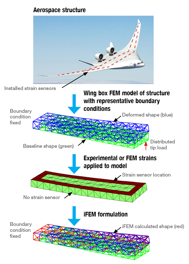
This research project is evaluating an innovative technique that uses experimental strain sensors to measure structural deformations and full-field strains in aerospace structures. An iFEM analysis reconstructs a deformed structural shape based on the experimental strain measurement data or strains simulated by FEM analysis to represent the in situ strain measurements. Mapping the iFEM displacement solution onto a full FEM model without the applied loading allows the complete fields of displacement, strain, and stress to be reconstructed to a high degree of accuracy. The innovation improves safety by enabling more efficient health monitoring of control surfaces and flexible structures. This project supports work on multiple flight research projects at Armstrong.
Work to Date
The team has completed and validated a FEM code utilizing a three-node flat shell element.
Looking Ahead
Future plans involve developing and validating the algorithm on a full-size flight test article.
Benefits
- Accurate: Enables accurate full-field structural shape and strain measurement
- Economical: Uses a minimal number of sensors to recreate the full-field structural deformations and strains
Applications
- Aircraft wing flaps
- Helicopter blades
- Wind turbines
- Motor vehicles
- Trains
- Ships and submersibles
PI: Eric Miller | 661-276-7041 | Eric.J.Miller@nasa.gov
Control Allocation Optimization
This technology utilizes real-time measurements of vehicle structural load to actively respond to and protect against vehicle damage due to structural overload. The innovation uses control surfaces to actively constrain critical stresses measured by an array of strain gauges. The allocation algorithm optimally utilizes the control surfaces to control the aircraft motion while preventing overstresses in critical aircraft structure. This advanced allocation algorithm is implemented in a run-time assurance architecture that provides an additional layer of software protection and prevents algorithm/software errors from generating unsafe control commands. The complete technology effectively constrains the load at critical points while producing the control response commanded by a pilot—all within a software assurance paradigm with high reliability.
Work to Date
Using NASA’s Full-Scale Advanced Systems Testbed (FAST) aircraft, the Armstrong team targeted the aileron hinge connection as a critical control point. A 2013 flight experiment using the FAST aircraft produced successful results in flight of a prototype of the optimal control allocation algorithm. A recent effort has focused on developing a real-time model of the structural response of the wing, which is being coupled with an optimal control strategy. All of the software elements have been incorporated with a run-time assurance algorithm to provide real-time software assurance.
Looking Ahead
The aircraft simulation model is being reworked to incorporate additional structural elements. The FAST aircraft was decommissioned in 2013, and a new F/A-18 testbed is being instrumented to flight test this technology.
Benefits
- Effective: Identifies the optimum control surface usage for a given maneuver for both performance and structural loading
- Automated: Monitors and alleviates stress on critical load points in real time
- Assured: Validates algorithm outputs in real time to improve software reliability
Applications
- Jet aircraft
- Industrial robotics
PI: Chris Miller | 661-276-2902 | Chris.J.Miller@nasa.gov
Flexible Motion Controls
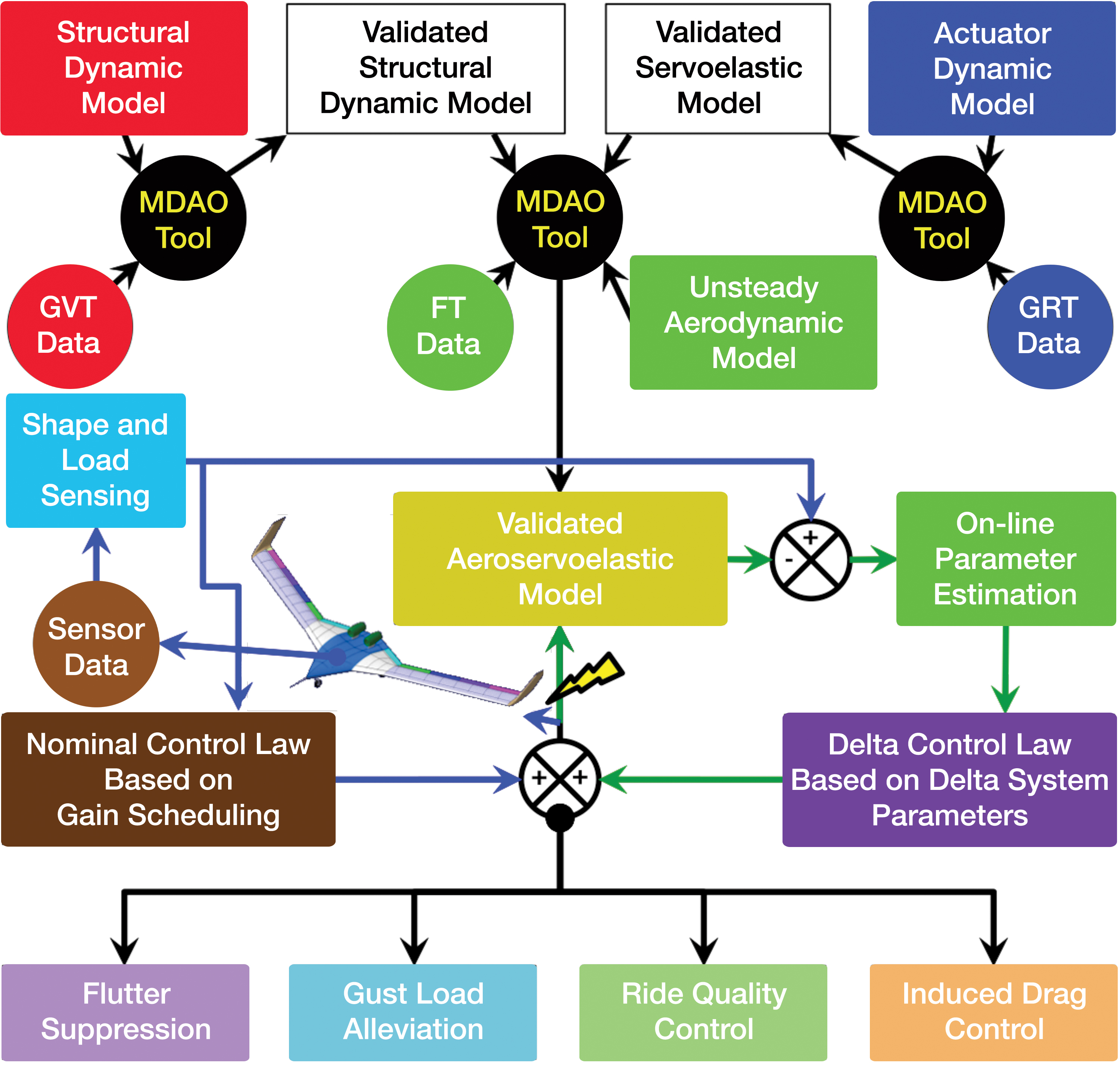
Most aeroservoelastic analyses of modern aircraft have uncertainties associated with model validity. Test-validated aeroservoelastic models can provide more reliable flutter speed. Tuning the aeroservoelastic model using measured data to minimize the modeling uncertainties is an essential procedure for the safety of flight. However, uncertainties still exist in aeroservoelastic analysis even with the test-validated model due to time-varying uncertain flight conditions, transient and nonlinear unsteady aerodynamics, and aeroelastic dynamic environments.
The primary objective of this research is to study the application of a digital adaptive controller to the flexible motion control problems by employing online parameter estimation together with online health monitoring. The second objective of this research is to develop a simple methodology for minimizing uncertainties in an aeroservoelastic model. Research is progressing in three primary areas.
Three-Dimensional (3D) Load Sensing from Measured Strain
This technology is a system and method for calculating wing deflection and slope over the entire surface of a 3D structure. The system integrates strain data measurements from discrete locations to compute out-of-plane deflection along fibers. It then uses a finite element model to interpolate and extrapolate all the deflections and slopes of the entire structure.
Aeroservoelastically Tailored Wings and Aircrafts with Curvilinear Spars and Ribs (SpaRibs)
For this project, a systematic multidisciplinary design, analysis, and optimization (MDAO) tool is employed to perform an optimization study and force the design flutter speeds back into the flight envelope. The approach combines an active control technique, aeroelastic control, and SpaRibs to increase design stability.
Test-Validated Aeroelastic Model of an Aircraft Using the Model Tuning Codes
This effort is seeking to reduce uncertainties in the unsteady aerodynamic model by employing a new flutter analysis procedure that uses the validated aeroelastic model. The research team has developed a technique to update unsteady aerodynamic models by matching the measured and numerical aeroelastic frequencies of an aircraft structure. In defining the optimization problem to match the measured aeroelastic frequencies, researchers select the variation of an unsteady aerodynamic force as the design parameter. This unsteady aerodynamic force is a function of Mach number, reduced frequency, and dynamic pressure, and it can be obtained from any aerodynamic model.
Looking Ahead
Work will aim to prove a tracking error convergence for the multi-input multi-output direct model reference adaptive control (MRAC) problem using a composite system construction with Lyapunov stability techniques. Performance of the proposed control design will be demonstrated through simulation of a linear version of an aircraft wing’s aeroelastic pitch and plunge dynamics.
The surrogate tracking error MRAC design will be extended to accommodate uncertainty in the locations of the nonminimum phase zeros. It will be implemented on more complex versions of the X-56A models and across a range of flight conditions to investigate its robustness. The delta control system design technique will also be applied to the cantilevered rectangular wing model.
Benefits
- High performance: Reduces uncertainties in the unsteady aerodynamic model of an aircraft to increase flight safety
- Economical: Enables high-precision simulation prior to expensive flight tests
- Efficient: Has the potential to improve fuel efficiency and ride quality
PI: Chan-gi Pak | 661-276-5698 | Chan-Gi.Pak-1@nasa.gov