


 |
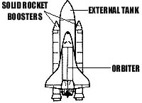
| Basic Parts of a Space Shuttle Credits: NASA |
The Space Shuttle is a Lifting Body
On August 12, 1977 a specially modified Boeing 747 jetliner was giving another aircraft a piggyback ride. Approximately 24,000 feet above the Mojave Desert a high-tech glider was released from its flying perch. It glided effortlessly without engine power to a smooth landing on the desert floor. A new era in space transportation had begun.
That high-tech glider was the space shuttle. The space shuttle is designed to simply ferry or “shuttle” people, satellites and other cargo between earth and space. It is a reusable spacecraft unlike any other that had come before it. It is a more efficient and economical vehicle as compared to its predecessors: capsules and rockets. The space shuttle, with a shape like a bulky glider, is actually a lifting body. A lifting body is a specially constructed spacecraft that cannot launch under its own power, but needs additional rocket engines for thrust. The space shuttle is a unique lifting body in that it is a high-tech glider.
Basic Structure
The space shuttle is made up of four parts: an orbiter (the shuttle itself), two solid rocket boosters (both reusable) and one external fuel tank (which is not reusable). This space craft is launched in an upright position attached to the 2 solid rocket boosters and the external fuel tank. At launch, the orbiter’s 3 main engines are fired (fueled by the external fuel tank) as well as the solid rocket boosters. Together they provide the shuttle with the millions of pounds of thrust to overcome the earth’s gravitational pull.
The Orbiter as a High-Tech Glider
The orbiter is shaped much like an airplane. It has many of the same parts as an airplane except for its engine configurations. The orbiter has wings that create lift. It uses a double-delta wing configuration to achieve the most efficient flight during hypersonic speed as well as providing a good lift -to-drag ratio during landing. For control, each wing has an “elevon”. An elevon is a combination of an elevator and an aileron. On an airplane, the elevator controls the motion of pitch (nose up, nose down). On most airplanes, the elevator is located on the horizontal stabilizer as part of the tail section. The ailerons are found on most airplanes at the trailing edge of each wing. Ailerons control an airplane’s roll motion. Because of the orbiter’s delta wing configuration, the elevators and ailerons are combined as elevons and placed at the trailing edge of each wing. The orbiter’s vertical stabilizer (fin) has the rudder which controls its yaw (nose left, nose right). The split-rudder on the orbiter works as a rudder and also as a speed brake (found on most airplanes as a spoiler located on the wing). It does this by splitting in half vertically and opening like a book. This deflects the airflow, increases drag and decreases the orbiter’s speed as it rolls along the runway upon landing.
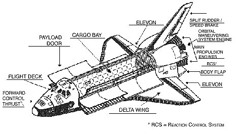 |
| The Parts of the Orbiter Credits: NASA |
The airplane-like control surfaces on the orbiter are useless in the vacuum of space. However, once the orbiter re-enters the earth’s atmosphere, these control surfaces interact with the air molecules and their airflow to control the orbiter’s flight path.
The engines are the major difference between this high-tech glider and airplanes. The orbiter has the OMS (orbital maneuvering system) engines as well as the RCS (reaction control system) engines. The shuttle maneuvers into orbit using its orbital maneuvering system (OMS). The OMS has 2 rocket engines located on the outside of the orbiter, one on each side of the rear fuselage. These rockets give the orbiter the thrust it needs to get into orbit, change its orbit, and to rendezvous with a space station or another space vehicle. The OMS is also used to exit orbit for re-entry into the earth’s atmosphere.
The second set of small engines is the reaction control system (RCS) engines. The RCS engines allow the commander to perform the motions of roll, pitch and yaw while the orbiter is moving out of orbit and into re-entry of the earth’s atmosphere. The RCS engines are also used while the orbiter is maneuvering in the upper atmosphere.
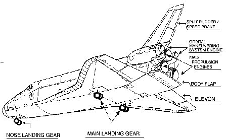 |
| The Parts of the Orbiter Landing Gear Credits: NASA |
Re-entry and Landing
The commander begins the de-orbit burn by firing the orbiter’s engines to slow its speed and take it out of orbit. Using the RCS engines, the orbiter is turned around so that it is moving backwards at a slower speed. To maneuver the orbiter while it is in this position, the commander uses the RCS engines to control roll, pitch and yaw motions. The OMS engines (space engines) are then fired, taking the orbiter out of orbit and thrusting it into the earth’s upper atmosphere. The RCS engines are used one last time to turn the orbiter around so that it is moving nose forward and pitched up slightly. In the upper reaches of the atmosphere the vehicle’s motions of yaw, pitch and roll are controlled by the RCS engines. As the atmosphere thickens, the airplane control surfaces become usable. The orbiter re-enters the atmosphere at a high angle of attack (about 30 degrees). This high angle of attack is used to direct most of the aerodynamic heating to the underside of the vehicle where the heat resistant tiles give the greatest amount of protection.
At an altitude of approximately 30 miles, the orbiter makes a series of maneuvers and S-turns to slow its speed. At 9.5 miles in altitude and at a speed of Mach 1, the orbiter can be steered using its rudder. The on-board computers fly the orbiter until it goes subsonic (slower than the speed of sound: Mach 1). This happens about 4 minutes before landing. At this time the commander takes manual control of the orbiter and flies a wide arc approach. At 7.5 miles from the runway, the orbiter is flying about 424 miles per hour at an altitude of 13,365 feet. About 2 miles from the runway, the orbiter is flying at nearly 360 miles per hour on a glide slope of 22 degrees.
Once lined up with the runway on approach, the orbiter continues its steep glide slope of 18 – 20 degrees. The commander levels the descent angle at a final glide slope of 1.5 degrees by performing a “flare maneuver”. The nose of the orbiter increases its pitch (noses up) which slows its speed. The orbiter touches down at a speed of about 215 miles per hour. It is slowed and eventually brought to a stop by the speed brake, wheel brakes and a drag chute.
It is this unique aerospace vehicle, a lifting body, that launches like a rocket, orbits like a spacecraft and lands like a glider that continues to link earth and space.