


9.0 HARDWARE AND EQUIPMENT
This section provides requirements applicable to the design of hardware and equipment. Requirements in this section apply to all hardware and equipment with which the crew interfaces—from large and complex systems such as ISS racks, to small items such as tools, drawers, closures, restraints, mobility aids, fasteners, connectors, clothing, and crew personal equipment. Hazard minimization is accomplished through hardware design, and design of interior components which crew may encounter, through nominal mission activities, including maintenance operations, and anticipated off-nominal events.
Equipment refers to items such as tools used to accomplish a task or activity. Equipment is a type of hardware, and therefore this term is sometimes used interchangeably with hardware.
Hardware refers to individual components of equipment, including but not limited to fasteners, panels, plumbing, switches, switch guards, and wiring. This term is sometimes used interchangeably with equipment.
9.1 Standardization
9.1.1 Crew Interface Commonality
[V2 9001] Hardware and equipment performing similar functions shall have commonality of crew interfaces.
[Rationale: The intent of this requirement is to ensure commonality and consistency within a given human spaceflight program. This facilitates learning and minimizes crew error.]
9.1.2 Differentiation
[V2 9002] Hardware and equipment that have the same or similar form but different functions shall be readily identifiable, distinguishable, and not be physically interchangeable.
[Rationale: The intent of this requirement is to avoid potential confusion crewmembers may experience that can lead to errors when items with similar form are not readily identifiable or physically distinguishable.]
9.1.3 Routine Operation
[V2 9003] Worksites shall be designed to provide rapid access to needed tools and equipment for routine/nominal operations.
[Rationale: Good design of systems and equipment can reduce the amount of time to perform many routine tasks, e.g., food preparation, maintenance, and inventory management. Having to retrieve, use, and stow tools for the routine/nominal operation of systems, hardware, and equipment can be especially cumbersome and burdensome for routine tasks. The ability to perform operations with promptness helps ensure proper use.]
9.2 Training
9.2.1 Training Minimization
[V2 9004] Hardware and equipment with which crew interact shall minimize the time required for training.
[Rationale: Generally, designers can minimize training by following requirements dictated in this NASA Technical Standard under section 9.1 Standardization, and Section 10 Crew Interfaces. However, a specific system may have characteristics that could minimize training requirements. For example, an upgrade in technology of an existing system could maintain the same interface. This could be defined in system requirements and would minimize the need for additional training.]
9.2.2 In-Mission Training
[V2 9110] In-mission training/refreshers, including using tools and test equipment required for maintenance, shall be provided to ensure crew proficiency in performing maintenance activities.
[Rationale: Repairs are designed to be as simple as possible. However, because of the length of time between crew training and missions, providing in-mission training/refreshers allows for just-in-time training. Videos and/or augmented reality are examples of training tools that may be provided.]
9.3 Hazard Minimization
9.3.1 Mechanical Hazard Minimization
9.3.1.1 Design for Crew Safety
[V2 9101] The system shall be designed to minimize physical hazards to the crew.
[Rationale: Physical hazards to the crew, such as moving mechanical parts, entrapment, potential energy, loose item projectiles, sharp edges, pinch points, equipment handling, fluid/gas release, etc., are to be mitigated throughout the system design. Safety hazard analyses are to be performed to identify all known hazards to crew and corresponding hazard controls. Hazards can be avoided by designing out the hazard, controlled by the use of safety devices, or mitigated by providing warnings, or through procedures and training. These are arranged in descending order of preference; designing out the hazard is the most preferred, while relying on procedures or training is the least preferred.]
9.3.1.2 Mechanical Hazard
[V2 9005] Systems, hardware, and equipment shall protect the crew from moving parts that may cause injury to the crew.
[Rationale: Known mechanical hazard sources can be defined in a requirement. Consistently moving equipment is easy to identify and guard. Infrequent or unpredictable movement may be a less obvious hazard. If possible, system requirements are to identify potential sources of unpredictable or infrequent movement and spell out specific guarding requirements for these systems.]
9.3.1.3 Entrapment
[V2 9006] Systems, hardware, and equipment shall protect the crew from entrapment (tangles, snags, catches, etc.).
[Rationale: This applies to items with which the crew will come into direct contact. Entrapment can occur in places where loose cables or equipment items block passageways or where crewmembers purposely fasten motion restraints (seat belts and shoulder harnesses, foot restraints, tethers, etc.). Entrapment can also occur from protrusions or openings that snag body parts or personal equipment. For example, if holes are small, then fingers may be entrapped. Larger holes, on the other hand, allow free movement. Crewmembers are likely to be under timecritical conditions when they need to evacuate or return to safety. If possible, requirements are to focus on those situations.]
9.3.1.4 Potential Energy
[V2 9007] Hardware and equipment shall not release stored potential energy in a manner that causes injury to the crew.
[Rationale: Requirements are to identify all known sources of stored potential energy. As with all hazards, this can be mitigated by designing out the hazard, the use of safety devices, providing warnings, or through procedures and training. These mitigations are arranged in descending order of preference: designing out the hazard is the most preferred, while relying on procedures or training is the least preferred.]
9.3.1.5 Protection from Projectiles and Structural Collapse
[V2 9008] Hardware mounting and habitat enclosures shall be configured such that the crew is protected from projectiles and structural collapse in the event of sudden changes in acceleration or collisions.
[Rationale: Chances for crew survivability in otherwise catastrophic conditions can be greatly increased by attention (early in the design process) to structure and mounting designs such that the crew habitable volume remains intact and free of secondary projectiles.]
9.3.1.6 Sharp Corners and Edges – Fixed
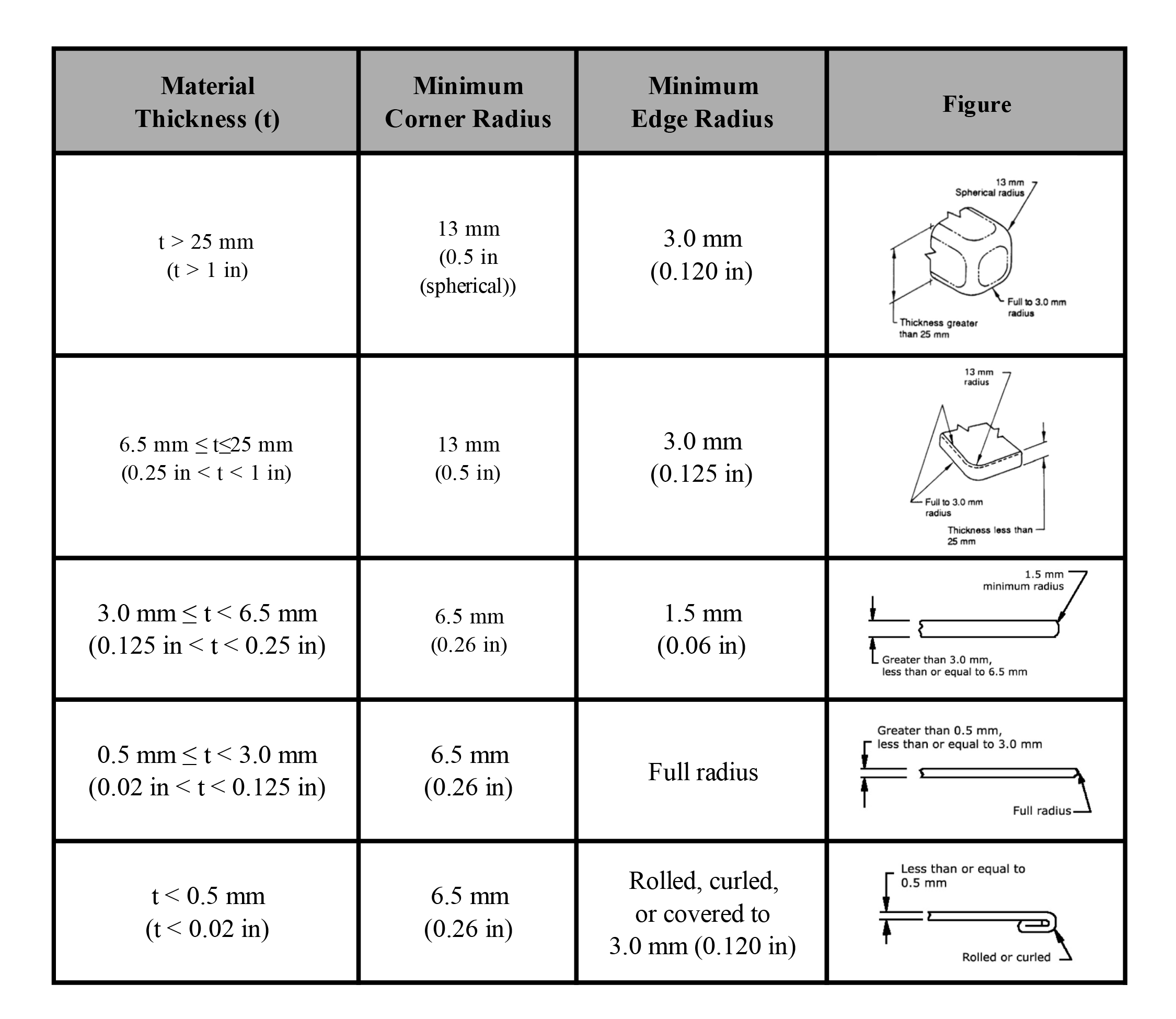
[V2 9009] Corners and edges of fixed and handheld equipment to which the bare skin of the crew could be exposed shall be rounded as specified in Table 9.3-1—Corners and Edges.
[Rationale: Sharp corners and edges in passageways, maintenance areas, stowage compartments, or workstations present hazardous conditions and are to be avoided. Also, handheld items such as tools present a hazard to the crew. In addition to potential hazards from IVA exposure, EVA exposure to sharp surfaces could damage suit integrity. This requirement applies to bare skin. Gloves and clothing may protect skin; however, some clothing or equipment items may be more vulnerable to tears and cuts. The crew may be exposed to items manufactured by a variety of companies, and this requirement is to be reflected in requirements for all of them.]
Table 9.3-1—Corners and Edges
9.3.1.7 Protection from Functionally Sharp Items
[V2 9010] Functionally sharp items shall be prevented from causing injury to the crew or damage to equipment when not in use.
[Rationale: Functionally sharp items are those that, by their function, do not meet the requirement for exposed corners and edges, e.g., syringes, scissors, and knives. These items are to be prevented from causing harm when not in nominal use. Capping sharp items is one way of doing this.]
9.3.1.8 Sharp Corners and Edges – Loose
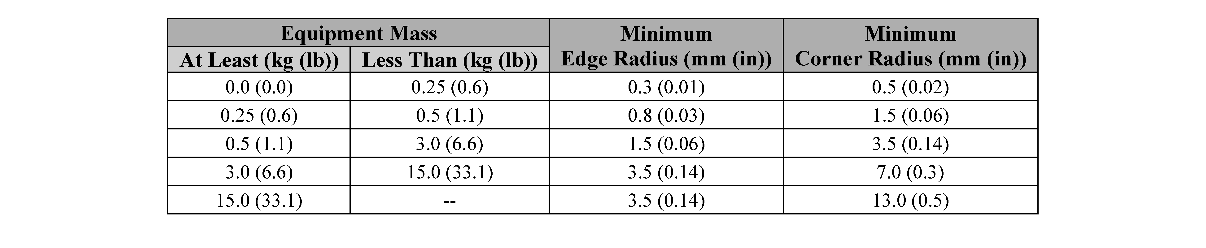
[V2 9011] Corners and edges of loose equipment to which the crew could be exposed shall be rounded to radii no less than those given in Table 9.3-2—Loose Equipment Corners and Edges.
[Rationale: The force (and resulting damage) in contact with fixed items depends on the mass and speed of the crewmember. The damage from loose items, however, depends on the weight of the item. For example, a person running into a fixed clipboard will cause more damage than if the clipboard were thrown at that person. Therefore, the corners and edges of a loose item do not have to be as rounded as a fixed item. Although hand-held items are loose, they are squeezed, and forces can be high. Therefore, hand-held items are to meet the edge and corner rounding requirements of fixed items as referenced in [V2 9009] Sharp Corners and Edges– Fixed, in this NASA Technical Standard.]
Table 9.3-2—Loose Equipment Corners and Edges
9.3.1.9 Burrs
[V2 9012] Exposed surfaces shall be free of burrs.
[Rationale: Burrs are manufacturing artifacts or can occur during a mission as a result of maintenance or assembly operations. Burrs cause damage to equipment and skin. They are to be removed as a part of the manufacturing process; or, if it is likely that they will be created during a mission, a means is to be provided to eliminate crew exposure to the burrs.]
9.3.1.10 Pinch Points
[V2 9013] Pinch points shall be covered or otherwise prevented from causing injury to the crew.
[Rationale: Pinch points can cause injury to the crew but may exist for the nominal function of equipment, i.e., equipment panels. This may be avoided by locating pinch points out of the reach of the crew or by providing guards to eliminate the potential to cause injury.]
9.3.1.11 Equipment Handling
[V2 9016] All items designed to be carried or removed and replaced shall have a means for grasping, handling, and carrying while wearing the most encumbering equipment and clothing anticipated.
[Rationale: Grasping, gripping, and moving hardware using hardware features that are not intended to be handles can damage the hardware or slip away and injure the crewmember or damage surrounding hardware. This can be prevented by designing obvious features that are intended for grasping, gripping, or moving the item. Manual Materials Handling (MMH) guidance can be used for identifying the appropriate MMH method based on equipment size, shape, weight (mass), gloved/ungloved, 1- or 2-person carry, etc. Pressurized and unpressurized suit biomechanics also needs to be considered for any tasks performed while suited as referenced in [V2 11024] Ability to Work in Suits, in this NASA Technical Standard.]
9.3.2 Temperature Exposure
The following temperature exposure requirements for bare skin [V2 9102] Skin/Tissue Damage Temperature Limits, and [V2 9103] Pain/Non-Disabling Injury Skin Temperature Limits, are summarized in Figure 9.3-1—Summary of Bare Skin Exposure Temperature Ranges, and Table 9.3-3—Summary Table of Bare Skin Exposure Temperature Ranges/Limits.
These temperatures are temperature limits for the outer layer of the skin. The calculation of the material being touched, in relation to its temperature and the contact time, will result in a skin temperature at the end of the contact period. This temperature must be compared to the values in Figure 9.3-1 to determine the need for control(s). Duration of skin contact with an object that is beyond the skin limits ensures the skin temperature is within the nominal range, may be used as a control. Refer to tables 9.3-(3-10) for equations and sample calculations for different materials that may be used to determine the duration of skin contact. Refer to ASTM C1057-17, Standard Practice for Determination of Skin Contact Temperature from heated surfaced using a mathematical model and thermesthesiometer.
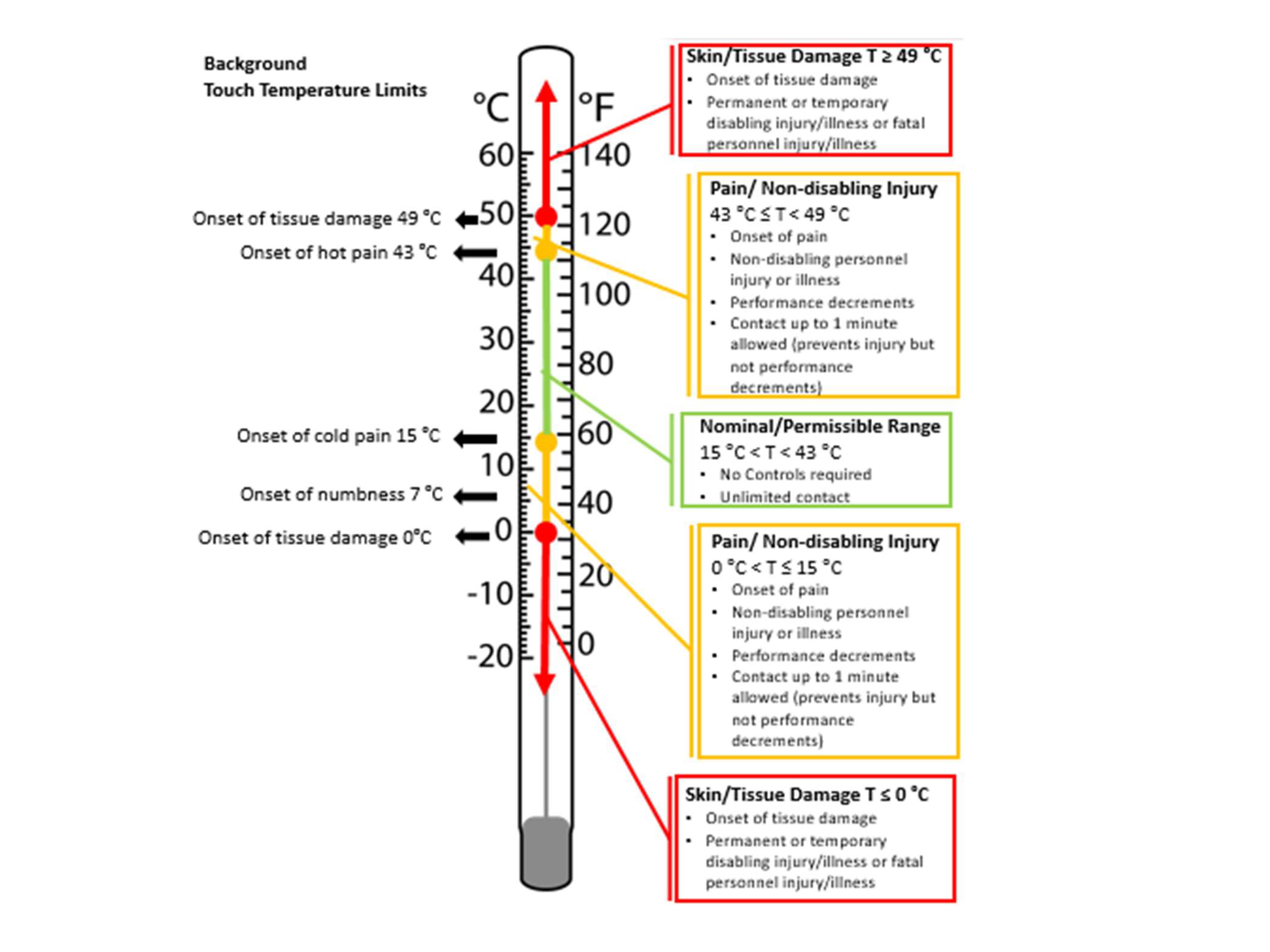
Figure 9.3-1—Summary of Bare Skin Exposure Temperature Ranges
Table 9.3-3—Summary Table of Bare Skin Exposure Temperature Ranges/Limits
| Nominal Thresholds (No Controls Required, Unlimited Contact) |
Sensation/Pain (Pain/Non-Disabling Injury/Possibly Resulting in Illness) [V2 9103] |
Skin/Tissue Damage (Controls required) [V2 9102] |
|---|---|---|
| 15°C < T skin < 43°C | 43°C ≤ T skin < 49°C or 0°C < T skin ≤ 15°C |
T skin ≥ 49°C or T skin ≤ 0°C |
9.3.2.1 Skin/Tissue Damage Temperature Limits
[V2 9102] Any surface to which the bare skin of the crew is exposed shall not cause skin temperature to exceed the injury limits in Table 9.3-4—Skin Temperature Injury Limits.
[Rationale: Skin Temperature Injury Limits are defined as any condition that may cause a permanent or temporary disabling injury/illness or fatal personnel injury/illness. For touch temperature, this condition was considered when tissue damage may be experienced. The following references were utilized to determine the limits: Hot: Greene, L.C., et al. (1958) on human tolerance to heat pain showed that the pain threshold is reached at 43.7ºC (110.7ºF) skin temperature. Lloyd-Smith, D.L., and Mendelssohn, K. (1948) found the pain threshold to be 44.6ºC (112.3ºF). Defrin, et al. (2006), found the pain threshold to be between 43-46ºC (109115ºF). Damage to porcine skin was determined to be at 49ºC (120.2ºF) (Moritz, et al., 1947). Hand dysfunction and the associated safety risk during occupational practices in the cold increases with decreasing skin temperature. Onset of cold pain has been reported to occur between 23°C (73.4ºF) and 14°C (57.2ºF) during cold contact (Havenith, et al., 1992). A marked deterioration in tactile discrimination occurs at finger skin temperatures <8ºC (46.4ºF) with numbness found in one-third of subjects at 7°C (44.6ºF) (Morton and Provins, 1960). Risk of frostbite occurs at 0 °C (32ºF) (Havenith, et al., 1992.). Time of skin exposure may be used as a control; this will depend on material and contact area and may be calculated using thermal models.]
Table 9.3-4—Skin Temperature Injury Limits
| Tissue Damage | Temperature Threshold Limit |
|---|---|
| High Temperature Limit | ≥ 49ºC |
| Low Temperature Limit | ≤ 0ºC |
9.3.2.2 Pain/Non-Disabling Injury Skin Temperature Limits
[V2 9103] Any surface to which the bare skin of the crew is exposed shall not cause skin temperature to enter the range for pain/injury in Table 9.3-5—Range for Pain/Non-Disabling Injury/Possibly Resulting in Illness.
[Rationale: Pain/Non-Disabling Injury Skin Temperature Limits are defined as any condition which may cause pain and performance decrements. The following references were utilized to determine the limits: Hot: Greene, L.C., et al. (1958) on human tolerance to heat pain showed that the pain threshold is reached at 43.7ºC (110.7ºF) skin temperature. Lloyd-Smith, D.L., and Mendelssohn, K. (1948) found the pain threshold to be 44.6ºC (112.3ºF). Defrin, et al. (2006), found the pain threshold to be between 43-46ºC (109-115ºF). Damage to porcine skin was determined to be at 49ºC (120.2ºF) (Studies of thermal injury ii. The relative importance of time and surface temperature in the causation of cutaneous burns *A. R. Moritz M.D., and F. C. Henriques, Jr., Ph.D. [From the Department of Legal Medicine, Harvard Medical School, Boston, Mass, 1946]. Cold Temperature Limit Values For Touching Cold Surfaces with the Fingertip [Q. Geng, et al., Ann. Occup. Hyg., Vol. 50, No. 8, pp. 851–862, 2006]). Hand dysfunction and the associated safety risk during occupational practices in the cold increases with decreasing skin temperature. Onset of cold pain has been reported to occur between 23°C (73.4ºF) and 14°C (57.2ºF) during cold contact (Havenith, et al., 1992). A marked deterioration in tactile discrimination occurs at finger skin temperatures <8ºC (46.4ºF) with numbness found in one-third of subjects at 7°C (44.6ºF) (Morton and Provins, 1960). Risk of frostbite occurs at 0°C (32ºF) (Havenith, et al., 1992).]
Table 9.3-5—Range for Pain/Non-Disabling Injury/Possibly Resulting in Illness
| Pain/Performance Decrements | Temperature Threshold Limit |
|---|---|
| High Temperature Range | 43°C ≤ Tskin < 49°C |
| Low Temperature Range | 0°C < T skin ≤ 15°C |
The following information is provided to aid designers in determining the duration of contact allowed for different materials before the skin exceeds the temperature limits.
The following tables and figures provide data and outline the methodology for determining the duration of contact time with an object, with respect to the skin temperature limits. In order to calculate the material thermal inertia, use documented thermophysical property resources. Table 9.3-6, Inverse Thermal Inertia for Commonly Used Materials, provides Inverse thermal Inertia for Commonly Used Materials. For high (43°C, 49°C) or low (0°C, 15°C) temperatures, use the subsequent figures (9.3-(2-5)) and tables (9.3-(6-10)) to determine the permissible material temperature (TPM) for the expected time of contact.
Table 9.3-6—Inverse Thermal Inertia for Commonly Used Materials
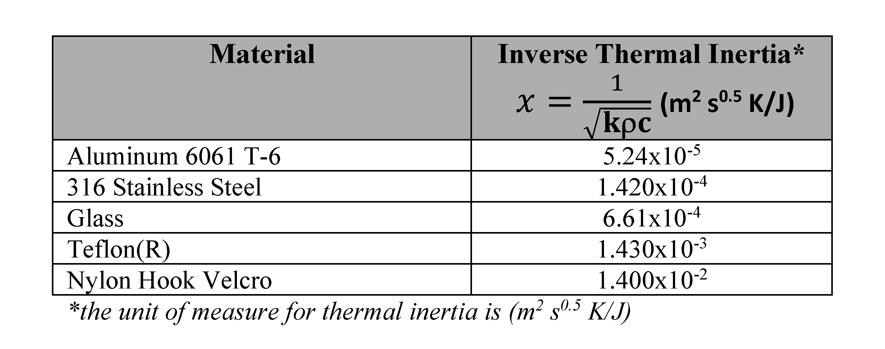

Table 9.3-7—High Temperature Constants: 49°C
| time (s) | a | b |
|---|---|---|
| 1 | 23,600 | 68.2 |
| 10 | 24,400 | 54.3 |
| 30 | 24,400 | 51.9 |
| 60 | 24,400 | 51.0 |
| ∞ | 24,400 | 49.6 |

Figure 9.3-2—High Temperature Tcat for Incidental and Intentional (Planned) Contact (49°C)
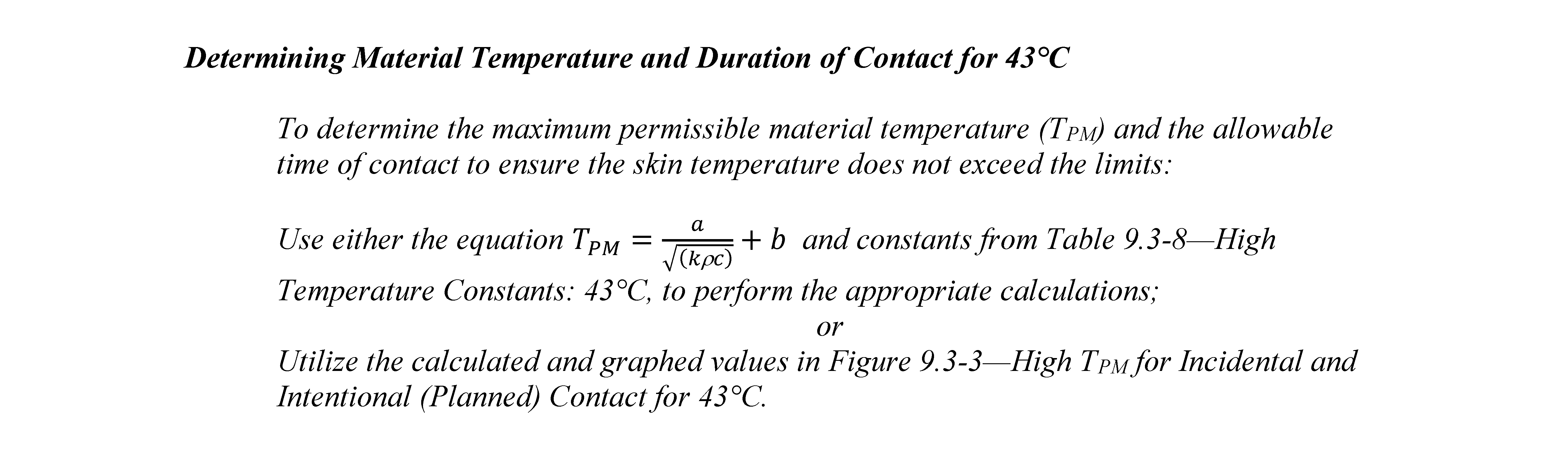
Table 9.3-8—High Temperature Constants: 43°C
| time (s) | a | b |
|---|---|---|
| 1 | 15,500 | 55.2 |
| 10 | 15,500 | 46.4 |
| 30 | 15,500 | 44.8 |
| 60 | 15,500 | 44.3 |
| ∞ | 15,500 | 43.4 |
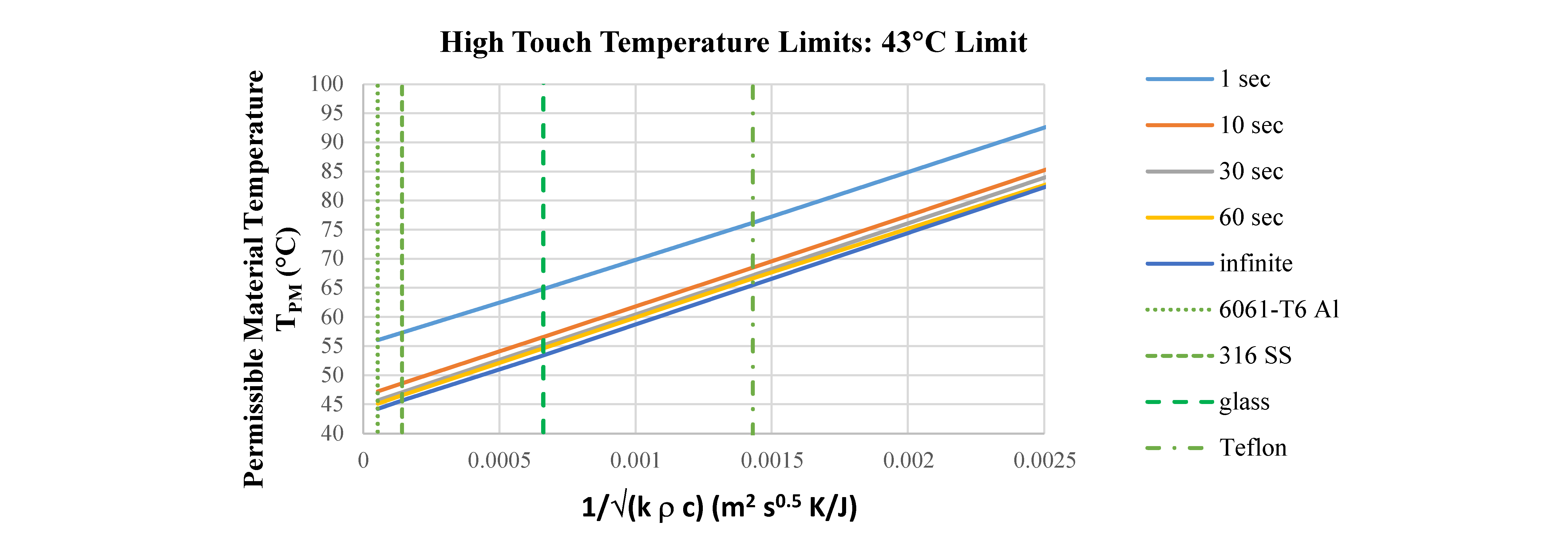
Figure 9.3-3—High TPM for Incidental and Intentional (Planned) Contact (43°C)

Table 9.3-9—Low Temperature Constants: 15°C
| time (s) | a | b |
|---|---|---|
| 1s for (k ρ c)0.5 < 2.324 x 10⁻⁴ |
-48,600 | 0 |
| 1s for (k ρ c)0.5 < 2.324 x 10⁻⁴ |
-23,800 | -5.77 |
| 10 | -22,700 | 15 |
| 30 | -16,400 | 15 |
| ∞ | -11,700 | 15 |
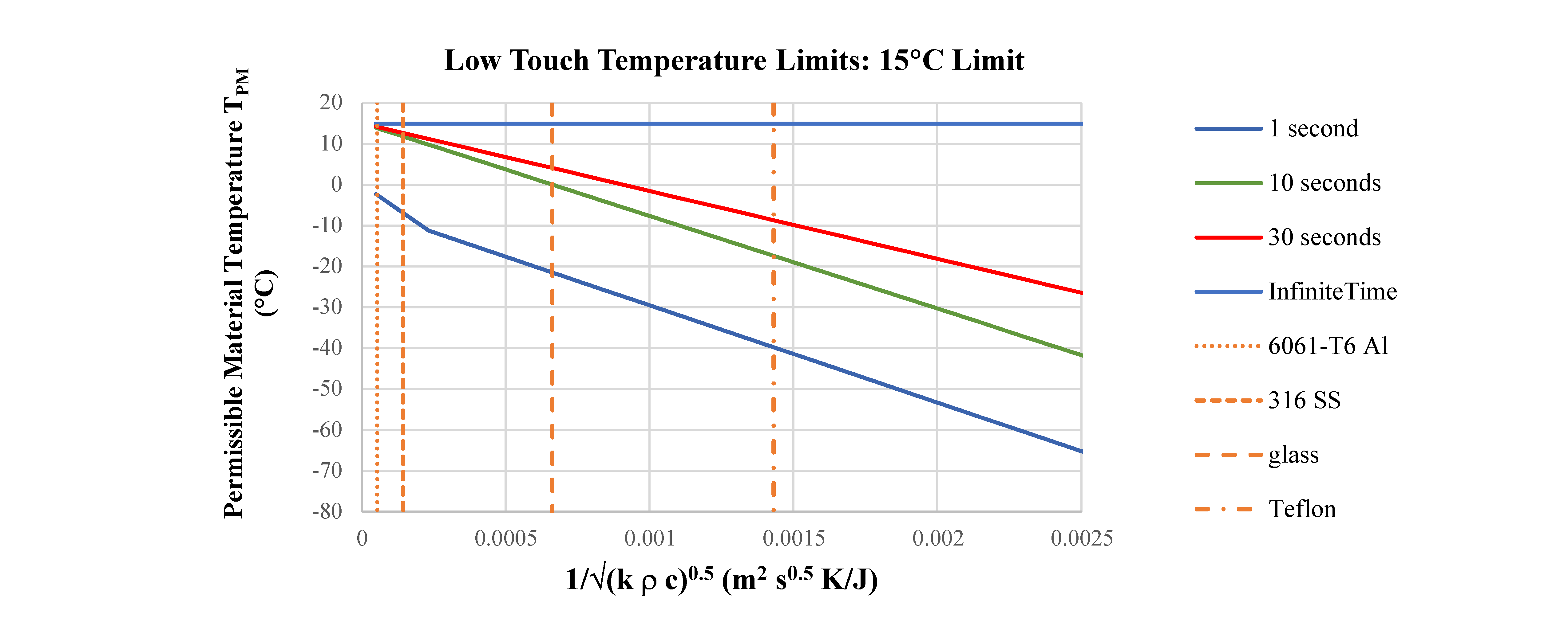
Figure 9.3-4—Low TPM for Incidental and Intentional (Planned) Contact (15°C)
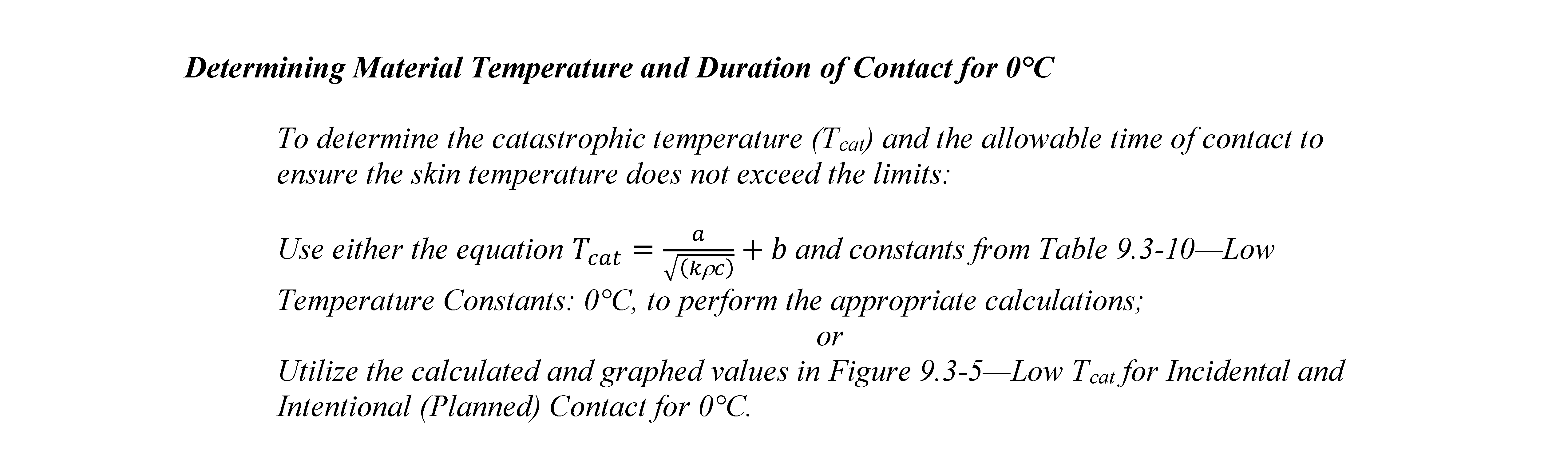
Table 9.3-10—Low Temperature Constants: 0°C
| times (s) | a | b |
|---|---|---|
| 1 | -48,600 | 0 |
| ∞ | -19,400 | 0 |

Figure 9.3-5—Low Tcat for Incidental and Intentional (Planned) Contact (0°C)
9.3.3 Electrical Shock Hazard Minimization
9.3.3.1 Power Interruption
[V2 9017] The system shall provide the crew with capability to control the power to an electrical circuit.
[Rationale: This assumes that, at some point in a mission, crew could come in contact with exposed conductors which could cause electrical shock or arcing and/or molten metal resulting in crew injury/death or equipment damage. Thus, there must be a way for the crew to eliminate this exposure by interrupting power, as opposed to only remote control.]
9.3.3.2 Energized Status
[V2 9018] The system shall provide and display the de-energized status (interruption of electrical power) of a circuit to the crew and within their fields of regard.
[Rationale: When de-energizing a system, the user must always be provided with feedback that confirms the function has occurred. For efficiency, the display is to be visible to the crew without having to move from their position. Because of the critical nature of this information, the complexity of some circuits, and the possibility of a false indication, many times circuit status is verified using a separate tool such as an electromagnetic sensor.]
9.3.3.3 Nominal Physiological Electrical Current Limits
[V2 9019] Under nominal situations (routine human contacts to conductive housing), the program shall limit electrical current through the crewmember to ≤ (less than or equal to) 0.4 mA for Direct Current (DC) and ≤ (less than or equal to) 0.2 mA peak for Alternating Current (AC).
[Rationale: These values are below the physiological effect of sensation for the most sensitive members of the astronaut population. This requirement is intended to address typical exposure situations where human contact can routinely occur with conductive housing of electrical equipment, and in these situations no perceptible current flow is the design requirement. Typically, NASA engineering teams establish 1 MΩ (Megaohm) isolation along with grounding to conductive surfaces with Class H or better bond to prevent current flow through crewmembers.]
9.3.3.4 Catastrophic Physiological Electrical Current Limits
The following two requirements set the physiological electrical current limits used in hazard analysis (for all circumstances, [V2 9020] Catastrophic Physiological Electrical Current Limits for all Circumstances, and specifically for unique circumstances where startle reaction may cause a catastrophic event, [V2 9021] Catastrophic Physiological Electrical Current Limits for Startle Reaction), for determining hazard severity, failure tolerance, and controls of a system that could pose a catastrophic electrical shock to the human. These thresholds are used when a hazard analysis is considering failure scenarios and off nominal events where failures such as electrical short circuits have compromised system isolation and pose a risk of catastrophic electrical shock to the human.
9.3.3.4.1 Catastrophic Physiological Electrical Current Limits for all Circumstances
[V2 9020] The program shall limit the electrical current through the crewmember to ≤ (less than or equal to) 40mA for DC and ≤ (less than or equal to) 8 mA peak for AC to avoid catastrophic physiological effects to the crewmember.
[Rationale: International Electrotechnical Commission (IEC) is the leading global organization that prepares and publishes international standards for all electrical, electronic, and related technologies. The limits for current that could pass through a crewmember were chosen based on the threshold for maintaining muscle control if shocked to protect 99.5% of the population (IEC 60479-2, Effect of current on human beings and livestock, Part 2: Special aspects, Figure 7). This NASA Technical Standard is intended to provide the threshold where additional engineering controls will be required to mitigate the catastrophic nature of electrical shock/physiological effects to the human.
For the above current limits, utilizing the worst-case body impedance of 850 Ω (Ohms) the maximum DC voltage would be 34 volts and the maximum AC voltage would be 6.8 volts. The 850 Ω (Ohms) represents the 5th percentile of the population for a touch voltage of 125 volts and a large contact area (such as full hand or a surface area of 82 cm2) in saltwater-wet conditions (IEC 60479-1, Effects of current on human beings and livestock, Part 1: General Aspects, Table 3). Higher body impedances, and thereby higher voltages, may be allowed based on a case-by-case analysis (contact area, wet conditions etc.) utilizing 5% body impedances tables in IEC 60479-1, and with the approval by the appropriate Safety Panel.]
Note: AC limit is for 50/60 Hz. If different frequencies are required, refer to IEC 60479-2, Figure 2. For different waveshapes and AC/DC combinations, refer to IEC 60479-2 limits. For voltage spikes of short duration (<1 second), refer to IEC TR 60479-5, Effects of current on human beings and livestock, Part 5: Touch voltage threshold values for physiological effects, for limits (Figure 5, curve c1 for AC and Figure 14, curve c1 for DC).
9.3.3.4.2 Catastrophic Physiological Electrical Current Limits for Startle Reaction
[V2 9021] During critical operations where a startle reaction is possible, the program shall limit electrical current through the crewmember to ≤ (less than or equal to) 2 mA for DC and ≤ (less than or equal to) 0.5 mA for AC to avoid potentially catastrophic conditions.
[Rationale: IEC is the leading global organization that prepares and publishes international standards for all electrical, electronic, and related technologies. The current values were chosen based on the threshold for a startle reaction if shocked (IEC TR 60479-5, Effects of current on human beings and livestock, Part 5: Touch voltage threshold values for physiological effects, Table 1). Under certain circumstances such as startle reaction, more restrictive thresholds than the physiological catastrophic limits ([V2 9020] Catastrophic Physiological Electrical Current Limits for all Circumstances) may be employed in hazard and risk assessments. Consider the terrestrial examples of involuntary reaction and let go thresholds.
For a person at rest in a chair not performing a critical task, these exposures are not catastrophic. However, consider an electrician on a ladder or the pilot of an aircraft where splitsecond involuntary reactions can have dire consequences where the threshold of safety must be set lower at the startle reaction electrical current values. The application of these lower thresholds would be case-by-case in unique circumstances where it is deemed appropriate, such as during manual control of a spacecraft or during EVA. For the above current limits, utilizing the worst-case body impedance of 850 Ω (Ohms), the maximum DC voltage would be 1.7 volts and the maximum AC voltage would be 0.4 volts. The 850 Ω (Ohms) represents the 5th percentile of the population for a touch voltage of 125 volts and a large contact area (such as full hand or a surface area of 82 cm2) in saltwater-wet conditions (IEC 60479-1, Effects of current on human beings and livestock, Part 1: General Aspects, Table 3). Higher body impedances, and, thereby, higher voltages, may be allowed based on a case-by-case analysis (contact area, wet conditions, etc.) utilizing 5% body impedances tables in IEC 60479-1 and with the approval by the appropriate Safety Panel.
Note: AC voltage is for 50/60 Hz. If different frequencies are required, refer to IEC 60479-2, Effect of current on human beings and livestock, Part 2: Special aspects, Figure 2. For different wave shapes and AC/DC combinations, refer to IEC 60479-2 limits.]
9.3.3.5 Body Impedance for Voltage Calculations Utilizing Electrical Current Thresholds
[V2 9022] The program/project shall use the 5th percentile values for the appropriate conditions (wet/dry, AC/DC, voltage level, large/small contact area) from IEC 60479-1, Effects of current on human beings and livestock – Part 1: General Aspects, to determine the appropriate body impedance to calculate the voltage associated with any current limit analysis.
[Rationale: IEC is the leading global organization that prepares and publishes international standards for all electrical, electronic, and related technologies. For example, 850 Ω (Ohm) represents the 5th percentile of the population for a touch voltage of 125 volts and a large contact area (such as full hand or a surface area of 82 cm2) in saltwater-wet conditions (IEC 60479-1, Table 3). Higher body impedances and, thereby, higher voltages, may be allowed based on a case-by-case analysis utilizing 5% body impedances tables with the approval of the program’s Safety Panel. Higher body impedances and, thereby, higher voltages, may be allowed based on a case-by-case analysis utilizing 5% body impedances tables with the approval of the program’s Safety Panel.]
9.3.3.6 Leakage Currents – Medical and Bioinstrumentation Equipment
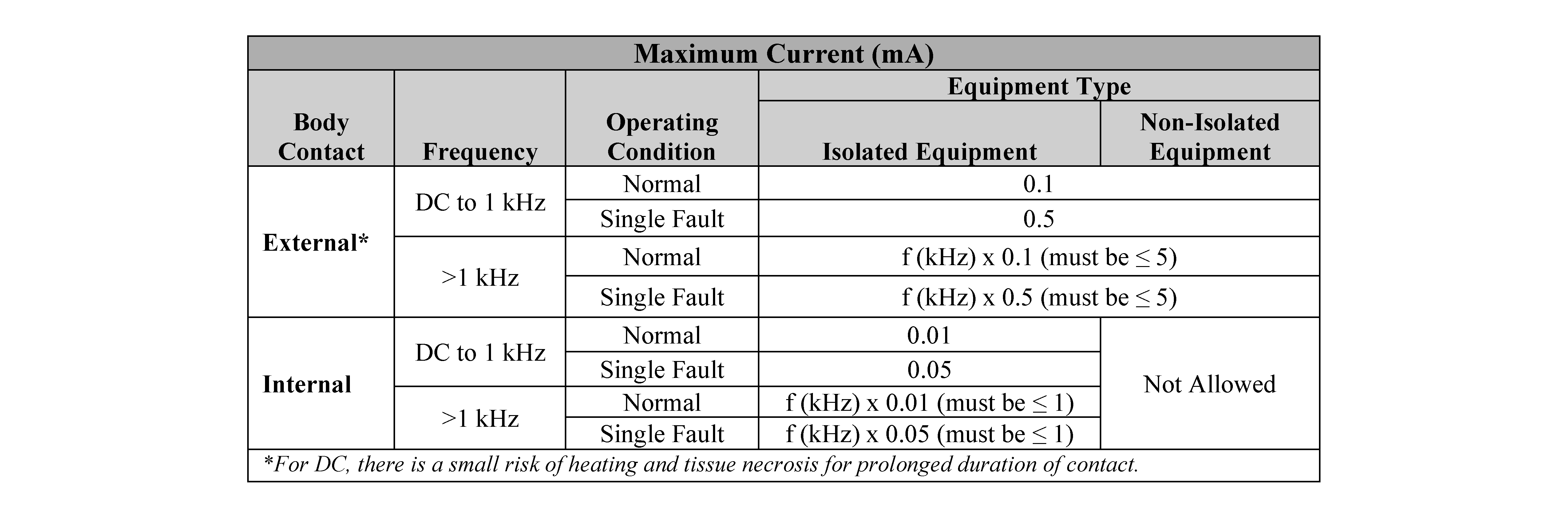
[V2 9023] For equipment such as bioinstrumentation and medical devices, that are specifically designed to contact the human body, electrical leakage currents caused by contact with exposed surfaces (including in worst-case fault scenarios) shall be kept below the levels specified in Table 9.3-11—Leakage Currents-Medical and Bioinstrumentation Equipment.
[Rationale: Some equipment needs to pass small amounts of current through the body to accomplish its intended function, e.g., bias currents in medical monitoring equipment. The amount of current allowed depends on the frequency and whether the part of the equipment contacting the crewmember is isolated from the power source. Examples of isolated equipment are intra-aortic catheters and electrocardiogram (ECG) monitors. Examples of non-isolated equipment are blood pressure cuffs and digital thermometers. These levels of leakage current are consistent with those in IEC 60601-1, Medical Electrical Equipment – Part 1: General Requirements for Basic Safety and Essential Performance, for patient auxiliary and patient leakage currents in isolated (type CF) and non-isolated (types B and BF) equipment. These leakage currents are measured across parts applied to the crewmember and from the applied parts to ground. The summation of all the currents must be compared to the current limits in Table 9.3-11. Architectural contributions, such as an independent current monitor with interlock, can prevent dangerous currents in the case of equipment fault scenarios.]
Table 9.3-11—Leakage Currents – Medical and Bioinstrumentation Equipment
9.3.4 Fluid and Gas Spill Hazard Minimization
9.3.4.1 Fluid/Gas Release
[V2 9024] Hardware and equipment shall not release stored fluids or gases in a manner that causes injury to the crew.
[Rationale: Crew injuries are likely to be caused by either highly pressurized fluids and gases or toxic fluids and gases. In both cases, design requirements are to be developed so that the crew is protected during both storage and handling of these fluids and gases.]
9.3.4.2 Fluid/Gas Isolation
[V2 9025] The system shall provide for the isolation or shutoff of fluids in hardware and equipment.
[Rationale: Fluids are most likely to be temporarily shut off at service and maintenance points. System developers are to identify those points and create isolation capabilities. Without dedicated isolation controls, crews could create bypasses, which waste crew time and possibly damage systems. Also, to save time and reduce the possibilities of error, e.g., forgetting to shut them off or to turn them back on when maintenance is complete, the shut-off valves are to be located near those service points and operable while wearing the most encumbering equipment and clothing anticipated.
Note: The term fluid includes both liquid as well as gas.]
9.3.4.3 Fluid/Gas Containment
[V2 9026] The system shall provide for containment and disposal of fluids that might be released during operation or maintenance.
[Rationale: Excess fluids are likely to be released during draining and filling of systems. Designs are to accommodate these possibilities to ensure free fluid control, collection, containment, or disposal that is safe and effective. Some examples of control, collection, and disposal methods include fluid-sealed connectors, volume sensors, flow sensors, overflow valves, accumulators, vacuum systems, and system waste venting. Collection and containment facilities are to be located near the points where release is likely to occur (maintenance or service points). Control of unexpected gas and fluid release due to system or component failure are to be assessed by safety hazard analysis. This requirement applies to fluids under the system’s control.]
9.4 Durability
9.4.1 Equipment Protection
[V2 9027] Systems, hardware, and equipment shall be protected from and be capable of withstanding forces imposed intentionally or unintentionally by the crew.
[Rationale: Unintentional damage can occur if items are in a location where crew is focused on other activities such as translation, moving equipment, or maintaining other systems. Designers are to identify areas of crew activity and decide if exposed hardware and equipment are sufficiently durable for unintended forces. Such hardware and equipment may have to be relocated, guarded, covered, e.g., with close-out panels, or simply designed to be more durable. “Intentional” damage may result from crewmembers securing or tightening items (latches, retainers, bolts, screws, etc.) using forces beyond their design limits. This often occurs under panic conditions. Hardware designers are to use crew strength data and to assume the crew could apply their maximum strength forces.]
9.4.2 Isolation of Crew from Spacecraft Equipment
[V2 9028] Protective provisions, e.g., close-out panels, shall be provided to isolate and separate equipment from the crew within the habitable volume.
[Rationale: Protective provisions such as closeout panels serve the following functions: provide protection from forces in accordance with [V2 9027] Equipment Protection, in this NASA Technical Standard; provide fire abatement protection and isolation and support of fire extinguishing operations; protect crew from ignition sources and sharp edges and retain debris from coming out into habitable volume; protect equipment from ground or flight crew operations; provide acoustic barrier for noise generated behind panels; minimize snag potential; and prevent loose items or equipment from becoming lost. In addition, protective provisions are designed to provide a smooth surface, faired-in with the adjacent crew compartment structure, and be compatible with crew passageway requirements.]
9.5 Assembly and Disassembly
9.5.1 Hardware and Equipment Mounting and Installation
[V2 9029] System hardware and equipment shall be designed so that it cannot be mounted or installed improperly.
[Rationale: Ideally, similar items are interchangeable. The preferred method of preventing improper installation and mating is a design that prevents it such as misaligned mounting holes, pins, or keys. The designs to prevent installation and mating errors are to be rugged enough to withstand persistent attempts. Cues (such as color or labeling) can be provided to remind crewmembers, so they save the time of trying to make improper installations. However, these cues are not to be the sole countermeasure to improper installation and mating.]
9.5.2 Mating and Demating
9.5.2.1 Connector Spacing
[V2 9030] The spacing between connectors shall permit mating and demating by crewmembers wearing expected clothing.
[Rationale: Adequate access and working space allows personnel to efficiently access equipment in a way that allows nominal and off-nominal tasks to be performed. Access to connectors may be required during equipment assembly, reconfiguration, or maintenance. Access and work envelopes are different for differing tasks. In particular, protective garments, e.g., spacesuits, may be required by the flight crew and are to be accommodated.]
9.5.2.2 Connector Actuation without Tools
[V2 9031] Connectors shall be operable without tools for mating and demating while wearing the most encumbering equipment and clothing anticipated.
[Rationale: Connector actuation includes mating/connecting and demating/disconnecting of a connection. Lost or damaged tools prevent connectors from being connected or disconnected, which may result in loss of crew (LOC) or loss of mission (LOM).]
9.5.2.3 Incorrect Mating, Demating Prevention
[V2 9032] Cable, gas and fluid lines, and electrical umbilical connectors shall prevent potential mismating and damage associated with mating or demating tasks.
[Rationale: Ideally, similar items are interchangeable. The preferred method of preventing improper installation and mating is a design that prevents it such as misaligned mounting holes, pins, or keys. The designs to prevent installation and mating errors are to be rugged enough to withstand persistent attempts. Cues (such as color or labeling) can be provided to remind crewmembers, so they save the time of trying to make improper installations. However, these cues are not to be the sole countermeasure to improper installation and mating.]
9.5.2.4 Mating, Demating Hazards
[V2 9033] The system shall not subject personnel and equipment to hazards, including spills, electrical shocks, and the release of stored energy, during mating or demating.
[Rationale: Maintenance or service tasks are not likely to be familiar, and thus crews may be more focused on these tasks. Hazards that would normally be identified and avoided may go unnoticed during maintenance. Design requirements and solutions are to identify hazards that are exposed during maintenance activities and determine ways to eliminate these hazards or protect the crew from them.]
9.6 Cable Management
9.6.1 Cable Management
[V2 9034] The system shall manage cable, wire, and hose location, protection, routing, and retention to prevent physical interference with crew operations and safety.
[Rationale: Designers are to define areas of activity and route fixed lines and cables so that they are both protected and also do not interfere with these activities. Pressurized lines and hoses must be restrained to prevent crew injury. Also, system designers are to focus on non-fixed lines and cables that may be unstowed or moved for a specific task or temporary rearrangement. While the rerouted cable or line may accommodate a specific need, the routing path may interfere with other, non-related activities such as crew translation and egress. Designers are to identify potential uses for lines and cables and ensure the start points, end points, and cable and line routes in between accommodate all crew activities.]
9.7 Design for Maintainability
Maintenance constitutes a large portion of a system lifecycle, and it can consume a significant amount of time during a mission. Designing for maintainability involves system level optimization for parts, analyzing the resulting ergonomics, and considering tools and information as part of the design.
9.7.1 General
9.7.1.1 Maintenance Concept of Operations
[V2 9111] For each maintenance-level item, the human spaceflight program shall define and document a maintenance operational concept considering the following factors, as a minimum, and updated throughout the design lifecycle:
- Mission work natural environment (e.g., dust, lighting, heating, atmosphere, gravity)as specified in program requirements for natural environments (e.g., SLS-SPEC-159 Cross Program Design Specification for Natural Environments (DSNE)).
- Tools, aids, and support equipment available to the maintainers in-situ.
- Skill-level of the maintainers (i.e., crewmembers).
- Access needed to equipment – considering mission-criticality, urgency of repair, anticipated frequency of servicing, and complexity of approach.
- Reliability- or performance-driven preventive maintenance schedule.
- Preventive and corrective maintenance plans.
- Total crew time and number of crew needed.
[Rationale: Maintenance level items are assembled units or modules that are designed to be isolated from the rest of its system, removed, maintained, repaired, and/or replaced by the maintainer on-mission. Certain subsystems are so crucial to survival they need to be identified to drive modularity and sparing of the entire system. Maintenance-level items and subsystems are identified through the trade space analysis considering the following factors, among others: reliability, redundancy, functionality sustainment, stress reduction, derating, accessibility, modularity, and condition-based monitoring. If proper attention and emphasis is not placed on supportability concerns and issues, particularly early in a program, then the potential undesired impacts to operations can be significant. NASA has been able to shift maintainability requirements from design phase to operations because ground support can be increased throughout the mission. This will not be possible to the same extent with longer lunar surface operations where vehicles and equipment will reside on the Moon. The same will be true for Mars compounded by long communication latencies that will not allow ground to provide realtime guidance and oversight for preventive and corrective maintenance tasks. In addition, environmental factors associated with surface operations, including dust, thermal extremes, day to night transitions, static electricity, dormancy, etc., will increase maintainability challenges. Standards and requirements for supportability, must be implemented early in missions beyond low-Earth orbit utilizing technologies that cannot be repaired on Earth and cannot be replaced from Earth. Impacts of not developing a Maintenance ConOps include loss of a mission or loss of life given the communication latencies, resupply challenges and evacuation constraints of NASA’s long-duration missions (e.g., Lunar and Martian DRMs).]
9.7.1.2 Availability of Critical Systems
[V2 9112] System repairs and/or replacements shall be designed to be completed within the time-to-effect margin.
[Rationale: Mission success is dependent on the availability of the critical systems that keep the crew safe and enable completion of mission objectives. System reliability is one approach to assuring availability. If reliability cannot be guaranteed, corrective maintenance and contingency plans are needed to assure system operation. System availability requirements may be time constrained depending on system availability requirements. Operational factors, including available onboard resources, crew capabilities, and environmental constraints, affect the design and feasibility of corrective maintenance activities. If repairs/replacements cannot be completed in within the time-to-effect margin (NASA, 2021; Kennedy Space Center Office of Mission Assurance, 2015), alternative design strategies (e.g., redundancy) need to be utilized to maintain critical functionality.]
9.7.1.3 Damage Prevention
[V2 9113] The system shall be designed to prevent damage during maintenance.
[Rationale: Maintenance activities can lead to increased failures because there is risk to the subject system and proximate systems each time the system is opened or disturbed, especially when systems are not designed for maintainability. Designing the system to the physical capabilities and limitations of the maintainer (e.g., ensuring parts are accessible by hand) prevents collateral and inherent damage when proper procedures are followed. Designing systems to contain failure effects, minimize failure propagation, and minimize interaction with proximate systems also reduces the risk of collateral damage during maintenance. Designs and maintenance strategies are to be analyzed (e.g., failure/process analysis) for feasibility and risk prior to incorporation.]
9.7.1.4 In-Mission Maintenance
[V2 9114] The program shall design all flight hardware and software to facilitate in-mission preventive and corrective maintenance and check-out.
[Rationale: Crew and vehicle health and the ability to meet mission objectives require that maintenance and check-out activities be achieved with efficiency and accuracy. Design considerations, e.g., tool interfaces, can significantly impact the performance of these activities. Maintainability and its characteristics are to be considered in the design trade space.]
9.7.1.5 Design for Maintenance
[V2 9036] The system shall provide the means necessary for the crew to safely and efficiently perform routine service, maintenance, and anticipated unscheduled maintenance activities while wearing the most encumbering equipment and clothing anticipated.
[Rationale: Reduction in the time devoted to maintenance and servicing can mean more crew time devoted to achieving mission goals. Also, because of the complexity of space missions and the interdependency of many factors (equipment, supplies, weather, solar flares, political considerations, etc.), designs are to minimize reliance on outside maintenance support. Designs are to provide the tools, parts, supplies, training, and documentation necessary for crews to maintain efficient and safe operations.]
9.7.1.6 Commercial Off-the-Shelf (COTS) Equipment Maintenance
[V2 9037] Maintenance for commercial off-the-shelf equipment shall be suitable to the spaceflight environment.
[Rationale: Systems designed for terrestrial environments may be adapted for space missions. This adaptation is to include procedures and features that will allow maintenance tasks to be performed safely and effectively in a space mission environment. Major changes that likely need accommodation are differences in gravity or crewmembers wearing gloves.]
9.7.2 Tools and Test Equipment
9.7.2.1 In-Mission Tool Set
[V2 9038] The program shall establish a common set of in-mission tools and test equipment for spaceflight and surface systems.
[Rationale: Establishing a common set of tools with which all mission systems can be maintained minimizes mass and complexity, reduces training demands, and increases redundancy for a given mission. Tool set design is to be based partly on reducing the demands on the crew: selecting tools that are likely to be familiar to crewmembers and minimizing the number of different tools. IVA and EVA tools generally differ due to the unique requirements imposed by the EVA environment, therefore a common set of IVA and a common set of EVA tools with as much overlap as possible is a primary goal of this requirement. The other primary goal of this requirement is to have a common set of tools for all phases of the mission to be used across all elements of the mission (e.g., transportation vehicle, orbital outpost, lander, surface habitat, and surface systems should all use the same common toolkit). Apollo and ISS lessons learned indicate that tool set design is also to consider the complement of tools and equipment needed to respond to unexpected failures and hardware workarounds. Having a comprehensive and common tool set is especially important for future long-duration missions with constrained or nonexistent resupply operations.]
9.7.2.2 Maintenance Tools Usability
[V2 9115] Tools and test equipment shall be usable by the full range of crew sizes and strengths wearing any personal protective equipment (PPE).
[Rationale: Crew members of varying size and strength need the capability to conduct maintenance activities under a variety of conditions. Ensuring tools and test equipment are usable under the most encumbering circumstances reduces maintenance time and complexity.]
9.7.2.3 Tool and Test Equipment Commonality
[V2 9116] Systems and units of equipment shall be designed so that maintenance can be accomplished with the set of in-mission tools and test equipment.
[Rationale: ISS lessons learned indicate that crews often have difficulty locating the tools and test equipment needed for a given activity, resulting in many hours spent searching for items and delayed maintenance. Tool and test equipment commonality provides redundancy and contributes to crew readiness for unplanned maintenance activities. Interchangeable tools and test equipment improve mass efficiency because common items can cover multiple types of failures. Utilizing common tools and test equipment across vendors increases in importance for missions beyond low-Earth orbit when increasingly complex and limited resupply operations constrain the ability to replace missing or ineffective tools and test equipment while simultaneously limiting the ability to return maintenance items (MIs) to the ground for maintenance. Commonality helps to ensure the right tools and test equipment are available at the right time to crewmembers in-mission.]
9.7.2.4 Tool Clearance
[V2 9050] The system shall provide tool clearances for tool installation and actuation for all tool interfaces during in-mission maintenance.
[Rationale: Tools to be used for in-mission maintenance are to be identified by the hardware developer, and clearance for application is to be accommodated to ensure that maintenance tasks can be performed.]
9.7.3 Maintenance Efficiency
9.7.3.1 Maintenance Time
[V2 9039] Planned maintenance for systems and associated hardware and equipment shall be capable of being performed within the allotted crew schedule while wearing the most encumbering equipment and clothing anticipated.
[Rationale: Maintenance and servicing are directly related to the amount of time available for mission goals. Reduction in the time devoted to maintenance and servicing means more crew time devoted to achieving mission goals. Also, because of the complexity of space missions and the interdependency of many factors (equipment, supplies, weather, solar flares, changes in mission design and objectives, etc.), designs are to be self-sufficient and minimize reliance on outside maintenance support. Designs are to provide the tools and mechanisms (including cleaning), parts (as modular units where possible), supplies, training, and documentation necessary for crews to maintain efficient and safe operations. Crew schedule allotted for planned maintenance is to include time associated with dust management and cleaning.]
9.7.3.2 Captive Fasteners
[V2 9042] Fasteners used by the crew during maintenance shall be captive.
[Rationale: Freed fasteners become Foreign Object Debris (FOD) in microgravity, which pose a risk during the mission. Fasteners can be lost either by loosening during normal use or by becoming misplaced during maintenance operations. Space missions are generally isolated, and replacement parts are not available. This is particularly important in zero gravity environments because small items such as fasteners can be very difficult to find.]
9.7.3.3 Minimum Number of Fasteners – Item
[V2 9043] For items that may be serviceable by the crew, the number of fasteners used shall be the minimum required to meet structural engineering integrity requirements.
[Rationale: Designers can add a safety factor to some configurations by increasing the number of fasteners. However, when crews are to routinely remove the fasteners, selection of the number of fasteners is also to consider reduction of crew time devoted to maintenance activities.]
9.7.3.4 Minimum Variety of Fasteners – System
[V2 9044] The system shall be serviceable with a common set of fasteners that meet structural integrity requirements.
[Rationale: Different fasteners require different tools and procedures for removal and replacement. Commonality of fasteners can reduce times to access and the need for different tools. It can also reduce training times necessary to introduce crews to the fastener types.]
9.7.4 Accessibility
9.7.4.1 Access Using Available Tools
[V2 9117] Systems and units of equipment that require maintenance shall be accessible and openable during the mission using the on-board tool set.
[Rationale: Accessibility is a key characteristic of system maintainability, and therefore to system availability. Even if the equipment does not require preventive maintenance, or is not anticipated, due to reliability estimates, to require corrective maintenance, it may need to be accessed and opened due to unforeseen events. Further, logistical constraints of missions beyond LEO will require maintenance to be performed at an intermediate level—e.g., that below the maintenance item (MI) level. ISS experience has shown that intermediate level maintenance is problematic if not all parts of the MI are designed to be accessed or repaired (Bertels, 2006). As sparing will be limited during extended missions without access to frequent resupply, it may also be necessary to scavenge parts from operating equipment to replace failed parts in higher priority systems. System designers consider the physical capabilities of crewmembers and the factors of the environment (e.g., limited gravity, physical space) when assessing accessibility.]
9.7.4.2 Maintenance Item Location
[V2 9045] The system shall ensure maintenance access to the items prioritized [V2 9111] Maintenance Concept of Operations, so that the maintenance task does not require the removal or disabling of other systems or components (excluding access panels).
[Rationale: Location of items depends on many factors (physical room, interface with other items, manufacturing considerations, etc.), and maintenance can be easily overlooked. It is important, therefore, that, early in a design, system developers identify those items that will require frequent and/or critical maintenance. Accessibility to critical items and those items requiring frequent servicing is a priority. Deintegrating and demating is a source of risk during maintenance. Required electrical and pressure and fluid system safing are exempt from this requirement. Requirement to be verified using maintenance task analysis.]
9.7.4.3 Check and Service Point Accessibility
[V2 9046] Check points and service points for systems, hardware, and equipment shall be directly accessible while wearing the most encumbering equipment and clothing anticipated.
[Rationale: System designs are to support mission goals that do not normally devote crew time to maintenance tasks. Removal of items to access check and service points increases maintenance times. Also, complex and time-intensive maintenance procedures could discourage performance of scheduled tasks.]
9.7.4.4 Maintenance Accommodation
[V2 9047] Physical work access envelopes shall accommodate the crew, required tools, and any protective equipment needed to perform maintenance.
[Rationale: Maintenance tasks are to be defined and analyzed with worst-case assumptions. Volume is to be provided to allow the size extremes in the crewmembers performing the tasks using proper tools and protective equipment within the prescribed times. Hand clearance for inflight maintenance tasks is to be provided by the hardware developer to ensure that maintenance tasks can be performed while wearing the most encumbering equipment and clothing anticipated.]
9.7.4.5 Visual Access for Maintenance
[V2 9048] Maintenance tasks that require visual feedback shall be directly visible during task performance while wearing the most encumbering equipment and clothing anticipated.
[Rationale: Efficient and safe performance of many maintenance tasks requires vision during task performance. In crowded spaces, hands and tools can block vision of the task. On those tasks that require vision during task performance (such as alignments or adjustments), designers are to locate and design equipment to provide this vision.]
9.7.5 Visibility and Identifiability
9.7.5.1 Component Identification
[V2 9118] Flight systems shall include information and labeling that enables the crew to correctly locate, handle, and identify the systems components.
[Rationale: When beginning a maintenance activity, crewmembers often spend time up-front locating, identifying, and familiarizing themselves with the components. Clear and informative labeling can streamline this process, and help crew properly contextualize the component within the larger system. Unique identifications that enable rapid recognition among similar items reduce maintenance time. Consistency in the manner of identification across items decreases the time needed for locating and interpreting identifications. Identifications that enable rapid recognition without the use of conversion tables are less susceptible to errors. Redundant identifications give maintainers more than one opportunity to identify the item, increasing maintenance efficiency. It is important to provide an accurate representation of the interior of any flight hardware unit that can be opened, both to ensure crew safety and to prevent damage to the system. Refer to [V2 10151] Labeling Plan and Icon Library for guidance on labeling, as well as label specifications found in Appendix F.5.2. A program-wide labeling plan and icon library are to specify and document characteristics of the labels and icons used in human interface. Additional design standards for cables, wires, and harnesses can be found in NASASTD-8739.4 Workmanship Standard for Crimping, Interconnecting Cables, Harnesses, and Wiring.]
9.7.5.2 Cable Identification
[V2 9035] All maintainable cables, wires, and hoses shall be uniquely and consistently identified at the maintenance point.
[Rationale: Locating and identifying the specific cable, wire, or hose needed for a maintenance activity can be time consuming. Unique identifications that enable rapid recognition among similar items reduce maintenance time. Consistency in the manner of identification across items decreases the time needed for locating and interpreting identifications. Identifications that enable rapid recognition without the use of conversion tables are less susceptible to errors. Redundant identifications give maintainers more than one opportunity to identify the item, increasing maintenance efficiency. Some conductors do not terminate in a keyed connector; they are individually attached. It is essential that the conductors be attached to the correct terminal points. All individual conductors that attach to different terminal points are to be coded. Terminal points are normally fixed and can be identified with labels and illustrations. Conductors, on the other hand, are to have identifications affixed to them. This is normally done with color coding of the insulation materials or by tagging the conductors. Refer to [V2 10151] Labeling Plan and Icon Library for guidance on labeling. A program-wide labeling plan and icon library are to specify and document characteristics of the labels and icons used in human interface. Additional design standards for cables, wires, and harnesses can be found in NASA STD 8739.4.]
9.7.5.3 Visual Aids for Maintenance
[V2 9119] For maintenance activities, visual aids shall be provided with appropriate scale, orientation, and context to enable crew to locate and identify components and execute the task.
[Rationale: Locating and identifying all the components involved in a maintenance procedure can be time-consuming, especially when a crewmember is working with an unfamiliar system. Photos, videos, and other graphics are invaluable for providing context, and their use can accelerate pre-maintenance preparation and procedure execution. Visual aids are to be accurate to the operational environment and provide the appropriate amount of detail for the task to enable efficiency. Sparse or misleading visual cues can contribute to spatial disorientation (Bloomberg 2016) and influence astronauts’ ability to accurately perform cognitive and sensorimotor tasks (Clément et al. 2013). Appropriate visual aids are increasingly important for exploration beyond LEO, where lower-level onboard maintenance will be necessary, and oversight from the ground will be limited. Visual aids may be provided digitally and/or within a procedure. Interactive visual aids that enable crew to dynamically resize and rotate should be considered to amplify crewmembers’ understanding of the system context. Using the same visual aids in pre-mission training may be helpful to build crew familiarity with both the system and the visual aids.]
9.7.6 Failure Notification
9.7.6.1 Fault Detection
[V2 9051] Unit of equipment undergoing maintenance shall provide rapid and positive fault detection and isolation of defective items.
[Rationale: Fault detection is a means to reduce crew time devoted to maintenance activities. Properly designed aids to fault detection and isolation can also reduce crew training requirements. Terminology, references, and graphics used are to be coordinated with other crew task demands to minimize additional training. Designers are to define systems that are likely to fail and then create features that help identify these failures when they occur. In addition to the fault detection and isolation capabilities, the crew is to be provided tools and supplies to maintain and repair the defective systems.]
9.7.6.2 Failure Notification
[V2 9052] The system shall alert the crew when critical equipment has failed or is not operating within tolerance limits.
[Rationale: An alerting system allows crew to quickly surmise a system or component failure. Terminology, references, and graphics used are to be coordinated with other crew task demands to minimize additional training.]
9.7.7 Maintenance Data
9.7.7.1 Condition Monitoring
[V2 9120] The system shall be designed to provide condition-monitoring data to an information system that can be accessed by the crew, to maintenance data systems or mission control. (See also 10.2.1 System Health and Status.)
[Rationale: Monitoring is needed to optimize maintenance action plans and improve system availability. Reliability estimates are often conservative, leading to unnecessary preventive maintenance (NASA RCM Guide, 2000). Many preventive maintenance tasks achieve nothing, while some are actively counterproductive and even dangerous (Mowbray, 1997); maintenance tasks are prone to human error, (Hobbs, 2021) and the risk of damage is increased each time a system is opened. Condition monitoring provides maintenance triggers, reducing the need for interval-based maintenance. Condition monitoring reduces the reliance on reliability data to ensure availability, ultimately improving crew safety and efficiency. New cost-effective, lowmass technologies increase the value of condition monitoring for missions beyond LEO.]
9.7.7.2 Maintenance Management Information
[V2 9121] For each maintenance-level item, as a minimum, the following data shall be captured and made/available to the crew:
- Procedures
- Visual aids
- Functional state data (e.g., power, temperature, pressure, standby)
- Active indication of critical procedure step completion
- Active indication of restored functionality
- Replacement unit maintenance history
- Procedure execution records
[Rationale: Maintenance management information enables maintainers to make informed decisions about when and how to perform maintenance with decreasing real-time ground support. Real-time maintenance triggers reduce the reliance on reliability data and eliminate unnecessary preventive maintenance tasks.]
9.7.7.3 Fault Management Information
[V2 9122] For maintenance-level items experiencing off-nominal performance, the following data shall be made available to the crew in real-time:
- Live diagnostic sensor data
- Troubleshooting steps and decision trees
- Description of possible faults and locations
- Description of test points and normal reading ranges
- Test result interpretations and corrective action recommendations
[Rationale: Fault management information enables maintainers to make informed decisions about when and how to perform corrective maintenance with decreasing real-time ground support. Real-time maintenance triggers reduce the reliance on reliability data and help address unexpected, corrective maintenance efficiently.]
9.7.8 Diagnosis and Troubleshooting
9.7.8.1 Maintenance Activities
[V2 9123] Maintenance activities shall be designed to the skillset common to all crewmembers at the time of maintenance.
[Rationale: Effectively leveraging crew capabilities is especially important for exploration beyond LEO, where intermittent and delayed communication with the ground necessitates greater crew autonomy in executing preventive and corrective maintenance tasks. Designing equipment based on the basic abilities and limitations of crew to accomplish the assigned tasks will enable increasingly Earth-independent procedure execution, with reduced guidance and oversight from the ground. The skill-level of crewmembers can also be increased using “just-intime” onboard training that is specific to the situation or system. This method may be useful in situations in which mass constraints prevent the reduction of system complexity. Designing maintenance tasks based on the capabilities of the maintainer (as opposed to the provider) can reduce errors, reduce training time, reduce workload, and decrease task execution time.]
9.7.8.2 Maintenance Decision Aids
[V2 9124] For corrective maintenance activities, decision aids shall be provided to support diagnosis, troubleshooting, and procedure execution at the expertise-level common to all crewmembers.
[Rationale: For exploration beyond LEO, intermittent and delayed communication with the ground necessitates greater crew autonomy in managing unanticipated vehicle maintenance. In lieu of continuous ground support decision aids are needed to assist crewmembers in identifying possible causes of anomalies and making time-critical decisions with situational uncertainty. A sequence of trouble-shooting checks is to be specified at the skill-level (e.g., training, experience) of the maintainer. To maximize the effectiveness of decision aids, the system needs to be designed to minimize ambiguity groups (possible failure points) and support its recommendation with relevant data.]
9.7.8.3 Verification of Repair
[V2 9125] Preventive and corrective maintenance shall include means for verification of successful completion.
[Rationale: Verification can be provided through system self-test, external measurements, or other methods. Repair activities inherently introduce risk to a system; the repair itself may be unsuccessful or maintainers may cause further damage during the repair process. On missions beyond low-Earth orbit, an indication provided onboard the vehicle at the maintenance location will allow crewmembers to verify repair success without relying on ground teams. Even small communication delays (e.g., 6 to 10 seconds on the surface of the moon) reduce the ground team’s ability to oversee repair activities. Crewmembers will conduct more repairs on missions beyond LEO, as the ability to send systems to the ground for detailed investigation and repair is constrained; access to repair data onboard the vehicle will facilitate successful maintenance.]
9.7.9 Environmental Control
9.7.9.1 Contamination Prevention
[V2 9126] For planetary surface missions, maintenance tasks shall be designed to prevent environmental contamination (e.g., dust) of maintenance items and EVA systems.
[Rationale: Planetary surface environments have the potential to disrupt operations on the Moon, Mars, and asteroids. Lessons learned from Apollo lunar surface missions indicate that care must be exercised to minimize dust contaminants during maintenance. Maintenance tasks are to be analyzed before application by maintainers to ensure appropriate contamination provisions are in place within procedures. Note: For celestial body in-situ conditions preservation see NASA-STD-8719.27, Implementing Planetary Protection Requirements for Space Flight.]
9.7.9.2 Extreme Environment (EE)
[V2 9127] Equipment, including tools and instruments, that are maintained on the planetary surface shall be designed to meet all performance requirements specified in NASA-STD-5017A Design and Development Requirements for Mechanisms during and after exposure to the expected natural environmental conditions specified in the SLS-SPEC-159 Cross-Program Design Specification for Natural Environments (DSNE).
[Rationale: Space environment can present EE conditions in pressure, temperature, radiation, and corrosion, including acidic and dust exposure. Certain planned mission operations can also induce EE conditions in heat flux and deceleration (g-loading) during entry, descent, and landing (EDL) phases (Balint et al., 2008). Contamination with lunar dust can affect the function of equipment and instrumentation by degrading seals and valves, breaking down lubricants, jamming moving parts, and creating flow blockages (Cain, 2010). Exposure of space hardware to EE conditions, if not designed and built to sustain, can lead to malfunctions and consequently higher spare requirements and frequent maintenance and servicing needs. Increase in both equipment failures and maintenance and servicing needs means less crew time devoted to achieving mission goals. Designs are to prevent EE conditions from negatively impacting mission objectives and operations.]
9.7.9.3 Dust Tolerance
[V2 9128] Tool and equipment functionality shall not reduce below minimum performance specifications due to dust exposure when designs cannot prevent its intrusion.
[Rationale: Planetary surface dust environments have the potential to disrupt operations on the Moon, Mars, and asteroids. Composition and transport mechanisms may vary, but in general, dust can affect crew health, and cause thermal management, erosion, binding, and other issues with equipment, as well as affect crew health. Both active (e.g., cleaning or protecting through external forces) and passive (e.g., pretreating to reduce attraction) technologies may be used to mitigate dust effects. If such technologies are unable to eliminate dust intrusion, then its consequences must be anticipated and controlled. Equipment and tools that cannot be completely protected from dust are to be robust to the dust environment and tolerant of dust effects such that functionality is not adversely compromised. Refer to [V2 7113] Dust Removal for additional guidance. An efficient plan is to be designed and implemented for removing dust from any item exposed to planetary surface dust before entering the airlock. Requirements that include methodologies and best practices for testing systems and hardware that is exposed to dust can be found in NASA-STD-1008 Classifications and Requirements for Testing Systems and Hardware to be Exposed to Dust in Planetary Guidance.]
9.7.9.4 Dust Removal
[V2 9129] Any item exposed to extraterrestrial surface dust brought into the pressurized environments shall withstand the planned cleaning methods without damage.
[Rationale: The cohesive properties of lunar dust in a vacuum, augmented by electrostatic properties, tend to make it adhere to anything it contacts. Upon being exposed to a pressurized environment, some of the lunar dust floats up in the atmosphere and becomes widely dispersed. During Apollo missions, dust brought into pressurized environments (lunar modules, command modules) was found to cause irritation to the eyes and lungs of the astronauts, potentially compromising crew health (Gaier, 2005). An efficient plan is to be designed and implemented for removing dust from any item exposed to planetary surface dust before entering the airlock. Program requirements on cleaning methods and cleanliness level are to be established pursuant to Surface Cleanliness Level – Generally Clean as specified in JPR 5322.1 Contamination Control Requirements Manual Table 3-1, or equivalent.]
9.8 Protective and Emergency Equipment
9.8.1 Protective Equipment
9.8.1.1 General
9.8.1.1.1 Protective Equipment
[V2 9053] Protective equipment shall be provided to protect the crew from expected hazards.
[Rationale: Protective equipment is not used as a control to protect crew from expected hazards in that design hazard controls, failure tolerance, design for minimum risk is necessary to protect the crew from “expected” hazards. Analyses are to define anticipated hazards and appropriate protective equipment. Protective equipment might include gloves, respirators, goggles, and pressure suits (as specified in [V2 11100] Pressure Suits for Protection from Cabin Depressurization). The equipment is to fit the full range of crewmembers. This might require adjustable gear or multiple sizes (with consideration of the number of crewmembers that may have to use the equipment at the same time). Because the gear could be used under emergency conditions, it is to be located so that it is easily accessed and is to be simple to adjust and don.]
9.8.1.1.2 Protective Equipment Use
[V2 9054] Protective equipment shall not interfere with the crew’s ability to conduct the nominal or contingency operations that the crew is expected to perform while employing the protective equipment, including communication among crewmembers and with ground personnel.
[Rationale: Analyses are to be performed of the situations and operations in which protective equipment is to be used. This analysis is to define the task demands and the requirements for protective equipment design. Task performance demands might include visibility, range of motion, dexterity, and ability to communicate.]
9.8.1.1.3 Equipment Automation of Rescue Aids
[V2 9055] Automation of protective equipment rescue aids shall be provided when the crew cannot perform assigned life-saving tasks.
[Rationale: The crew may need to perform tasks to activate protective equipment operation or to activate rescue aids. If these tasks are to be performed under emergency or stressful conditions (where the crewmember is distracted or disabled), then the tasks are to be automated. An example of an automatically activated protective system is the automatic parachute release device. The emergency locator transmitter in an airplane is an example of an automatically activated rescue system.]
9.8.1.2 Hearing Protection
9.8.1.2.1 Use of Hearing Protection
[V2 9056] The system shall meet SPL limits of section 6.6, Acoustics, in this NASA Technical Standard, except where otherwise specified in this NASA Technical Standard, without requiring the use of personal hearing protection.
[Rationale: Hearing protection normally operates by decreasing the level of sound at the ear (passive protection). Normal, long-term operations are to be conducted without the impairment to hearing from hearing protection. This would interfere with the ability to communicate and hear audio signals. In some situations (such as launch and reentry), however, noise levels may be uncontrollably high for relatively short periods. Facilities for communications and audio signals can be adapted so that they are possible in those situations. Requirements are to specify those periods allowing the use of hearing protection, and then designs are to accommodate effective crew functioning during that time.]
9.8.1.2.2 Hearing Protection Provision
[V2 9057] Appropriate personal hearing protection shall be provided to the crew during all mission phases for contingency or personal preference.
[Rationale: Crewmembers are to have readily accessible hearing protection for unanticipated high noise levels. Hearing protection is also to be available to block noise according to individual preferences such as for concentration or for sleep.]
9.8.1.2.3 Hearing Protection Interference
[V2 9058] The system shall be designed so that hearing protection does not inhibit voice communication, monitoring of systems, and detection of alerts.
[Rationale: Some conditions might temporarily expose the crew to high noise levels. During these periods it is important for crewmembers to maintain ability to communicate via voice systems, monitor systems, and detected vehicle system alerts.]
9.8.2 Fire Protection System
9.8.2.1 Fire Detecting, Warning, and Extinguishing
[V2 9059] The vehicle shall have a fire protection system composed of detecting, warning, and extinguishing devices that do not create a hazardous environment to all spacecraft volumes during all mission phases.
[Rationale: Fire protection is to be based on the anticipated nature of the fire and the likely location of the crew in the event of a fire. Automated systems are to be used where crews are not capable of extinguishing fires (large fires or fires where crew could be absent, or fires in volumes inaccessible to the crew). Other systems may be effectively protected with portable extinguishers. Hand-operated extinguishers are to be clearly labeled and easily accessed by the crew. All extinguishing systems are not to create any additional hazardous conditions for the crew.]
9.8.2.2 Fire Protection System Health and Status
[V2 9060] The fire protection system health and status data shall be provided to the crew and other mission systems.
[Rationale: Design requirements are to ensure that the crew has the capability of determining the health and status of the fire protection system. The crew is to be aware as soon as possible when the fire protection system has failed or is unreliable.]
9.8.2.3 Fire Protection System Failure Alerting
[V2 9061] The vehicle shall be alert the crew of failures to the fire protection system.
[Rationale: Design requirements are to ensure that the crew is notified in the event the fire protection system fails. The crew is to be aware as soon as possible when the fire protection system cannot be relied upon.]
9.8.2.4 Fire Protection System Activation
[V2 9062] The fire protection system shall be capable of being manually activated and deactivated.
[Rationale: Automated systems may fail and not respond correctly to a fire or may continue extinguishing after a fire is under control. Design requirements are to ensure that the crew is provided with a fire protection system that allows for manual activation and deactivation.]
9.8.2.5 Portable Fire Extinguishers
[V2 9063] A fire protection system shall include manually operated portable fire extinguishers usable while wearing the most encumbering equipment and clothing anticipated.
[Rationale: Small fires might be detected and controlled early (before detection by an automated system). Design requirements are to ensure that the crew is provided with a portable fire-fighting capability, even if a fixed firefighting system is provided.]
9.8.3 Emergency Equipment Accessibility
[V2 9064] Emergency equipment shall be clearly identified, accessible, and useable to complete emergency response in the time required during all mission phases where the corresponding emergency may occur while wearing the most encumbering equipment and clothing anticipated.
[Rationale: Design requirements are to consider all emergency scenarios requiring access to emergency equipment. Clear identification of emergency equipment includes markings, placards, labels, or etchings. The location and proximity of emergency equipment, with respect to the crew, impacts the accessibility of emergency equipment. For equipment to be usable, its design must consider the crew-system interfaces to allow crew to safely, accurately, and completely respond to the emergency (e.g., fire). The design must also account for the effects of the specific environment where the equipment may be used (e.g., microgravity, partial gravity). Requirements need to be defined in terms of time constraints to perform emergency actions. Furthermore, each emergency may have a unique time requirement and, therefore, a different constraint on access. Refer to the Human Integration Design Handbook (HIDH) for guidance on emergency response times, including fire extinguishment times.]