8.0 Architecture

8.0 ARCHITECTURE
Architecture is defined as the arrangement and configuration of the functional areas where the crew lives and works. This includes any items necessary for translation, restraints and mobility aids, hatches, windows, and lighting. For detailed requirements to accommodate the physical characteristics of the crew, see section 4, Physical Characteristics and Capabilities, in this NASA Technical Standard. Accommodations for the specific functions that occur within the architecture of the habitat are addressed in section 7, Habitability Functions, in this NASA Technical Standard. Environmental qualities of the architecture are in section 6, Natural and Induced Environments.
See Appendix C for definitions of Pressurized Volume, Non-habitable Volume, Dedicated Equipment Work Volume and Habitable Volume.
8.1 Volume
8.1.1 Volume Allocation
[V2 8001] The system shall provide the defined habitable volume and layout to physically accommodate crew operations and living.
[Rationale: The architectural layout of space for living and working is designed to provide defined locations and volumes that allow for expected crew activities, including mission operations, habitability functions, and translation. Required volume is a function of the number of crew, number of mission and contingency days, and the crew activities. Design and layout of functional volumes are guided by function and task analysis, as well as iterative process of design and evaluation. Task attributes such as operational flow, frequency, dependencies, compatibility, interference, equipment, crew postures and gravity environment must be considered in the functional layout and interfaces. Tasks that are sensitive or incompatible with other activities, such as food prep, body self-inspection and cleansing, and use of the lavatory, are to be separated or isolated to avoid contamination or detrimental impacts to performance, health, or well-being. Private self-inspection following use of the lavatory will impose additional volume needs in microgravity or very low fractional environments to ensure that waste has separated from the body and clothing and not recirculated in adverse trajectories – something that is less necessary in 1g or higher fractional gravities. Longer mission duration will increase functional volume needs for accommodation of stowage, increased volume for exercise equipment including exercise performance, medical treatment facilities and equipment, as well as crew sleep, recreation and privacy for behavioral health. Volume, size, and layout of medical treatment facilities and equipment will need to consider number of crewmembers, level of care, mission duration, crew activities, and the likelihood that multiple crewmembers may require simultaneous medical attention. For spacecraft volume design methodology and best practices, refer to SA-16-156, Level II JSC CMO HMTA Position on NHV and Internal Layout Considerations for Exploration Missions; NASA/TP-2014-218556; NASA/SP-2010-3407, section 8.2, Overall Architectural Design, and JSC 63557 Net Habitable Volume Verification Method.]
8.1.2 Functional Arrangement
[V2 8005] Habitability functions shall be located based on the use of common equipment, interferences, and the sequence and compatibility of operations.
[Rationale: Design for any system, function, or activity is to be based on the logical sequence and smooth flow of activities that are to occur. Generally, the most efficient layout is to place functions adjacent to each other when they are used sequentially or in close coordination. There are some limitations to this general rule, however. Adjacent positions are not to degrade any of the activities within the stations, nor is the positioning to degrade any of the activities in surrounding stations. General adjacency considerations, beyond simple activity flow, include transition frequency, sequential dependency, support equipment commonality, physical interference, traffic interference, privacy, confidentiality, noise output and sensitivity, lighting, vibration, simultaneous use or adjacent use by multiple crewmembers, and contamination.]
8.1.3 Interference
[V2 8006] The system shall separate functional areas whose functions would detrimentally interfere with each other.
[Rationale: Co-location of unrelated activities can degrade operations, resulting in increased workload and operational delays. This consideration will be difficult to meet in a small volume, but every effort is to be made to separate functions and capabilities that could operationally conflict with each other or that produce environmental conditions that conflict with other tasks, e.g., glare, noise, vibrations, heat, odor.]
8.2 Configuration
Configuration refers to the visual aids that inform crewmembers about their spatial orientation and location within the spacecraft. This section describes requirements for consistent visual cues for orientation and location within and among modules.
8.2.1 Spatial and Interface Orientation
[V2 8007] The system shall have consistent spatial and interface orientations relative to a defined vertical orientation.
[Rationale: The human working and living position is to be established with respect to a defined local vertical, especially when there is no gravity cue that identifies the up or down orientation. To promote efficient performance and avoid disorientation or errors, the system designer must define the spatial and interface directional orientation using design features such as visual orientation cues (e.g., labeling), orientation of work surfaces, positioning of displays and controls, etc. Maintaining a consistent orientation of interfaces minimizes crewmember rotational realignments needed to perform tasks that have directionally dependent components such as reading labels and displays. Inconsistent and varied display and control orientations may contribute to operational delays or errors. Given the complexity of some operations (e.g., piloting), a single orientation for all controls, displays, and labels may not be possible; but the design is to minimize crewmember repositioning to efficiently perform a task. This requirement is meant to ensure that all equipment at an interface is aligned with respect to the crewmember’s head so that an operating crewmember only needs to adjust body orientation slightly in pitch and yaw at a workstation but does not need to adjust body orientation in roll. Orientations are to be consistent within a given functional volume where crew may interface with multiple different elements. Separate functional volumes (e.g., lab module, cargo module, observation cupola) may each have their own local orientation, different from other volumes, but internally consistent to support crew interfaces.]
8.2.2 Location Identifiers
[V2 8010] A standard location coding system shall be provided to uniquely identify each predefined location within the system.
[Rationale: Location coding provides a clear method of referring to different locations within the vehicle habitat and serves as a communication and situational awareness tool when traversing the vehicle or unstowing/stowing equipment.]
8.2.3 Location Aids
[V2 8011] The system shall provide aids to assist crewmembers in locating items or places within the system and orienting themselves in relation to those items or places.
[Rationale: Crewmembers need visual cues to help them quickly adjust their orientation to a local vertical position. When adjacent workstations have vertical orientations differing by 45 degrees or greater, visual demarcations need to be provided to prevent inadvertent use of the adjacent workstation elements.]
8.3 Translation Paths
Translation paths are to be designed so traffic flow does not detrimentally interfere with other unrelated activities such as sensitive spacecraft control, routine servicing, experimentation, eating, sleeping, and relaxation. Pathways should be clear of hazards (e.g., protrusions, entanglements (cables, hoses), free-floating equipment) to avoid crew injury or equipment damage. Pathways that dead-end or may have unpassable hazards (i.e., open ignition source) should be sized to allow crewmembers to turn around and retreat.
8.3.1 Intravehicular Translation Paths
[V2 8013] The system shall provide intravehicular activity (IVA) translation paths that allow for safe and unencumbered movement of suited and unsuited crew and equipment.
[Rationale: Translation paths are the defined volumes reserved for safe and efficient movement of crew and equipment for nominal, contingency, or emergency operations. Pathway size and shape is based on task analysis to take into account needs and constraints such as the location, type, and level of activity that will occur in functional areas or workstations (e.g., movement within recreation area, cargo translation between vehicle and module, temporary rack rotation); the crew movement postures (e.g., upright or prone position, pushing or pulling equipment); the type of equipment being translated; the number of crew (simultaneous or sequential flow); and the configuration of crew (unsuited, suited unpressurized, suited pressurized, PPE). Translation paths are to be designed so traffic flow does not detrimentally interfere with other unrelated activities such as sensitive spacecraft control, routine servicing, experimentation, eating, sleeping, and relaxation. Lessons learned from the ISS indicate that translation paths around the ISS eating area have disrupted crew rest and relaxation required during meals. Pathways are to be clear of hazards (e.g., protrusions, entanglements (cables, hoses), free-floating equipment) to avoid crew injury or equipment damage. Pathways that dead-end or may have unpassable hazards (i.e., open ignition source) are to be sized to allow crewmembers to turn around and retreat. Slip, trip and fall hazards must be taken into account for any translation paths that may be used in full or partial gravity This requirement also applies to pressurized tunnels, which allow for translation between docked pressurized elements, and are designed to allow for static or dynamic forces and variations of alignment (such as uneven terrain) without imparting forces onto the elements.]
8.3.2 Emergency Escape Paths
[V2 8014] The system shall provide unimpeded and visible emergency escape routes commensurate with the hazard analyses and response concepts.
[Rationale: Factors that contribute to successfully meeting this technical requirement include the following:
- Having pre-planned emergency escape routes that are identified early in the design process. This begins with analysis to identify system hazards, time-to-effect of hazards or emergencies, and crew tasks which define the system design needs and constraints.
- Ensuring the identified routes are:
- free of obstructions (snags, protrusions, stowed items, etc.)
- clearly marked to guide the way to safety (e.g., with color-coded strip lighting, photoluminescent decals, etc.)
- illuminated for emergency tasks
- designed to require a minimal number of operations for passage (such as awkward turns or hatch operations).
- Having pathway markings that are visible during power loss. If multiple escape paths lead to different areas depending on the emergency, the correct pathway must be made clear to crew. An open hatchway is insufficient identification of an egress route.
- When considering time required, accounting for the entire route the crew would need to take to get to safety as well as time to access and carry necessary equipment.
- Sizing the route to accommodate for the dimensions of the users, including suits and special protective/survival equipment, and the number of concurrent users, including possible rescue personnel.]
8.3.3 Assisted Ingress and Egress Translation Path
[V2 8020] The system shall provide translation paths that accommodate the ingress and egress of a crewmember assisted by another crewmember.
[Rationale: An injured, deconditioned, or incapacitated crewmember may be unable to ingress or egress a vehicle on their own and may need assistance from another person or the aid of a device. An ingress or egress translation path is to accommodate the crewmember being assisted, the assisting personnel, and any necessary equipment, e.g., medical equipment. The conditions (e.g., ingress/egress orientation with respect to gravity environment, all planned pressurized or unpressurized suits, number of personnel) and constraints (e.g., egress time) for assisted ingress and egress are to be determined by concept of operation and task analysis.]
8.3.4 EVA Translation Path Hazard Avoidance
[V2 11005] EVA translation paths shall be free from hazards.
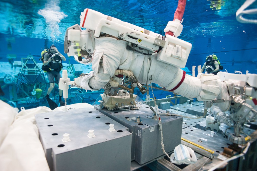
[Rationale: Safety is paramount for all EVA tasks. When translation paths and mobility aids are properly provided, they can reduce the hazards associated with colliding with hardware, intruding into keep-out zones, contacting sharp edges and burrs, or contacting contaminated surfaces. Without predefined translation paths and carefully located mobility aids, items or equipment not intended as mobility aids can be damaged from induced loads, such as grabbing, pushing, and pulling.]
8.4 Hatches and Doorways
See Appendix C for definitions of Hatch, Hatch Cover, Hatchway, Door and Doorway.
8.4.1 Operability
8.4.1.1 Hatches and Door Operation without Tools
[V2 8022] Hatches and doors shall be operable on either side by a single crewmember without the use of tools in expected gravity conditions, orientations, suit configurations, and operational configurations.
[Rationale: Hatch operation includes equalizing pressure, unlatching/opening, and latching/closing the hatch to enable translation through or isolation of pressurized volumes. Hatches must be designed for single crew operation since they may be in a small volume or in an escape route and need to be quickly opened by the first crew there. Tool use for manual pressure equalization and opening/closing hatches is prohibited to avoid hatch operation delays or failures. Lost or damaged tools may prevent hatches from being opened/closed resulting in loss of crew (LOC) or loss of mission (LOM). Gravity conditions, hatch orientations, and suit configurations are considered in hatch design and operations as they impact crew task posture, strength motion, deconditioning, and safety. When there are program/project needs for hatch and door tool provisions, an exception or waiver to this document may be necessary.]
8.4.1.2 Unlatching Hatches
[V2 8023] Hatches shall require two distinct and sequential operations to unlatch.
[Rationale: Inadvertent hatch opening, and subsequent cabin depressurization would be catastrophic. Requiring two separate, distinct operations helps to ensure that the hatch will not be unlatched through accidental contact.]
8.4.1.3 Hatch and Door Operating Times
[V2 8024] For nominal operations, hatches and doors shall be operable by a single crewmember in no more than 60 seconds, from both sides of the hatch.
[Rationale: Hatch operation includes unlatching/opening or latching/closing the hatch. Excessively long operating times can delay crews on both sides of a hatch, which would prevent ingress or egress. The hatch operating requirement of 60 seconds is based on engineering judgment related to easily operable hatch design without complicating hatch design and includes time for a deconditioned crewmember to operate hatch. This does not preclude a program/project from implementing more strict design requirements. For guidance regarding emergency escape time, see requirement [V2 8014] Emergency Escape Paths in this NASA Technical Standard.]
8.4.1.4 Hatch and Door Operating Force
[V2 8025] The forces required to operate each crew interface for the hatches and doors shall be within the crewmember strength defined by requirement [V2 4104] Crew Operational Loads for the worst-case pressure differential and anticipated encumbering equipment and clothing.
[Rationale: All crewmembers are to be able to operate hatches and doors. Designing operating forces to the strength of the weakest crewmember ensures the crew can perform activities related to safety and to LOM. Determination of anticipated worst-case parameters can be made through a detailed task analysis. For example, in 1997, a Progress collided with Mir and caused a cabin depressurization; the crew were unable to close the hatch due to the force of the rushing air.]
8.4.2 Hatchway and Doorway Design
8.4.2.1 Hatchway Size and Shape
[V2 8027] Hatchways and doorways shall be sized and shaped to accommodate all planned translations, including unrestricted passage of a suited crewmember and crewmembers carrying cargo or equipment.
[Rationale: A pressurized-suited crewmember represents a situation where the crewmember’s size is enlarged in many dimensions by virtue of the suit. Should a situation arise where the crewmember needs to move through hatchways and doorways while suited, especially in an emergency situation, the hatchways and doorways are to be large enough for the crewmember to pass safely and efficiently. Planned tasks include all nominal and planned contingency tasks. Also, reconfiguration of a spacecraft may require crewmembers to transport potentially large pieces of equipment across hatchways and doorways. Hatchway size must also consider the capability for a rescuing crewmember to be able to transport an incapacitated crewmember without being hampered by inadequate hatchway or doorway sizes. Hatchways and doorways may be designed to accommodate translation of robotic agents, but still accommodate crewmembers and their equipment.]
8.4.2.2 Pressure Equalization across the Hatch
[V2 8028] Each side of each hatch shall have manual pressure equalization capability with its opposite side, achievable from that side of the pressure hatch by a suited or unsuited crewmember.
[Rationale: Air pressure is to be equalized on either side of a hatch to safely open the hatch. In some vehicle failure scenarios, non-manual methods for pressure equalization may fail. Manual pressure equalization enables hatch opening regardless of vehicle status. This capability does not need to be physically located on the hatch if task analysis supports a different location.]
8.4.2.3 Visibility across the Hatch
[V2 8029] The system shall provide a window for direct, non-electronic visual observation of the environment on the opposite side of the hatch.
[Rationale: Direct visual observation of the environment on the opposite side of the hatch allows the crew to determine the conditions or obstructions for safety purposes, such as the presence of fire or debris. Windows do not have the failure modes associated with cameras and display systems that may not be operable during emergencies when most needed. While cameras or other sensors may be used to supplement the situational awareness afforded by a window, those systems alone do not meet the intent of this requirement. The minimum window field of view and what environmental conditions must be detected for crew and vehicle safety will be determined via task analysis, and verification is to be done through the observation of the volume on the opposite side of the hatch in both viewing directions (internal to external and viceversa for crew and vehicle safety) via a flight-like hatch window in flight-like configuration to determine if the objects or conditions identified via task analysis can be detected. Hazards may be assessed to determine if sensors, cameras, and procedural processes can be considered in lieu of windows for certain vehicles/modules not meant for habitation.]
8.4.3 Hatch and Door Design
8.4.3.1 Hatch, Hatch Cover and Door Interference
[V2 8030] When opened, hatches, hatch covers and doors shall allow for unrestricted flow of traffic.
[Rationale: Open hatches, with or without hatch covers, and doors are not to protrude into translation space and inhibit the safe and effective movement of both the crewmembers and any equipment they need to move from one location to another. In addition, open hatches, with or without hatch covers, and doors are to allow for a clear emergency translation pathway.]
8.4.3.2 Hatch Closure and Latching Status Indication
[V2 8031] Pressure hatches shall indicate closure and latching status on both sides of the hatch.
[Rationale: Indication of hatch closure and latch status on both sides of the hatch allows both ground personnel (launch pad) and crewmembers to verify that each hatch is closed and latched. For cases in which multiple latches must close in order to secure a hatch, this requirement applies to the system-level latched status of the hatch. By providing both closure and latch position status, proper security of the hatch can be verified. Hatch closure implies that the hatch is in proper position to be latched.]
8.4.3.3 Hatch Pressure Indication
[V2 8032] Pressure hatches shall indicate, viewable from both sides of the hatch, pressure differential across the hatch.
[Rationale: Indication of pressure difference on both sides of the hatch allows both ground personnel and crewmembers to see the changes in pressure across the hatch and to know when the pressure difference is low enough to safely open the hatch. Use of numerical values, color, or other cues can be used to indicate when it is safe to operate a hatch. Direct, non-electronic pressure difference measurement and display on both sides of the hatch will allow both ground personnel and flight crew to see a direct measurement and view the changes in pressure across the hatch to know when the pressure difference is low enough to safely open the hatch, without reliance on mental calculations or being subject to failure modes of an electronic display. This function is especially needed during an emergency. Direct measurement display does not need to be directly on the hatches but must be viewable by the crew at the hatch worksite while operating the hatch.]
8.4.4 No Drag-Throughs
[V2 8101] Hatchways shall be clear of drag-throughs.
[Rationale: During emergencies, hatchways may need to be closed quickly; and their function must be un-inhibited by items. Hatchways must remain clear of items, including, but not limited to, cargo, cables, and wires. For example, during a cabin depressurization, the crew will need to immediately close a hatch, which cannot be inhibited, like what occurred on Mir when there was a resupply vehicle collision with the U.S. habitat module, and the crew could not quickly close the hatch because of the obstructions in the hatchway.]
8.5 Restraints and Mobility Aids
In reduced gravity and dynamic acceleration environments, restraints are needed by crew to position and stabilize themselves and protect from injury. Restraints are also needed to react to operational forces, such as during hatch opening/closing operations. The design and placement of crew restraints begins with crew task and worksite analysis to determine physical task factors such as crew body positions (e.g., workstation, sleep, personal hygiene, medical treatment), suit configuration (e.g., suited or unsuited, pressurization, gloves, boots), movement action (e.g., single- or two-handed operation), movement direction, range of motions, force, duration, etc.
8.5.1 Restraints for Crew Tasks
[V2 8033] The system shall provide restraints for expected crew operations.
[Rationale: In reduced gravity and dynamic acceleration environments, restraints are needed by crewmembers to position and stabilize themselves and protect from injury across a wide range of operations as identified by task analysis. Restraints are also needed to react to operational forces, such as during hatch opening/closing operations. In the absence of intentional restraints, ISS experiences have shown that crew will use convenient physical features to stabilize themselves. Hardware failures have occurred due to unplanned use of features that were not designed to withstand loads or repeated use. The design and placement of crew restraints begins with crew task and worksite analysis to determine physical task factors such as gravity conditions (e.g., micro, partial, or 1-g), crew body positions (e.g., workstation, sleep, personal hygiene, medical treatment), operational configuration (e.g., suited or unsuited, pressurization, gloves, boots, PPE), movement action (e.g., single- or two-handed operation), movement range and direction, force, duration, etc. Worksite analysis is an extension of the task analysis to further describe the expected physical interactions between the crew and their system interfaces.
Factors that contribute to satisfying this requirement are as follows:
- Restraints do not impede task performance.
- Potential gravity conditions (e.g., micro, partial, or 1-g) are accommodated for.
- Potential crew body positions (e.g., workstation, sleep, personal hygiene, medical treatment) are accommodated for.
- Potential body postures and joint angles are accommodated for. Suited posture, joint angles, and range of motion are unique and are factored into the design of suit restraints for EVAs, airlock, etc.
- Potential operational configurations (e.g., suited or unsuited, pressurization, gloves, boots, PPE) are accommodated for.
- Intended movement actions (e.g., single- or two-handed) are decided and accommodated for.
- Potential movement range and direction are accommodated for.
- Potential effects from use duration (e.g., pain or fatigue from an extended duration) are accommodated for.
- The amount of force a crewmember could potentially impose on a restraint (and vice-versa) is accommodated for.
- Standardizing the form factor of restraints to help the crew easily identify and use intentional restraints.
Factors that could improve ease of use, cost, and complexity are as follows:
- Designing restraints for multi-purpose use such as designing cargo straps to also be used as foot restraints during cargo operations.
- Making restraints adjustable to account for variations in crew anthropometry or range of motion.]
8.5.2 Restraint and Mobility Aid Standardization
[V2 8038] Restraints and mobility aids shall be standardized, clearly distinguishable, and located to aid crewmembers in starting or stopping movement, changing direction or speed, or translating equipment.
[Rationale: Restraints and mobility aids such as handholds and foot restraints allow crewmembers to efficiently move from one location to another in microgravity, as well as reduce the likelihood of inadvertent collision into hardware that may cause damage to the vehicle or injury to the crew. Without predefined restraints and mobility aids, personnel may use available equipment that may be damaged from induced loads. By standardization of the restraints and mobility aids, reduction in crew training can occur, and the aids can be easily identified when translating inside or outside the spacecraft. Commonality among visual cues is important so that crews can easily distinguish intended restraints and/or mobility aids from equipment or structures that may be damaged by the application of crew-induced loads. During emergencies, crews need to be able to quickly discern restraints and/or mobility aids from the surrounding structures. Visual cues such as color coding may aid in this function.]
8.5.3 Mobility Aid for Assisted Ingress and Egress
[V2 8040] Mobility aids shall be provided for the assisted ingress and egress of suited or unsuited crewmembers.
[Rationale: Crewmembers needing assistance (including suited crew, in either pressurized or unpressurized suits, or unsuited crew) may be unable to ingress or egress spacecraft and may also be in a constrained position that requires assistance from another person. Moving the crew may include ingress from EVA or ingress/egress to/from another spacecraft from EVA or any vehicle or module to which a spacecraft is docked. Mobility aids are employed to protect crewmembers from a fall when descent from height is necessary to reach surface for EVAs. Assisting crew may need mobility aids not only for translating but also for stabilization during the translation of the incapacitated crewmember. Note that the term “mobility aids” is not intended to indicate a specific design solution; rather, the intent is to ensure that physical design of vehicles accommodate operations such as those described here. Mobility aids may refer to specially designed hardware (e.g., handholds) or the use of existing features of the system for mobility (e.g., a handle on a hatch), in which case additional testing and verification may be required.]
8.5.4 Unassisted Ingress, Egress, and Escape Mobility Aids
[V2 8041] Mobility aids shall be provided for ingress, egress, and escape of crewmembers without assistance from other crew or ground personnel.
[Rationale: In off-nominal situations, the crew may need to ingress, egress, or escape unassisted while suited or unsuited. Because a suited crewmember has limited maneuverability, mobility aids allow a more safe and efficient ingress and egress of the vehicle and escape from the pad. Mobility aids are employed to protect crewmembers from a fall when descent from height is necessary to reach surface for EVAs. Note that the term “mobility aids” is not intended to indicate a specific design solution; rather, the intent is to ensure that physical design of vehicles accommodate operations such as those described here. Mobility aids may refer to specially designed hardware (e.g., handholds) or the use of existing features of the system for mobility (e.g., a handle on a hatch), in which case additional testing and verification may be required.]
8.5.5 Mobility Aid Provision
[V2 8042] Mobility aids shall be provided to support all expected suited and unsuited tasks.
[Rationale: Mobility aids must support all tasks, which may be suited or unsuited. Because of the limited maneuverability of a suited crewmember, mobility aids are required to allow crewmembers to safely and efficiently ingress and egress the vehicle in both microgravity and on the surface. Predefined mobility aids help prevent personnel from using available equipment that may be damaged from induced loads. Mobility aids are to be designed to accommodate a pressurized-suited crewmember by providing clearance, non-slip surfaces, and noncircular cross sections.
- Microgravity operations considerations: Early experience in the Skylab program showed the problems of movement in microgravity. Stopping, starting, and changing direction all require forces that are best generated by the hands or feet. Mobility aids such as handholds and foot restraints allow crewmembers to efficiently move from one location to another in microgravity, as well as reduce the likelihood of inadvertent collision into hardware that may cause damage to the vehicle or injury to the crew. Appropriately located mobility aids make this possible. Mobility aids for microgravity suited operations must be provided along the expected translation paths of suited crewmembers at an interval that accommodates the suited crewmember’s reach.
- Surface operations considerations: Experience in the Apollo program showed the problems of movement in partial gravity due to the lack of reaction forces which caused issues ambulating and utilizing tools that provided torque. Mobility aids will be required when ingressing and egressing a vehicle as well as to protect crewmembers from a fall when descent from height is necessary to reach surface for EVAs. Multi-purpose mobility aids could help reduce the number of items required (e.g., a surface EVA mobility aid may serve as a cart for ICR transport, provide additional lighting, and be a UHF/wifirepeater).]
8.6 Windows
Windows are an integral part of many aspects of spaceflight operations with respect to their location, optical properties, fields of view, and protection. The minimum critical design parameters for windows to support these operations and tasks are size, color balance, haze, transmittance, wavefront quality, reflectance, material inclusions, surface defects, ambient illumination, visual obstructions, e.g., mounting for optical hardware and cameras, internal and external contamination, the position of windows on the spacecraft, and the distance, position, and orientation of the user relative to a window.
8.6.1 Window Provisioning
[V2 8043] The system shall provide windows with unobstructed fields of view for expected crew operations.
[Rationale: Windows provide direct, non-electronic, through-the-hull viewing and are essential to mission safety and success, as well as to maintaining crew psychological and physical health and safety. They support crew photography (a primary on-and-off duty activity of onboard crews), provide situational awareness of the external environment, facilitate piloting and robotic operations, and permit safe viewing through hatches. Windows also permit stellar navigation, vehicle anomaly detection and inspection, and environmental and scientific observations. Windows do not have the failure modes associated with cameras and display systems that may not be operable during emergencies when most needed. The following hardware is not considered an obstruction to the window field of view: (1) hardware designed and intended to protect and cover windows; (2) hardware used in conjunction with piloting (i.e., Head’s Up Display (HUD), Crew Optical Alignment System (COAS), or other similar equipment); (3) the outer mold line and hull structure of the vehicle, other windows, and window mullions; and (4) instrumentation applied within 13 mm (0.5 in) of the perimeter of the viewing area.]
8.6.2 Window Optical Properties
[V2 8045] System windows shall have optical properties commensurate with crew task needs.
[Rationale: System windows are required to have the optical properties necessary to prevent degradation of visual acuity and optical performance. JSC-66320, Optical Property Requirements for Glasses, Ceramics, and Plastics in Spacecraft Window Systems, specifies optical properties for different types of system windows according to their associated tasks (the uses to which they will be put). These optical properties provide system windows with the minimal optical performance necessary to support those tasks and permit the retrieval of imagery through windows so that the retrieved images are not blurred, degraded, or distorted. This requirement applies to all types of windows provided by the system.]
8.6.3 Window Light Blocking
[V2 8049] Each system window shall provide a means to prevent external light from entering the crew compartment, such that the interior light level can be reduced to 2.0 lux at 0.5 m (20 in) from each window.
[Rationale: External illumination can interfere with internal spacecraft operations such as crew sleep and onboard still and motion imaging, particularly if the illumination causes glare. Shades and shutters block external illumination from entering the habitable volume through windows. This requirement applies to all types of windows provided by the system.]
8.6.4 Window Accessory Replacement/Operation without Tools
[V2 8050] System window accessories designed for routine use shall be operable by one crewmember and be removable or replaceable without the use of tools.
[Rationale: System window accessories such as window covers, shades, and filters are to be designed to be easily installed and removed using their attachment features without additional tools. The ability to remove, open, replace, or close window accessories efficiently ensures proper use of the hardware and appropriate protection for the windows and the crew. This requirement applies to all types of windows provided by the system.]
8.7 Lighting
Lighting affects a crew’s visual ability, health, and safety. This section defines requirements for adequate interior and exterior lighting, prevention of distractive lighting, compatibility of lighting with sleep cycles, and informative lighting. Exterior operations and environments such as EVAs and extraterrestrial surfaces pose unique challenges to lighting solutions. The overall lighting environment cannot be controlled to the extent that it can inside a vehicle. The presence (and angle) or absence of the Sun must also be taken into consideration.
Note: The interrelationship of task illumination, chromaticity, color fidelity, and circadian requirements are linked together and require developments of these requirements together.
8.7.1 Illumination Levels
[V2 8051] For interior architectures and exterior operations that do not include the presence of orbital sunlight, the system shall provide illumination levels to support the range of expected crew tasks, at minimum, per Table 8.7-1—Surface Illuminance Levels, that accommodate both human observers and remote camera systems.
[Rationale: A wide range of crew tasks is expected to be performed inside and outside the vehicle over the course of a mission. The required lighting levels vary, depending on the task being performed. For instance, cabin reconfiguration after orbit insertion may require simultaneous reading of labels and checklists, crew translation, mechanical assembly, and manual control at a variety of vehicle locations, each of which requires sufficient lighting without blockage from crew and equipment in transit. Similarly, rendezvous and proximity operations may require general cabin darkening for out-the-window viewing but sufficient lighting for crew translation and manual control. A single type of lighting at a single illumination level is insufficient to support all tasks; therefore, both general and task illumination are necessary. Illumination for exterior tasks, not related to translation, and associated with an exterior environment where sunlit surfaces are not within the field of view must consider a task analysis that factors in the surrounding architecture, tasks, and near, mid, and far field targets within the field of view, as competing targets may impact illumination requirement to ensure all required targets, within the field of view are within 2 orders of magnitude for surface luminance. Extraterrestrial lighting considerations, such as surface illumination and reflection, are to be addressed. These vary depending on the extraterrestrial body selected for the mission, as well as the location on that extraterrestrial body.]
Table 8.7-1—Surface Illuminance Levels
| Lighting Intensity Level | Lux | NOTE |
|---|---|---|
| Translation & Stowage | >= 108 | 5 |
| General Horizontal Ambient Lighting | >= 350 | 1, 5 |
| General Vertical Ambient Lighting | >= 200 | 2, 5 |
| Medical/Technical/Maintenance/Repair/PhotoTV Lighting | >= 750 | 3, 5 |
| Crew Sleep | >= 0.02 | 4, 5 |
Notes:
- Analysis of the architecture, micro-gravity tasks, and neutral body posture, shall determine a horizontal plan (elevation) for each unique habitat volume that best describes the location of the crew’s hands. The General Horizontal Ambient Lighting intensity shall be maintained within +/- 1ft (30cm) vertical height from the designated horizontal plane. Sensor orientation is pointed up (normal) towards the ceiling from the horizontal plane.
- Analysis of the architecture, micro-gravity tasks, neutral body posture, and critical panel locations, shall determine a center volume vertical plane and side-wall vertical plane that best describes the location of crew’s hands or controls within reach of an un-restrained crewmember. The General Vertical Ambient Lighting intensity shall be maintained within the area of the designated vertical plane. Sensor orientation is pointed normal from the vertical plane (towards observer).
- Analysis of location(s) where these tasks are to be performed (permanent/fixed location or temporary) shall determine surface size and orientation for the task. The Medical/Technical/Maintenance/Repair/PhotoTV Lighting intensity shall be maintained within the designated areas. Sensor orientation is pointed normal from the surface of the plane towards the observer.
- Analysis of crew sleep restraints, locations, and micro-gravity impacts shall determine a surface area describing the average eye-point location for crew-sleep. The Crew Sleep intensity shall be maintained within +/- 6 inches from the normal vector of the eye-point plane. Sensor orientation is pointed normal from the surface away from the eyes/crew member.
- Area measurements will have a deviation from an average because of uneven light distribution. For each applicable illumination requirement, the stated light level shall be the “average” for the points representing the area, with a uniformity (average/minimum) ratio, no greater than 3:1 between points. The number of points to be measured describes the perimeter of the measurement and the surface area of the measurement. The distance between consecutive points within a measurement area does not exceed 1ft (30cm).
8.7.2 Environmental Lighting Attenuation
[V2 8103] The integrated system architecture shall provide countermeasures to attenuate environmental lighting and complement existing active lighting architecture.
[Rationale: For external operational conditions or internal operations via a window where tasks are to be performed under unchanging direct illumination of the Sun for a duration that impacts mission safety or success, interior countermeasures, exterior support systems, system components, and/or architectures for crewed extravehicular activity (EVA) and extravehicular robotics (EVR) need to provide passive (nonpowered architectural solutions)- or active (powered illumination sources) countermeasures for the attenuation of or diffuse scatter of collimated light, that creates performance issues due to high contrast within the critical area of observation. For external operations performed without direct sunlight, without indirect sunlight reflected from Earth, or without indirect sunlight reflected from the Moon, passive countermeasures from fixed architectural and portable surfaces are considered part of the integrated lighting solution when the primary light source is a lamp or system of lamps. Lighting analysis and optimization tasks consider how surface reflectance properties interact with the system architecture used to enhance the performance of the artificial lighting system. Environmental lighting can include sunlight, glare, reflection from lunar/planetary/vehicle surfaces, etc. Countermeasures can range from crewmember-worn PPE such as sunglasses or visors, to fixtures such as diffuser screens or reflecting panels. Exterior vehicle materials and colors can be chosen based on their reflective properties. They may be portable or considered as part of the integrated permanent worksite architecture.]
8.7.3 Task-Specific Exterior Lighting for Operational Areas Partially or Fully Lit by Sunlight
[V2 8104] For operational areas that include shadowed areas and areas illuminated by the Sun and celestial bodies, the system shall provide passive and/or active solutions that reduce the contrast within shadowed areas of worksites/tasks to within 2 orders of magnitude of the predicted maximum surface luminance of objects, that accommodate both human observers and remote camera systems.
[Rationale: During operations performed under unchanging direct illumination of the Sun, exterior support systems, system components, and architectures for crewed extravehicular activity (EVA) and extravehicular robotics (EVR) must provide active lighting support solutions that decrease the contrast within worksites. Collimated sunlight creates a high contrast operational environment due to the creation of shadows from the “fixed” surrounding architectures and mobile “operators”. This contrast between illuminated areas and shadowed areas can impact performance and safety. Contrast can be reduced by increasing the luminance (candela/m2) using active powered illumination sources, or by decreasing the maximum surface luminance of objects using non-powered passive architectural solutions. The luminance range of the visual field(s) of the operation dictates the support requirements for supplemental systems to bring the luminance range within a usable condition for the human observer and for remote monitoring technologies. For external operational conditions where operations are to be performed without direct sunlight, without indirect sunlight reflected from Earth from low earth orbit, or without indirect sunlight reflected from the Moon from lunar orbit, the integrated lighting solution provides surface illuminance with the same required target range as interior lighting systems.]
8.7.4 Navigation and Wayfinding (Exterior)
[V2 8105] The system shall provide luminous powered and passive indicators that assist with proximity, navigation, and object recognition for validation of targets critical to the surface operation.
[Rationale: On an unfamiliar extraterrestrial surface, navigation can be difficult. On the Lunar surface, for example, the horizon is less than 2.5 km from a human observer, limiting line-ofsight. Depending on the position of the Sun, long shadows can present further challenges. These wayfinding markers must have features that distinguish them from the background environment. Capabilities may include bright lights, strobing, and/or alternating colors that can help crewmembers easily locate the markers to orient themselves. This function may also be provided by other means such as global positioning systems (GPS) and/or communication structures (i.e., towers, vehicles) and tracking.]
8.7.5 Emergency Lighting
[V2 8053] The system shall provide emergency lighting (interior and exterior) to maintain visibility in the event of a general power failure.
[Rationale: Emergency lighting is a part of the overall lighting system for all vehicles and surface operations. It allows for crew egress/translation and/or operational recovery in the event of a general power failure. The emergency lighting system is to be automatically activated to allow operators and other occupants of a vehicle to move to a safe location and allow efficient transit between any inhabited location and designated safe haven(s). Efficient transit includes appropriate orientation with respect to doorways and hatches, as well as obstacle avoidance along the egress path.]
8.7.6 White Lighting Chromaticity
[V2 8059] Interior and exterior lighting intended for operational environments requiring human/camera color vision shall have a chromaticity that falls within the chromaticity gamut for white light for the Correlated Color Temperature (CCT) range of 2700 K to 6500 K as defined by ANSI C78-377, Electric Lamps—Specifications for the Chromaticity of Solid-State Lighting Products.
[Rationale: The ability to make variable customized lighting spectra adds risk that an implementer will come up with a light that meets some color constraints but fails to create an environment that appears white or will create one in which cameras have trouble operating. ANSI C78-377 (see NEMA C78.377) forces the definition of white to be a color gamut along the blackbody locus of the International Commission on Illumination (CIE) 1931 chromaticity chart. For variable CCT systems, it is important that humans and cameras within that environment see color correctly and interpret the light as white light anywhere along the color range of white light as defined by ANSI C78-377. Exceptions to this requirement include conditions that do not require color vision such as window operations and sleep environment, as determined by a task analysis. This technical requirement is only for white light and does not apply to the definition of chromaticity of lamps intended for indication purposes (white strobes, white indicators, green, red, etc., lights).]
8.7.7 White Lighting Color Accuracy
[V2 8060] Interior and exterior lighting intended for human operational environments requiring photopic vision accuracy shall have a score of 90 ±10 on a color fidelity metric that is appropriate for the utilized lighting technology, as designated by the Color Fidelity Metric (Rf) defined by IES TM-30, Method for Evaluating Light Sources Color Rendition methodology.
[Rationale: Accurate representation of the colored environment impacts several areas of concern for human performance and behavior, including critical color matching tasks (e.g., matching litmus strips to cue cards) and the representation of skin tone and biological material (e.g., for health diagnostics). Rapid advancements in modern lighting technology such as solidstate lighting require careful consideration of the proper color fidelity metric selection for the evaluation of color rendition properties of a light source. Color Rendering Index (CIE CRI Ra) is the first established color fidelity metric; it is widely used but it is an improper metric for sources below CCT of 5000 K as well as sources with peaked spectra such as solid-state technology. Color Quality Scale (CQS) improves upon the methodology of CRI to more accurately describe color hue and saturation shifts. For a complete suite of color rendition metrics, the IES TM-30 method is recommended. TM-30 provides a color fidelity metric (Rf) that is analogous to CRI Ra but more accurate, a color gamut index (Rg) to describe color saturation, and a color vector graphic for visualization of hue and saturation changes with respect to a reference source. IES TM-30 has an extensive toolset for evaluation of the ability of a lamp to properly render colored materials within an environment. This toolset is advanced from the Color Quality Scale and provides a means to evaluate the performance of a lighting system with any material, given its spectral reflectance, allowing for tailoring for programspecific critical colored surfaces. It is highly recommended that this tool be included in any lighting performance specification. Situations to which this requirement applies are determined by a task analysis. This technical requirement is only for white light and does not apply to the definition of chromaticity of lamps intended for indication purposes (white strobes, white indicators, green, red, etc., lights).]
8.7.8 Physiological Effects of Light (Circadian Entrainment)
[V2 8055] The system shall provide the levels of light to support the physiological effects of light in accordance with Table 8.7-2—Physiological Lighting Specifications.
[Rationale: Light is both a stimulant and the most effective signal for entraining and resetting the circadian clock. The magnitude of these effects depends primarily on the intensity, spectrum, timing and duration of light. Lighting Systems must provide proper light to promote alertness during wake and work hours, promote sleepiness during the ‘pre-sleep’ time, and promote or avoid circadian resetting when required. Failure to provide adequate lighting during wake will lead to suboptimal alertness and performance. Failure to provide appropriate lighting during pre-sleep will lead to prolonged sleep latency, reduced sleep duration and reduced sleep quality, and suppression of the pineal ‘darkness’ hormone melatonin. Failure to provide an adequate 24hour light-dark cycle (or a 24-hour and 40-minute cycle for Mars missions) will lead to misalignment between the circadian clock and the rhythms the clock controls including, but not limited to, sleep, performance, mood, metabolism, endocrine function, immune function, reproductive function and glucose and lipid regulation. It is important to note that in the absence of an appropriate light signal, the circadian rhythm will IMMEDIATELY begin to mis-align, which is why it is necessary to require lighting sufficient for entrainment on short-duration missions. Failure to provide appropriate circadian resetting in response to a shift schedule will also lead to circadian misalignment.]
Table 8.7-2—Physiological Lighting Specifications
| Lighting Levels at Cornea |
Melanopic EDI Lux | Melanopic DER | Peak Wavelength | NOTE |
|---|---|---|---|---|
| General Ambient Lighting |
≥ 250 | ≥ 0.7 | 480 ± 10nm (blueenriched) | 1, 2 |
| Crew Pre-Sleep | 8 +/- 2 | ≤ 0.3 | ≥ 550nm (blue-depleted) | 1, 3 |
Notes:
- Melanopic EDI is measured at the cornea in the vertical plane. Both EDI and DER thresholds for each lighting condition must be met.
- During all waking hours, the white light must be ‘blue-enriched’ to maintain alertness and entrainment of the circadian pacemaker to a 24-hour day and facilitate schedule shifting when required.
- During scheduled pre-sleep, the white light must be ‘blue-depleted’ to reduce alertness and prepare the brain for sleep.
- Melanopic Equivalent Daylight Illuminance (EDI, in melanopic lux) and melanopic Daylight Equivalent Ratio (DER, no units) shall be calculated according to the most recent version of the International Commission on Illumination (CIE) International Standard: CIE S 026:2018. System for Metrology of Optical Radiation for ipRGCInfluenced Responses to Light. CIE, Vienna (DOI: 10.25039/S026.2018)
- CIE Position Statement on Non-Visual Effects of Light. 2019 https://cie.co.at/files/CIE%20Position%20Statement%20-
%20Proper%20Light%20at%20the%20Proper%20Time%20(2019)_0.pdf - Brown, T.; Brainard, G.; Cajochen, C.; Czeisler, C.; Hanifin, J.; Lockley, S.; Lucas, R.; Munch, M.; O’Hagan, J.; Peirson, S.; Price, L.; Roenneberg, T.; Schlangen, L.; Skene, D.; Spitschan, M.; Vetter, C.; Zee, P.; Wright Jr., K. Recommendations for Healthy Daytime, Evening, and Night-Time Indoor Light Exposure. Preprints 2020, 2020120037 (doi: 10.20944/preprints202012.0037.v1).
8.7.9 Lighting Controls
[V2 8056] Lighting systems shall have on-off controls.
[Rationale: Controls for turning lighting on and off within each module allow crewmembers to see the effect of changes to lighting controls without changing their location. Easy access to the controls is necessary. Light sources are to be capable of being turned completely off and returned to on. This control allows for conservation of lamps that would otherwise be noncontributory due to blockage by configuration of equipment, crew gear, payloads, stowage containers, deployed sun shields, etc.]
8.7.10 Lighting Adjustability
[V2 8057] Interior and exterior lights shall be adjustable (dimmable).
[Rationale: Interior and exterior lighting is to be adjustable as needed by the crew to accommodate task-specific lighting needs.]
8.7.11 Glare Prevention
[V2 8058] The integrated system architecture including surrounding surfaces, support equipment, visualization tools, and supporting lighting systems shall work in conjunction to minimize visibility and eye-safety impacts from direct and indirect glare.
[Rationale: Glare must first be eliminated though proper consideration and arrangement of the spacecraft internal system architectural environment, including the lighting system, window design, architectural surface treatments, and backlit displays. In situations where this perfect arrangement is not possible, mitigating measures such as lighting source baffles, window shades, and computer monitor glare shields can be used. Eye discomfort can occur, and visual performance can be negatively affected by glare. If a light source within the observer’s field of view provides much more luminance than its surroundings (higher range of contrast) and occupies a significant portion of the field of view, it may act as a direct glare source. If the reflection of a light source from a surface within the field of view provides an area whose luminance greatly exceeds that of its surroundings, it may act as a reflected (indirect) glare source. The types of tasks expected to be performed are to be considered, as well as the location where the tasks occur, whether they are internal or external to the vehicle, and whether they are on or off a planetary surface. For applications where a human is a primary observer and dominant surface features, for the field of view of the operation, are less than 50% reflective, or if the primary surfaces have highly specular surface properties, the integrated lighting solution are to include countermeasures for direct glare (to reduce luminance) from reflected light from specular objects, while adjusting surface contrast ratio (max luminance of adjusted visual field/luminance of critical task surface) of the visual field to meet contrast performance objectives, while maintaining acceptable thresholds for color vision and visual acuity. Eye safety impacts and limits are further discussed in [V2 6117] Artificial Lighting Exposure.]
8.7.12 Extraterrestrial Surface Transport Vehicle (ESTV) Dashboard and Control Lighting
[V2 8106] The system shall provide active lighting and attenuation of solar light for manual controls (e.g., unpressurized surface transport vehicle joystick controls, switches and dashboard) and display screens to be visible in all potential natural light levels, including complete darkness.
[Rationale: ESTV activities will likely go between areas of intense natural light and a complete absence of natural light, often near-instantaneously. Proper lighting of manual controls (joysticks, switches etc.) and display screens must be visible under all conditions to ensure safe and effective control of the ESTV. Care must also be taken that dashboard lighting does not cause annoyances, such as reflections on ESTV windows. Factors that are to be considered in meeting this requirement include:
- Attenuation of ambient light that could obscure legibility of the instrument panel.
- Attenuation (or blocking) of glare sources within the field of view in the direction of travel.
- Controls to increase or decrease the luminance (cd/m^2) of backlit displays and indicators so that the crew can adjust contrast to be within adaptation levels.
- Surface materials that minimize reflections onto windows and displays that could obscure the field of view.
For requirements and guidance on display legibility see [V2 5051] Legibility and [V2 10048] Visual Display Parameters.]

