Journal Home Page | Apollo 17 Journal |
Animation made from seven LROC images of the Apollo 17 landing site, ordered from sunrise to sunset, and showing the changing length and location of the shadow cast by the U.S. flag erected by the crew. The frames are: (1) M116113215RC, Sun 8 degrees above the eastern horizon; (2) M131447374LC , 11 deg. east; (3) M129086118LC , 35 deg. east; (4) M109032389LC , 68 deg. east; (5) M134985003RC , 26 deg. west; and (6) M117291316LC , 5 deg. west. LROC images courtesy NASA/GSFC/Arizona State University. |
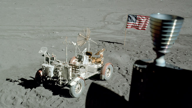
Detail from AS17-140-21354,
taken out the LMP window after EVA-2. The flag is
pointing in an easterly direction. At the end of
EVA-3, the Rover
was parked 128
meters from the LM on an azimuth of 112 (22 degrees
south of east). (Click on the image for a larger
version.) |
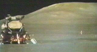
Image taken by the
Rover-mounted TV before Ascent Stage liftoff.
The camera was operated remotely from Houston. The
flag is still pointing in an easterly direction. |
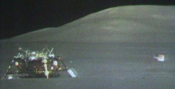
TV image taken after Ascent
Stage liftoff. The flag swung around to a
northerly direction because of engine exhaust.
Note that the fabric loop holding the bottom left
corner of the flag to the pole seems to have slipped
upward, raising that corner of the flag, at least
temporarily. Because the flag is outstretched
horizontally, parallel to the ground, perpendicular to
the Sun’s rays at dusk and dawn and not drooped or
tilted, it will cast the best possible shadows
for imaging by the LROC. |
This stack displays the six
LROC images details used to make the animation at the top
of the page. The vertical yellow lines approximate
the east-west location of the flagpole. In the early
morning images at the top of the stack, the flag shadows
start from points west of the flagpole and end farther
west. The situation is reversed for the late
afternoon images at the bottom of the stack. |
Preflight image of an Apollo
flag assembly, possibly Apollo 11. The upper part of
the flagpole is at the top, with the support rod for the
top of the flag attached by a latching hinge at the
right. The bottom section of the pole is below those
two items. The portion of the bottom section that is
pushed or hammered into the surface on on the right, with
two short knurled sections indicating how far the pole
should be pushed in for adequate stability. |
Journal Home Page | Apollo 17 Journal |