 |
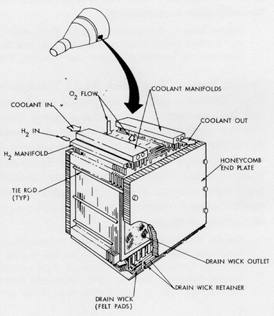
| Figure 46. Gemini fuel cell stack. (McDonnell, "Project Gemini Familiarization Manual: Manned Spacecraft Rendezvous Configuration," June 1, 1962, p. 4-6.) |
| Figure 45. The five consoles to be installed in each tracking network remote station. (NASA Photos S-63-22136 and S-63-22135, undated.) |
 |
| Figure 46. Gemini fuel cell stack. (McDonnell, "Project Gemini Familiarization Manual: Manned Spacecraft Rendezvous Configuration," June 1, 1962, p. 4-6.) |
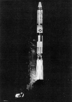 |
| Figure 47. Titan II flight N-15 was launched from Cape Canaveral on January 10, 1963. It was the tenth in the series of Titan II research and development flights, and the second to achieve significantly reduced levels of longitudinal oscillations by means of propellant tank pressurization. (USAF Photo 33-1, Jan. 10, 1963.) |
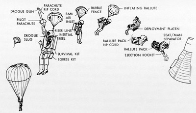 |
| Figure 48. Proposed deployment sequence for the ballute stabilization device. (NASA Photo No. 63-Gemini-12, Jan. 18, 1963.) |
| Figure 49A. Procedure for assembling fuel and oxidizer tanks for stage I of the Gemini launch vehicle. (Martin Photo 8B65793, undated.) |
| Figure 49B. Procedure for assembling fuel and oxidizer tanks for stage II of the Gemini launch vehicle. (Martin Photo 8B65794, undated.) |
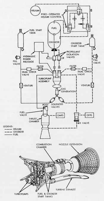 |
| Figure 50. Schematic and drawing of the primary propulsion system of the Gemini Agena target vehicle. (Lockheed, Gemini Agena Target Press Handbook, LMSC-A766871, Feb. 15, 1966, pp. 4-19, 4-20.) |
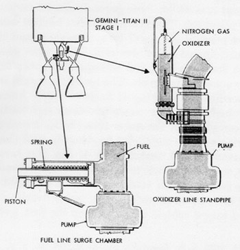 |
| Figure 51. POGO suppression equipment proved out in the Titan II development program. (Martin Photo 8B65766, undated.) |
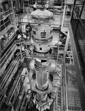 |
| Figure 52. Gemini launch vehicle 1 undergoing tests in the vertical test facility at Martin's Baltimore plant. (Martin Photo B-58332, undated.) |
| Figure 53. (A) Malfunction detection system (MDS) block diagram; (B) MDS display on Gemini spacecraft instrument panel. (Martin Photos 8B-67547 and 8B-65781, undated.) |
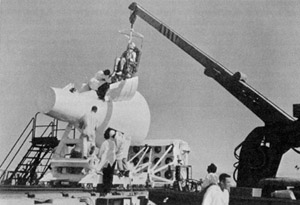 |
| Figure 54. Instrumented mannequin being lowered into a boilerplate Gemini spacecraft in preparation for a dynamic sled test of the Gemini ejection system. Notice the rocket motors at the rear of the sled that propelled it along the track. (NASA Photo 63-Gemini-60, released Sept. 30, 1963.) |
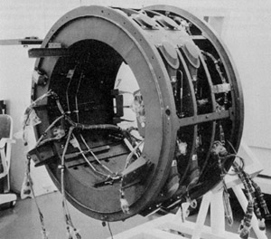 |
| Figure 55. The reentry control system unit for Gemini spacecraft No. 1 at the McDonnell plant. (NASA Photo #124, June 1963.) |
 |
|
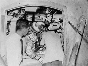
Figure 56. Dr. Howard A. Minners observes Astronaut Donald K. Slayton being readied for a run in the centrifuge at Aviation Medical Acceleration Laboratory, Johnsville, Pennsylvania. (NASA Photo S-63-11195, July 1963.) |
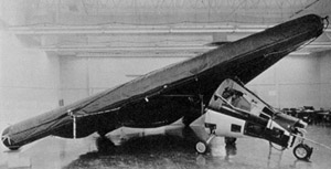 |
| Figure 57. The paraglider full-scale test vehicle in the Design Engineering Inspection briefing room at North American. (NASA Photo S-63-20931, undated.) |
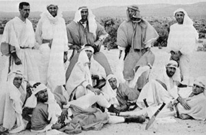 |
| Figure 58. Astronauts after a training session in desert near Stead Air Force Base, Nevada. Front row, left to right: Frank Borman, James A. Lovell, Jr., John W. Young, Charles Conrad, Jr., James A. McDivitt, Edward H. White II. Back row, left to right: Raymond G. Zedekar (Astronaut Training Officer), Thomas P. Stafford, Donald K. Slayton, Neil A. Armstrong, and Elliot M. See, Jr. (NASA Photo No. 63-Astronauts-135, released Aug. 16, 1963.) |
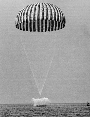 |
| Figure 59. Water impact test of the Gemini parachute recovery system in the Salton Sea, California. (Northrop Ventura Photo 0748-65-33328, undated.) |
 |
|
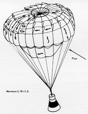
Figure 60. Sketch of the parasail landing system proposed for the Gemini spacecraft. (NASA Photo S-64-481, undated.) |
 |
| Figure 61. The sequence of events in the operation of the Gemini parachute recovery system incorporating the drogue chute. (Northrop Ventura Photo 0748-94-38242, undated.) |
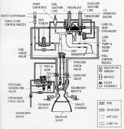 |
| Figure 62. Diagram of the Gemini launch vehicle stage II engine. (Martin Photo 8B-66461, undated.) |
| Figure 63. Instrumentation pallet for Gemini spacecraft No. 1: (A) left pallet, (B) right pallet. (NASA Photos S-64-3069 and S-64-3066, undated.) |
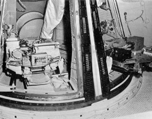 |
| Figure 64. Installation of right ballast seat and instrumentation pallet in Gemini spacecraft No. 1. (NASA-USAF Photo 63-13025, Dec. 7, 1963.) |
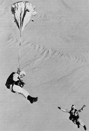 |
| Figure 65. Jump test of the 36-inch ballute with dual suspension at the Naval Parachute Facility, El Centro, California. The second figure is a free-falling photographer with a camera mounted in his helmet. A second observer jumped later and took this picture. (NASA Photo 64-Gemini-120, released Dec. 18, 1963.) |


