 |
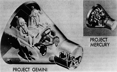
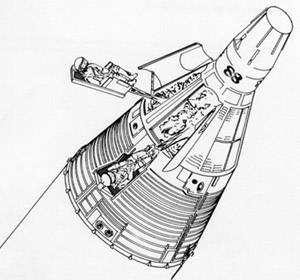
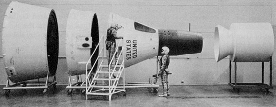
| Figure 11. The first illustration of the Gemini spacecraft to be released publicly. It was distributed at the same time NASA announced that the project was to be named "Gemini." (NASA Photo S-62-88, released Jan. 3, 1962.) |
|
| Figure 11. The first illustration of the Gemini spacecraft to be released publicly. It was distributed at the same time NASA announced that the project was to be named "Gemini." (NASA Photo S-62-88, released Jan. 3, 1962.) |
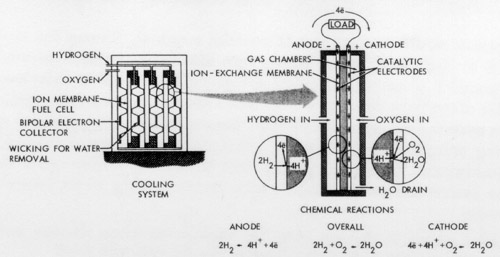 |
| Figure 12. The operating principle of the fuel cell designed by General Electric, adopted for use in the Gemini spacecraft. (McDonnell, "Project Gemini Familiarization Charts," June 5, 1962, unpaged.) |
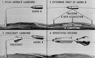 |
| Figure 13. Four stages in a rendezvous mission as conceived early in 1962. (NASA Photo S-62-82, c. Jan. 3, 1962.) |
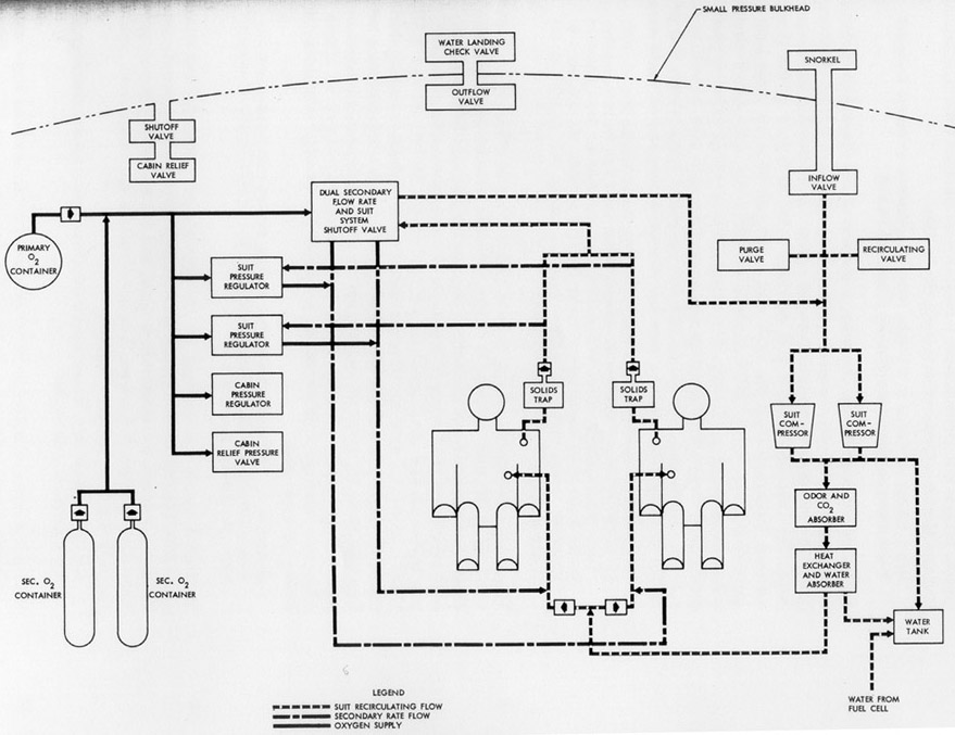
| Figure 14. Block diagram of the Gemini environmental control system, subcontracted by McDonnell to AiResearch Manufacturing Co. (McDonnell, "Project Gemini Familiarization Charts," June 5, 1962, unpaged.) |
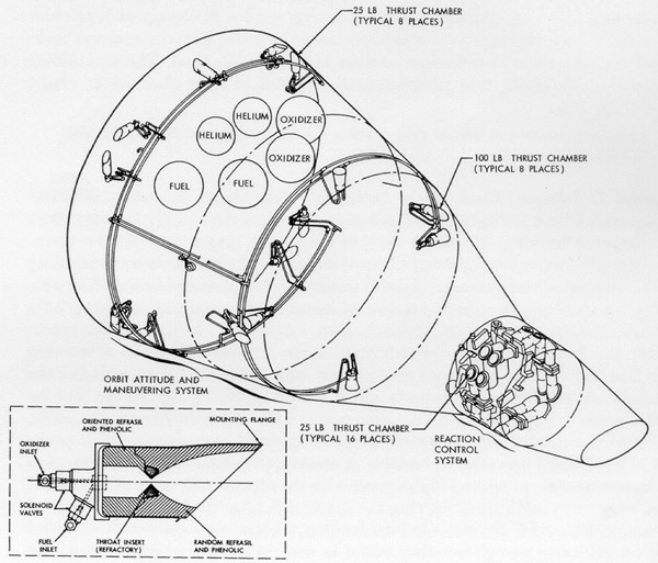 |
| Figure 15. The general arrangement of liquid rocket systems (OAMS and RCS) in the Gemini spacecraft. The insert displays a typical thrust chamber assembly. (McDonnell, "Project Gemini Familiarization Charts," June 5, 1962, unpaged.) |
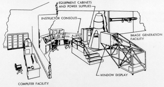 |
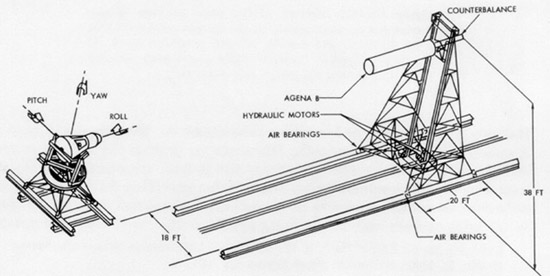
| Figure 16. The two major types of simulators to be used in training crews for Gemini missions. The Gemini flight trainer (above) would simulate the entire mission, while the docking trainer (below) would simulate the final stages of rendezvous. (McDonnell, "Project Gemini Familiarization Charts," June 5, 1962, unpaged.) |
 |
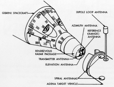 |
| Figure 17. The location of the main elements of the rendezvous radar system on the Gemini spacecraft and the Agena target vehicle. (Charts presented by R. R. Carley (Gemini Project Office), "Project Gemini Familiarization Briefing," July 9-10, 1962.) |
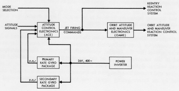 |
| Figure 18. A functional block diagram of the attitude control and maneuvering electronics system of the Gemini spacecraft. (McDonnell, "Project Gemini Familiarization Charts," June 5, 1962, unpaged.) |
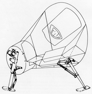 |
| Figure 19. Gemini landing gear: part of the land landing system along with the paraglider. (McDonnell, "Project Gemini Familiarization Charts," June 5, 1962, unpaged.) |
 |
| Figure 20. An artist's version of the use of ejection seats to escape from the Gemini spacecraft. The seats were to be used before launch (off-the-pad abort) or during the first phase of powered flight (to about 60,000 feet) if the launch vehicle malfunctioned. (McDonnell, "Project Gemini Familiarization Charts," June 5, 1962, unpaged.) |
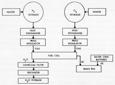 |
| Figure 21. Block diagram of the reactant supply system for the Gemini spacecraft fuel cells. (MSC Flight Crew Operations Division, Crew Engineering, "Gemini Familiarization Package," Aug. 3, 1962.) |
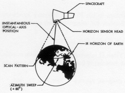 |
| Figure 22. Illustrating the operation of the horizon sensor for the Gemini spacecraft. (McDonnell, "Project Gemini Familiarization Charts," June 5, 1962, unpaged.) |
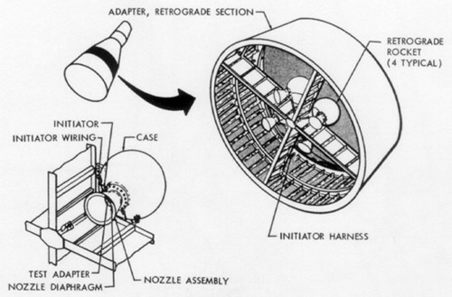 |
| Figure 23. Location and arrangement of the retrograde rocket system in the Gemini spacecraft. (McDonnell, "Project Gemini Familiarization Charts," June 5, 1962, unpaged.) |
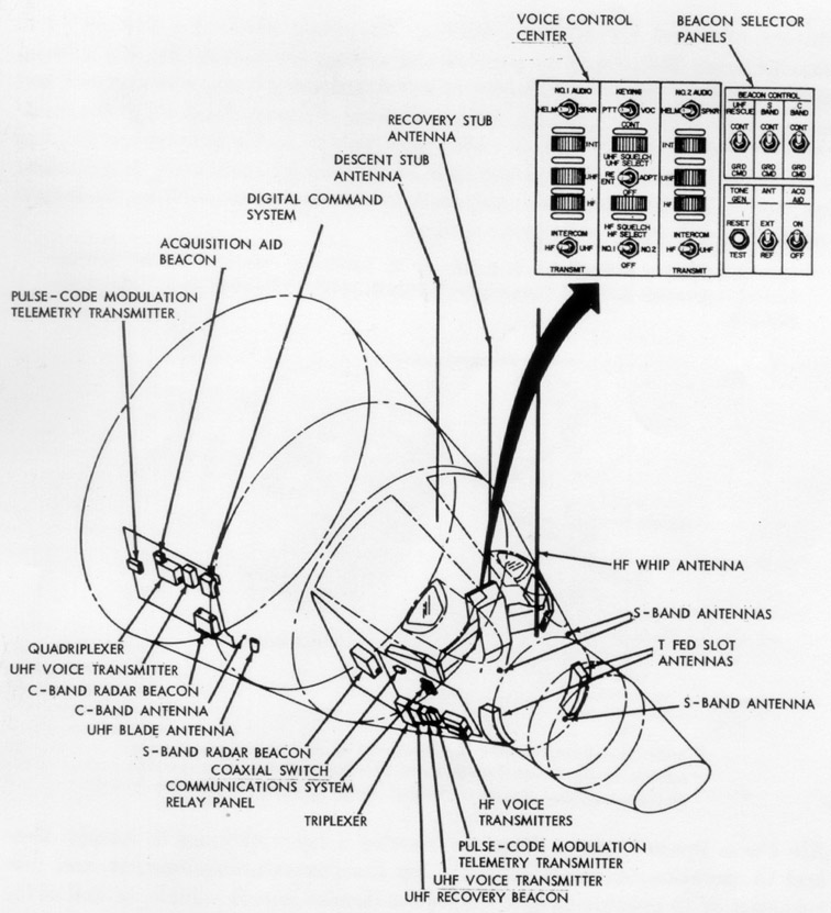
| Figure 24. Gemini spacecraft communications system, which received ground commands for transfer to spacecraft systems. (McDonnell, "Project Gemini Familiarization Manual: Manned Spacecraft, Rendezvous Configuration," SEDR 300, June 1, 1962, p. 8-1.) |
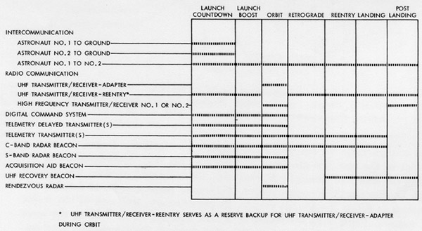 |
| Figure 25. Illustrating the stages of a mission during which various elements of the Gemini spacecraft communications system would be used. (Charts presented by J. Hoffman (GPO), "Project Gemini Familiarization Briefing," July 9-10, 1962.) |
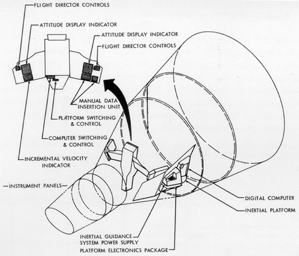 |
| Figure 26. The Gemini spacecraft inertial guidance system. (McDonnell, "Project Gemini Familiarization Manual: Manned Spacecraft Rendezvous Configuration," SEDR 300, June 1, 1962, p. 7-23.) |
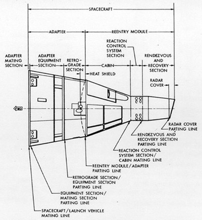 |
| Figure 27. Gemini spacecraft nomenclature. (McDonnell, "Project Gemini Familiarization Manual: Manned Spacecraft Rendezvous Configuration," SEDR 300, June 1, 1962, p. 2-3.) |
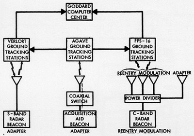 |
| Figure 28. Gemini spacecraft tracking aids (beacon system). (McDonnell, "Project Gemini Familiarization Charts," June 5, 1962, unpaged.) |
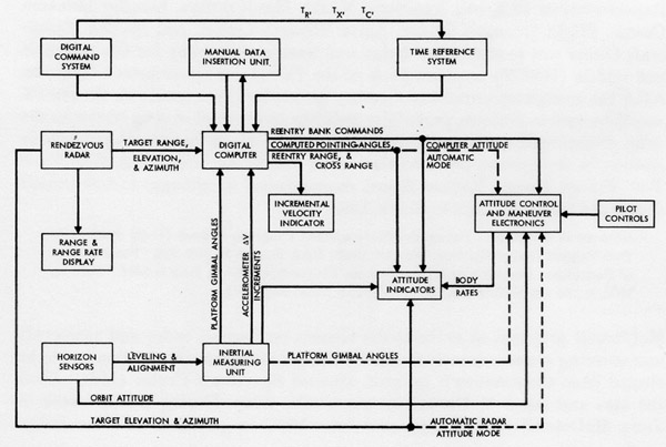 |
| Figure 29. Block diagram of the Gemini spacecraft guidance and control system. (McDonnell, "Project Gemini Familiarization Charts," June 5, 1962, unpaged.) |
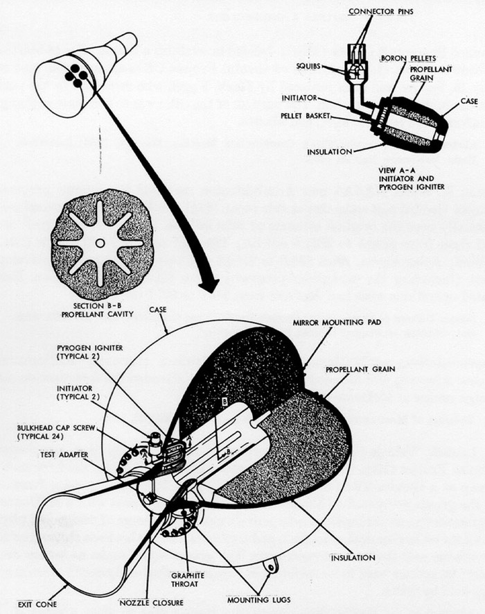
| Figure 30. The solid-propellant retrograde rocket motor for the Gemini spacecraft. (McDonnell, "Project Gemini Familiarization Manual: Manned Spacecraft Rendezvous Configuration," SEDR 300, June 1, 1962, p. 11-30.) |
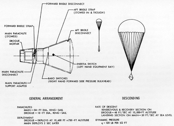 |
| Figure 31. The parachute recovery system to be used instead of paraglider on the first Gemini spacecraft: stowed and deployed modes. (McDonnell, "Project Gemini Engineering Mockup Review," Aug. 15-16, 1962, p. 39.) |
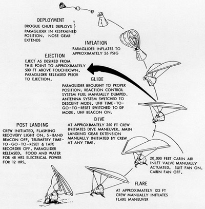 |
| Figure 32. The proposed sequence of events in deploying the paraglider to land the Gemini spacecraft. (McDonnell, "Project Gemini Familiarization Manual: Manned Spacecraft Rendezvous Configuration," SEDR 300, June 1, 1962, p. 12-8.) |
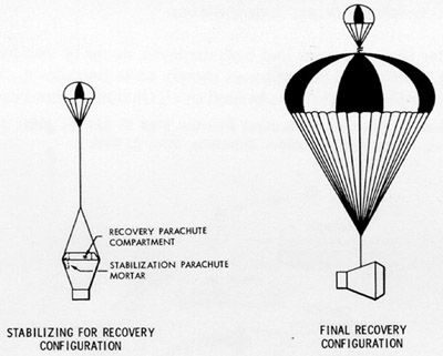 |
| Figure 33. The emergency parachute recovery system for the half-scale paraglider flight test vehicle for Phase II-A of the development program. (North American Aviation, Inc., Space and Information Systems Division, Paraglider Projects, "Midterm Progress Report, Paraglider Development Program, Phase II, Part A, System Research and Development," SID 62-391, Apr. 20, 1962, p. 228.) |
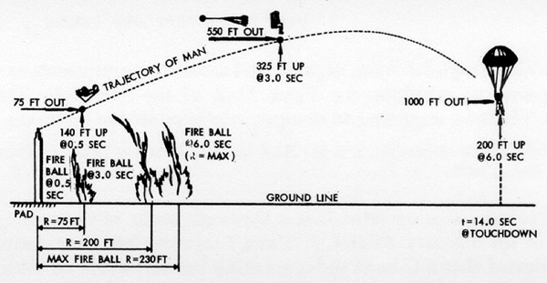 |
| Figure 34. The "off-the-pad" escape mode for an aborted Gemini mission. (Charts presented by K. Hecht, "Project Gemini Familiarization Briefing," July 9-10, 1962, unpaged.) |
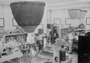 |
| Figure 35. Airborne systems functional test stand at Martin's Baltimore plant. (Martin, Gemini-Titan II Air Force Launch Vehicle, Press Handbook, Feb. 2, 1967, p. 4-3.) |
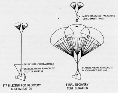 |
| Figure 36. The emergency parachute recovery system for the full-scale paraglider flight test vehicle. (North American Aviation, Inc., Space and Information Systems Division, Paraglider Projects, "Midterm Progress Report, Paraglider Development Program, Phase II, Part A, System Research and Development," SID 62-391, Apr. 20, 1962.) |
 |
| Figure 37. Two McDonnell technicians examine the engineering mockup of the Gemini spacecraft, exhibited to 140 industry and NASA representatives in St. Louis on August 15-16, 1962. (McDonnell Photo D4E-257884, no date.) |
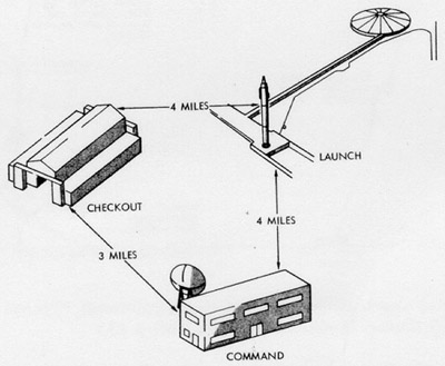 |
| Figure 38. Proposed layout of Gemini facilities at Cape Canaveral. (McDonnell, "Project Gemini Engineering Mockup Review," Aug. 15-16, 1962, p. 163.) |
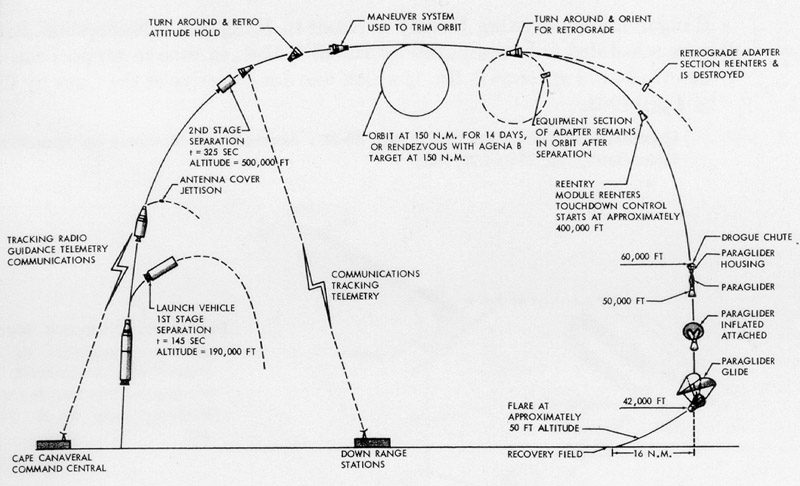
| Figure 39. Planned sequence of events for a Gemini mission. (McDonnell, "Project Gemini Engineering Mockup Review," Aug. 15-16, 1962, p. 23.) |
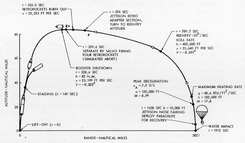
| Figure 40. McDonnell's proposed sequence of events for the first Gemini mission. (McDonnell, "Project Gemini Mission Plan, Spacecraft No. 1," Sept. 14, 1962, p. 7.) |
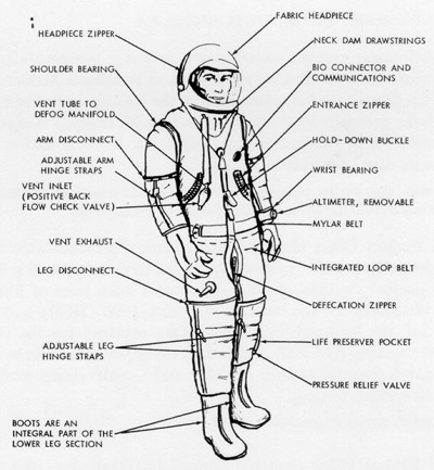 |
| Figure 41. The B. F. Goodrich partial-wear full-pressure suit being developed for the Gemini program. (B. F. Goodrich Aerospace and Defense Products, "Design, Development, and Fabrication of Prototype Pressure Suits, Final Report," Feb. 1, 1965, p. 10.) |
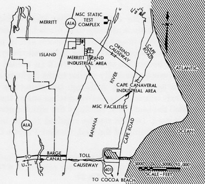 |
| Figure 42. Location of Manned Spacecraft Center facilities at Cape Canaveral and Merritt Island. (NASA, "Manned Spacecraft Center Atlantic Missile Range Operations, 1959-1964 Facilities," Apr. 15, 1963.) |
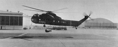 |
| Figure 43. Gemini paraglider half-scale test vehicle slung beneath an Army helicopter at the beginning of the second deployment flight test. (NAA-SID Photo 277/4, Jan. 4, 1963.) |
 |
| Figure 44. The 10-percent model of the Gemini spacecraft used in wind tunnel testing at McDonnell. (McDonnell Photo D4E-250564, undated.) |


