
| Journal Home Page | Apollo 17 Journal |
LM-12 (Challenger)
Cabin Close Out Photos
Scans by Paul Fjeld from NASA negatives
provided by the Northrup Grumman History Center.
Last revised 9 July 2012.
Environmental Control System
(ECS): see, also, LM News Reference Chapter 6 (18 Mb)
Forward
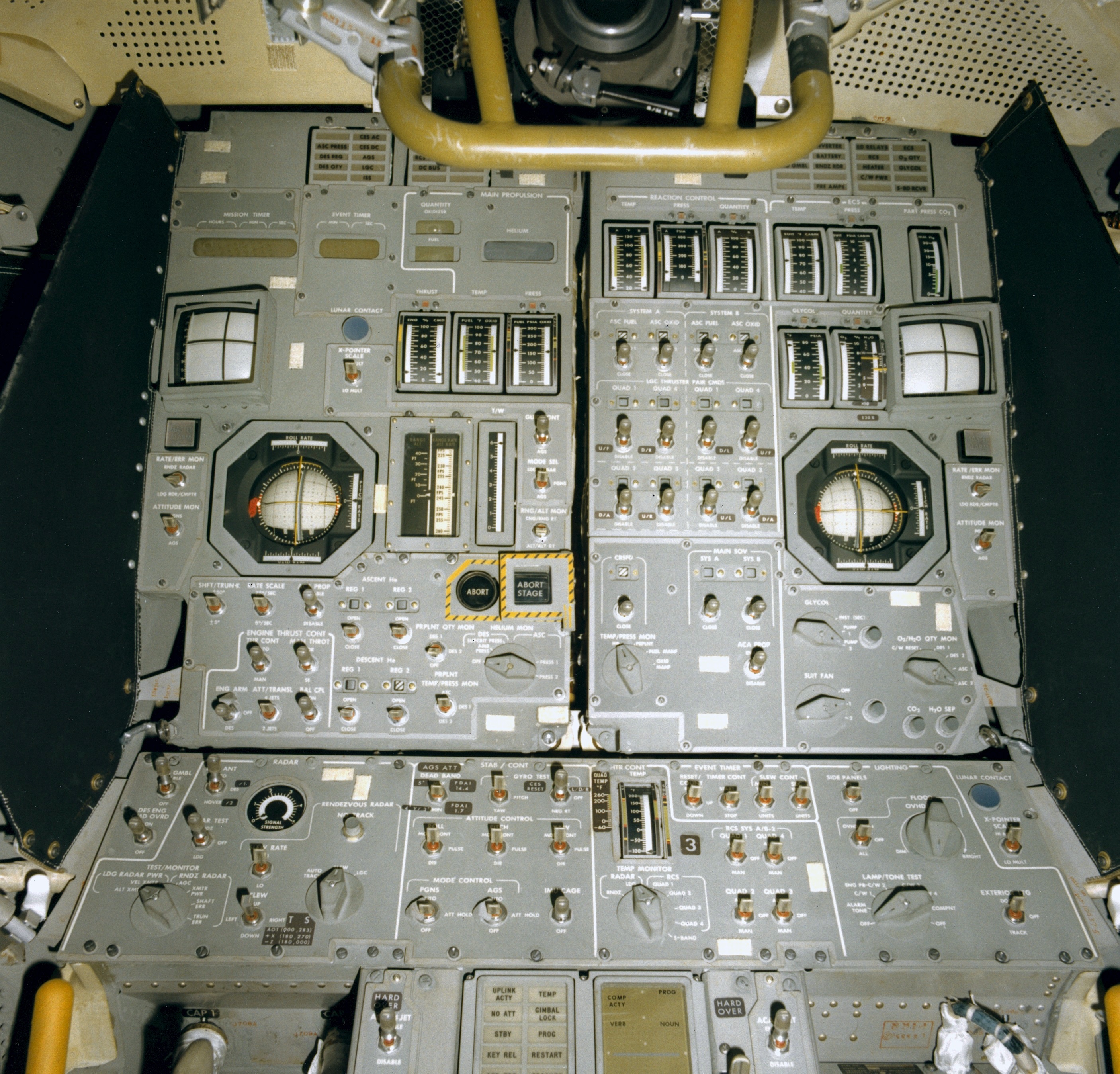
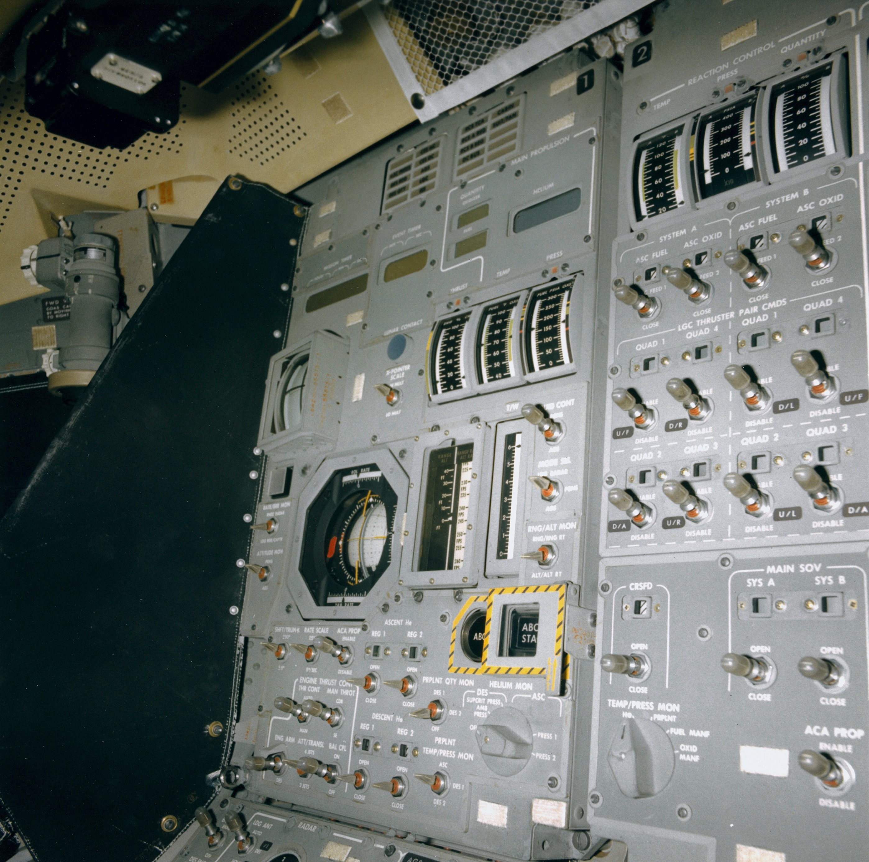
(1) Panel 1 (left), Panel 2 (right), Panel 3 (below both) (2.1 Mb)
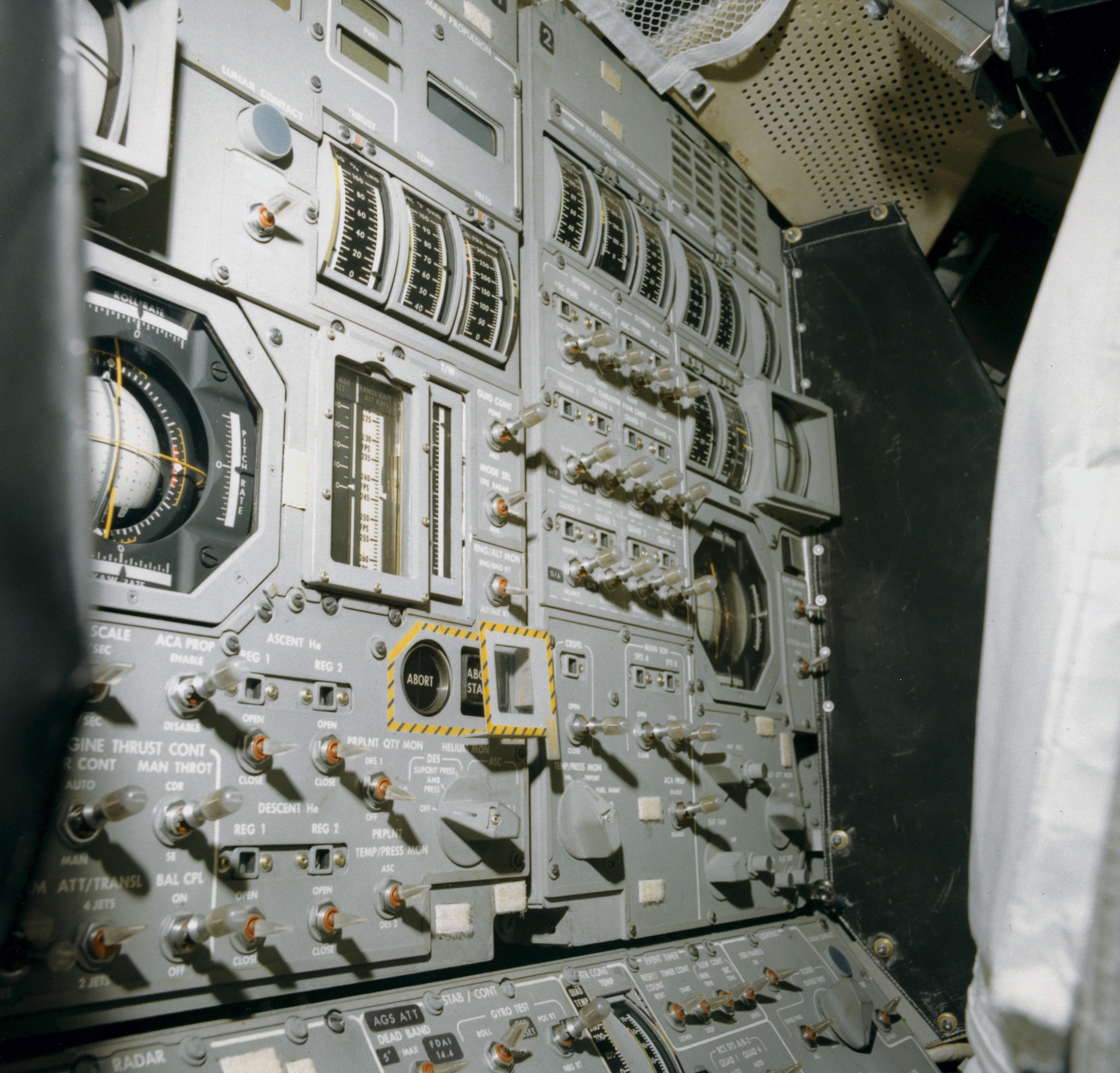
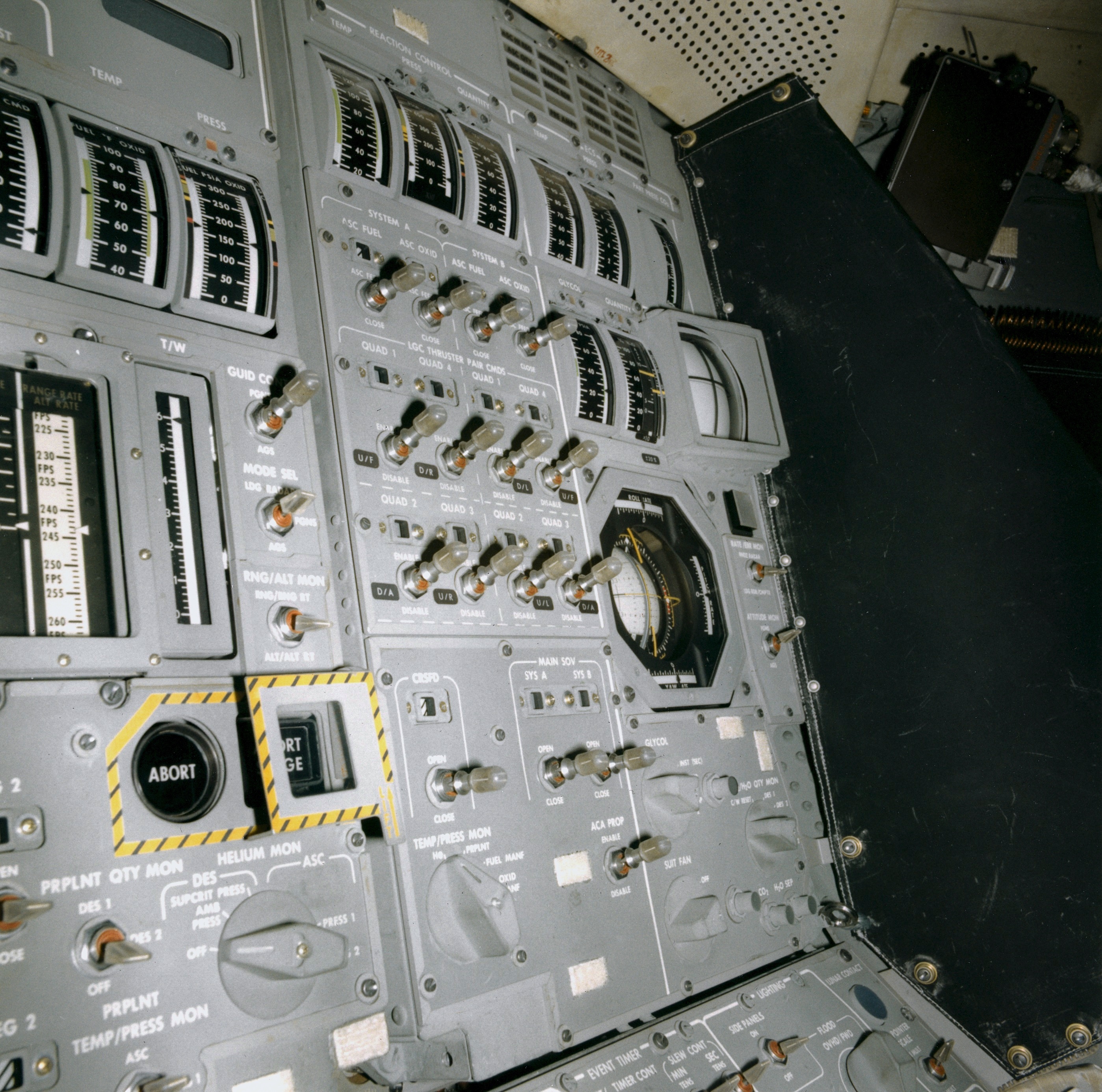
(2) Panel 1 (left), Panel 2 (right), oblique view from the left (1.9 Mb)
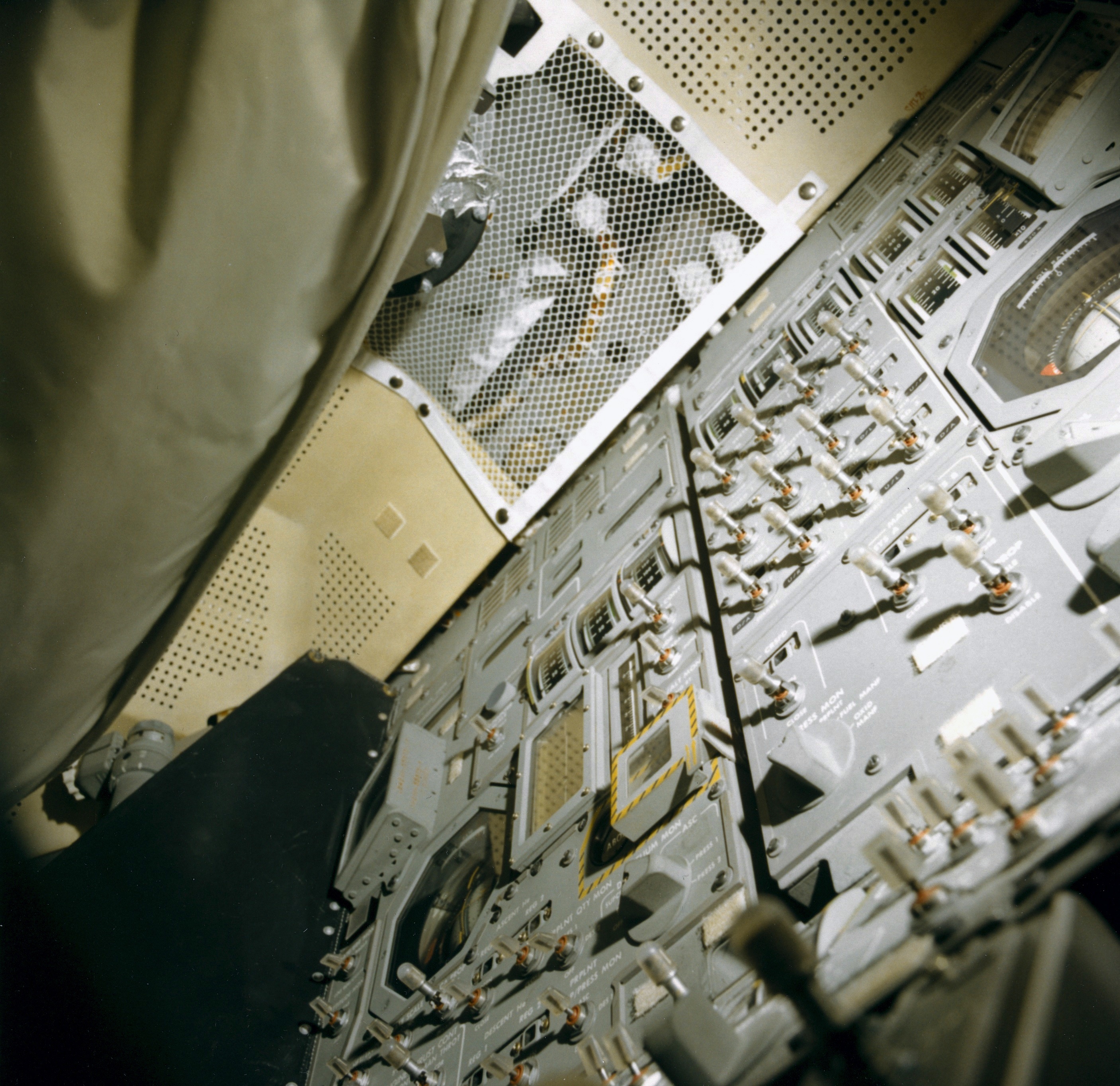
(3) Panel 1, view from below at a steep angle (1.9 Mb)
(4) Panel 1 (left) and the lefthand side of Panel 2 and Panel 3; light shield on the window side of Panel 1 (2.0 Mb)
(5) Panel 2, view up from the left (2.1 Mb)
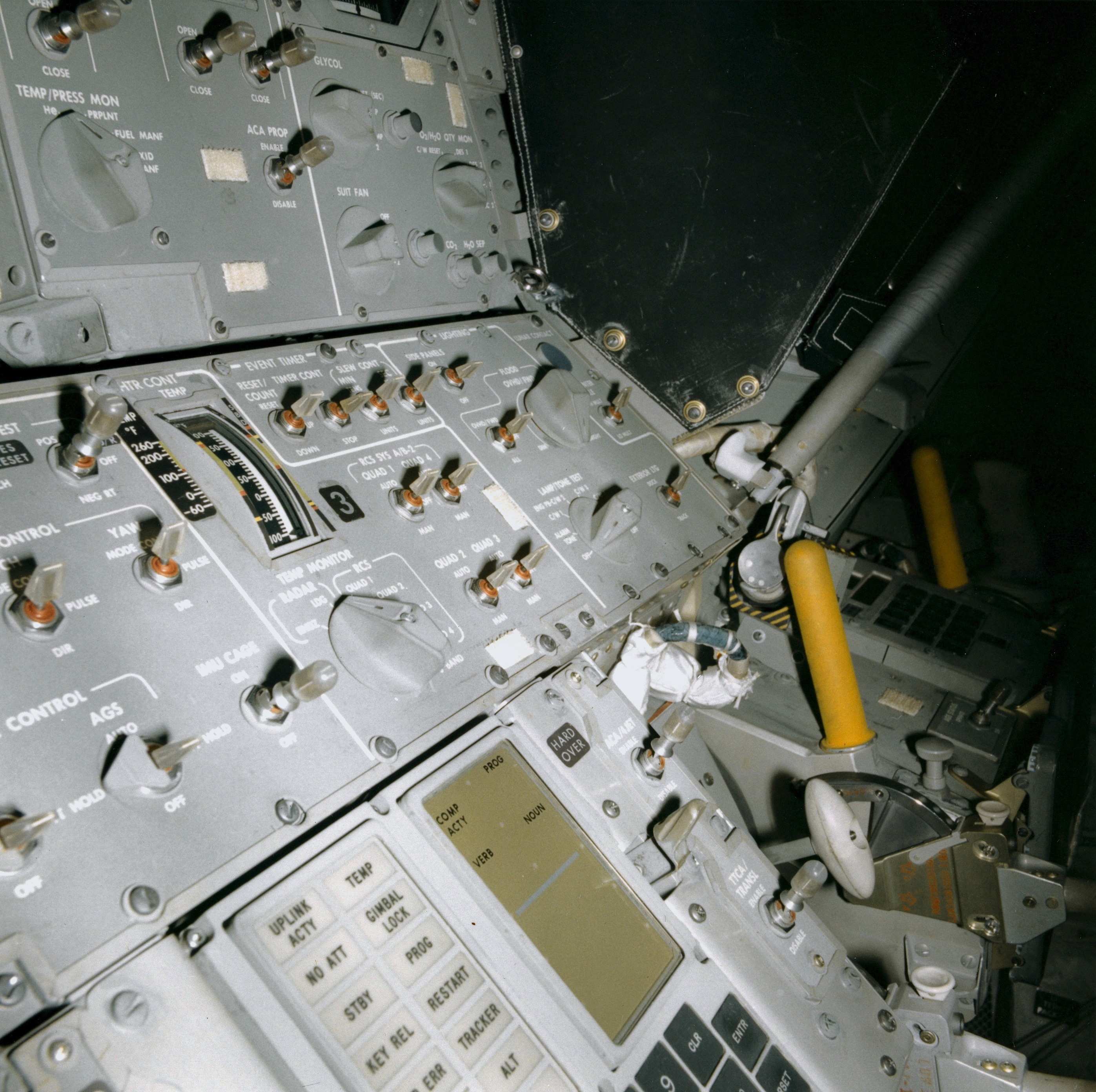
(6) Panel 3 righhand end, lower part of the Panel 2 light shield (2,1 Mb)
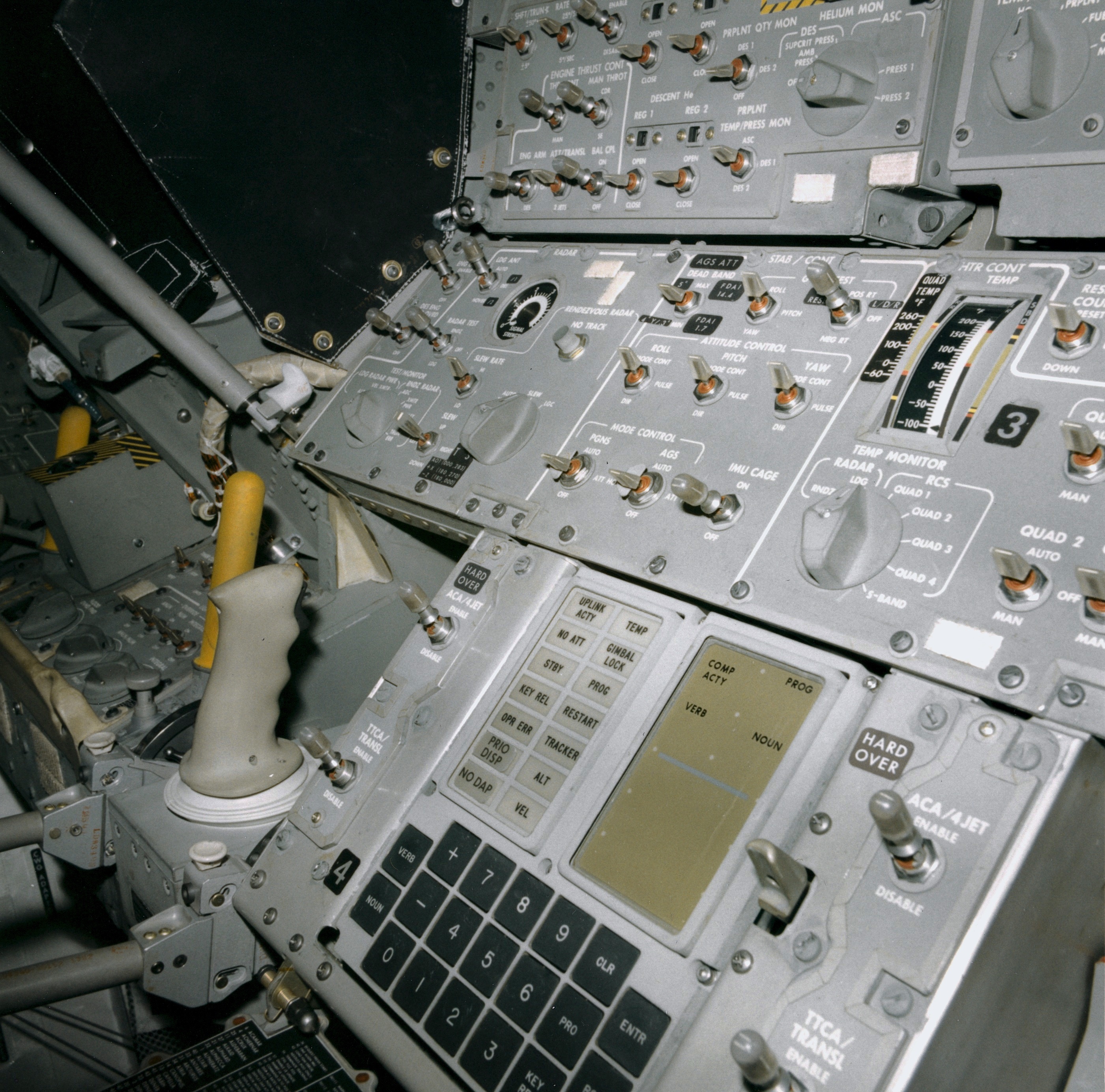
(7) Panel 3 lefthand end, CDR Attitude Controller, DSKY (2.1 Mb)
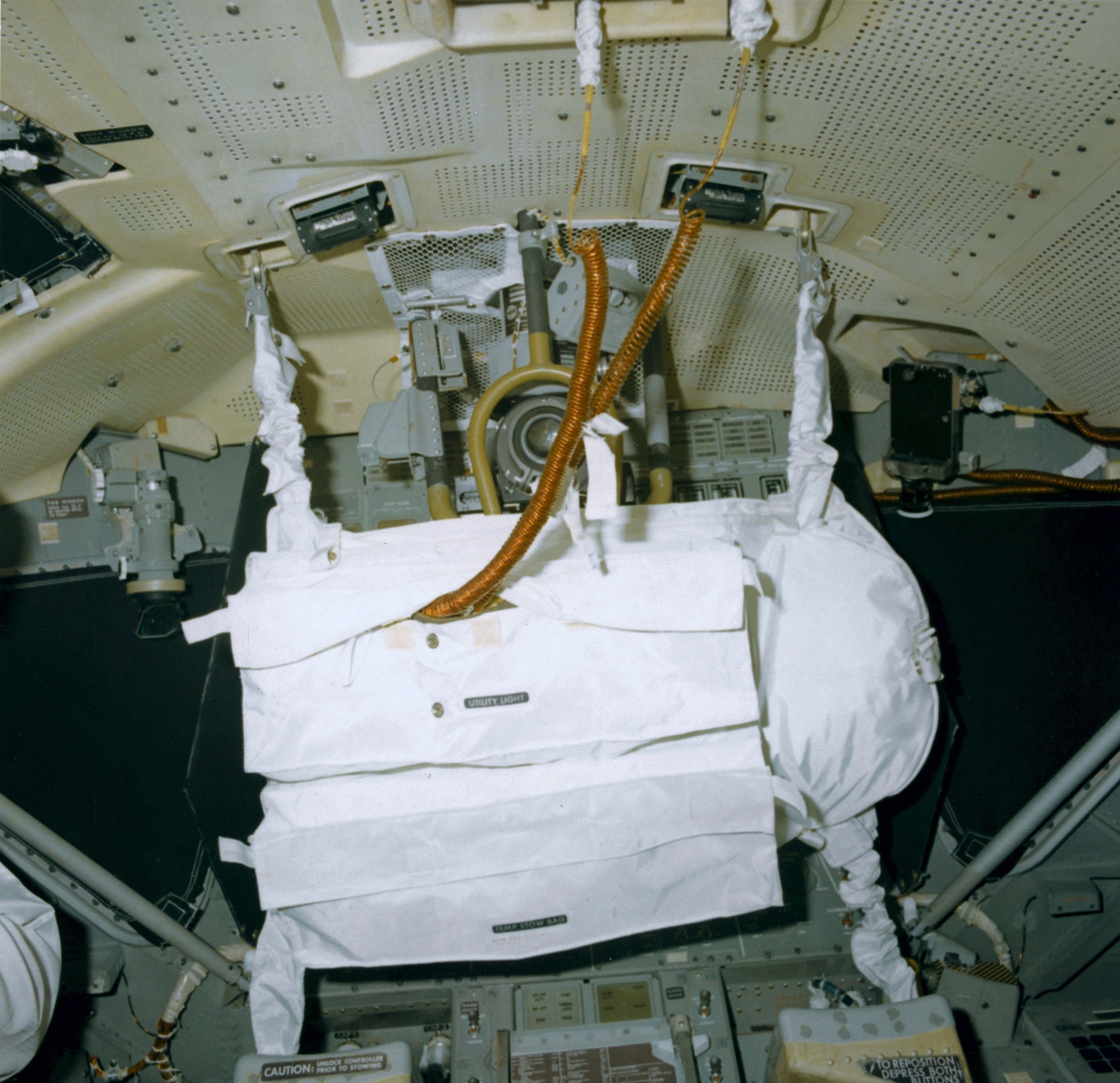
(8) Alignment Optical Telescope (AOT); COAS mounted over the CDR window (left); 16-mm DAC mounted over LMP window (right); Main Panel and Cabin Floodlights in ceiling recesses on the left and right of the AOT; Interim Stowage Assembly (ISA) hanging from the ceiling. (1.8 Mb)
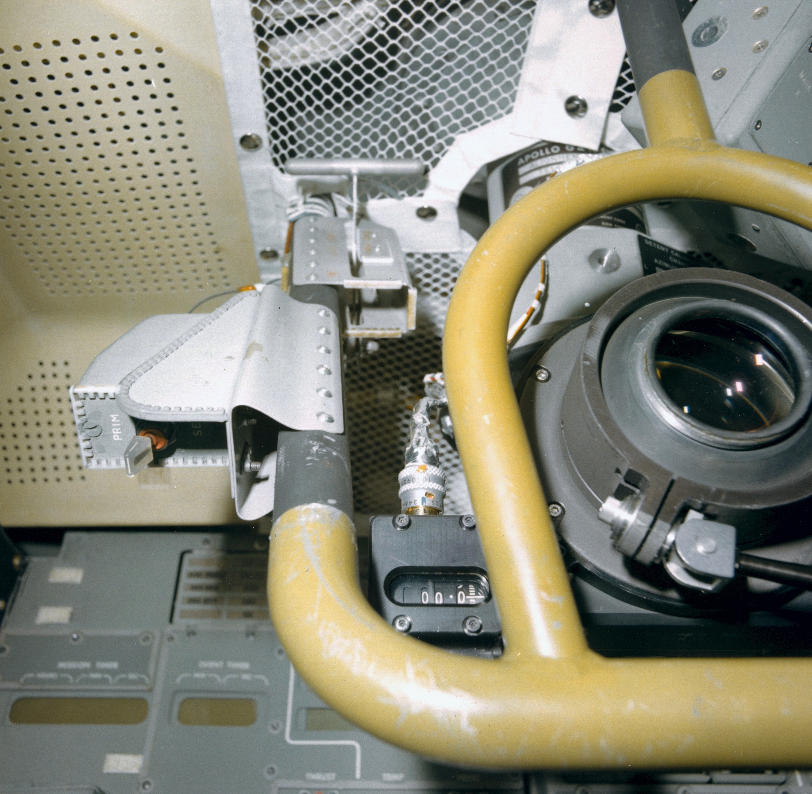
(9) AOT lefthand details (1.9 Mb)
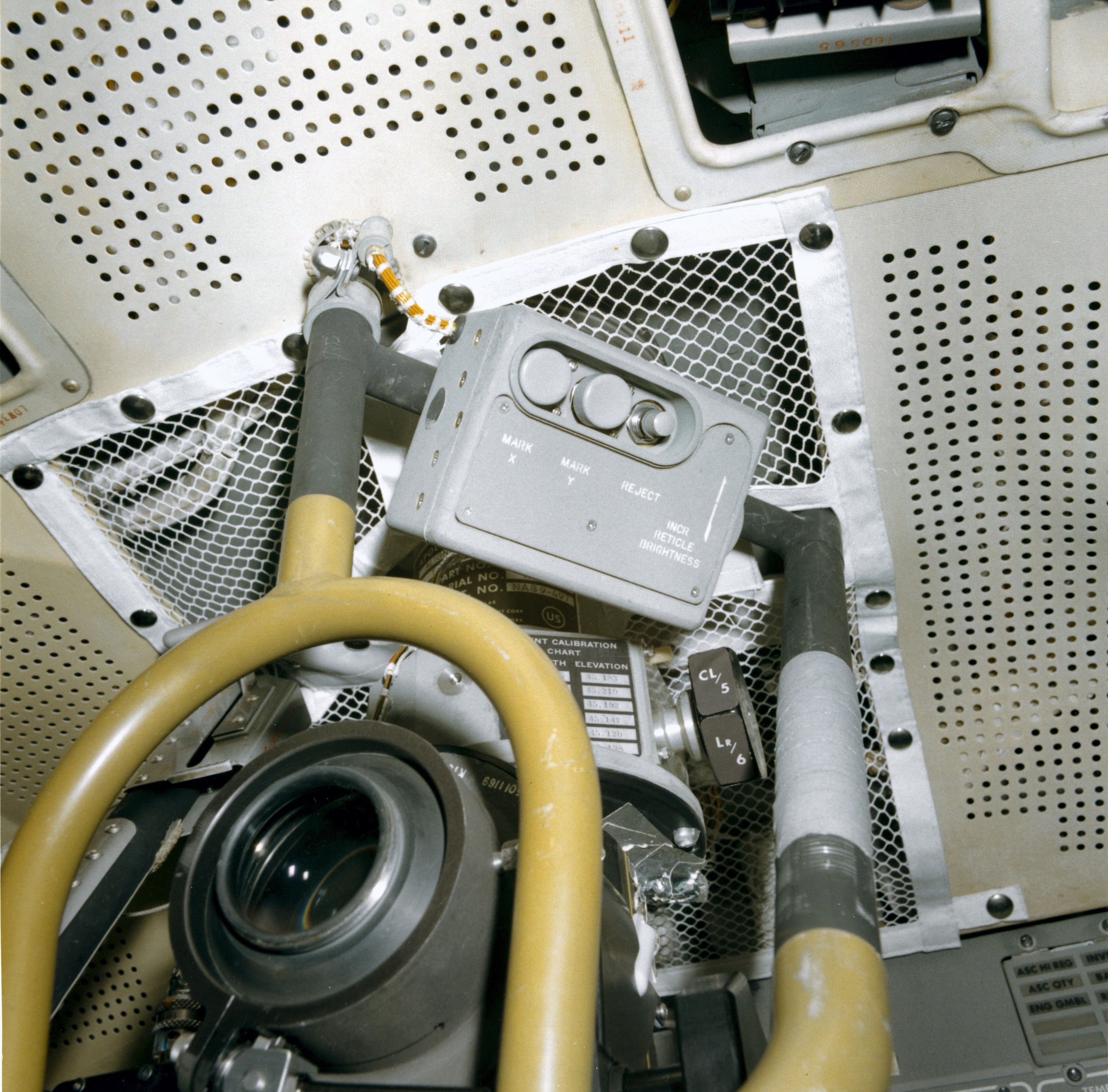
(10) AOT righthand details (2.1 Mb)
CDR Instrument Panels: see, also, LM News Reference Chapter 7 (3.4 Mb)
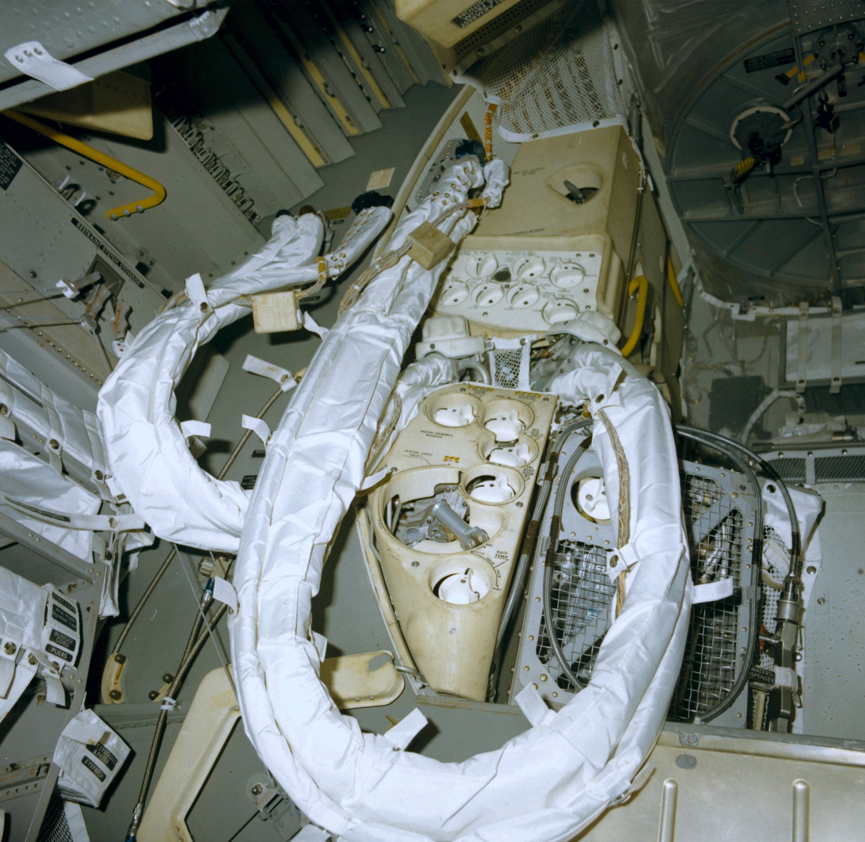
(1) Forward face of the
ECS, view upward, apparently from the hatch (1.9 Mb)
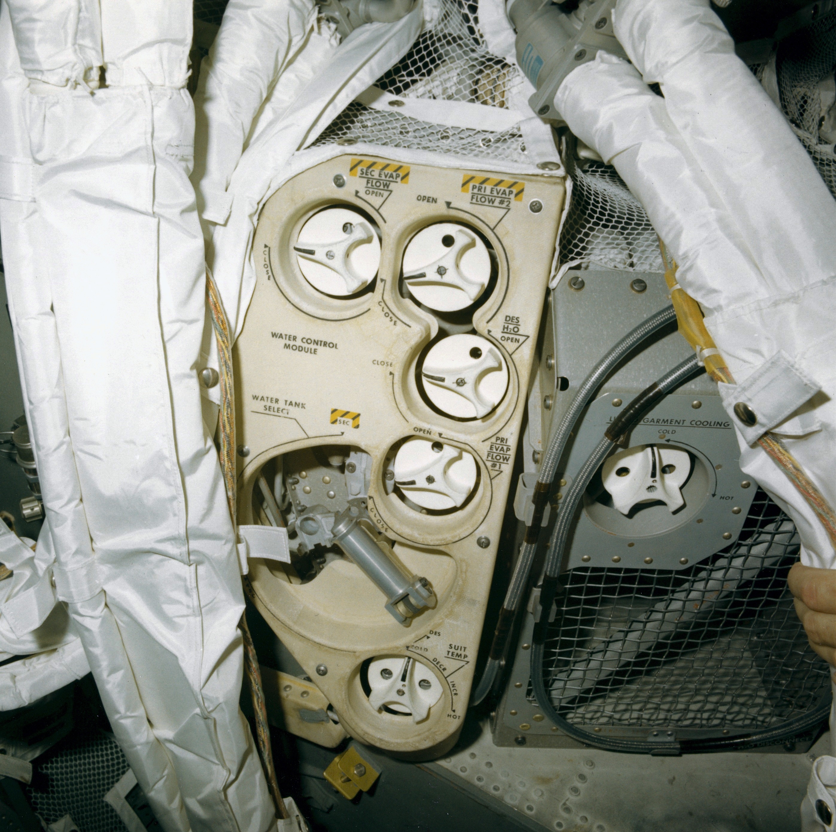
(2) Water Management / LCG Temperature Controls (2.0 Mb)
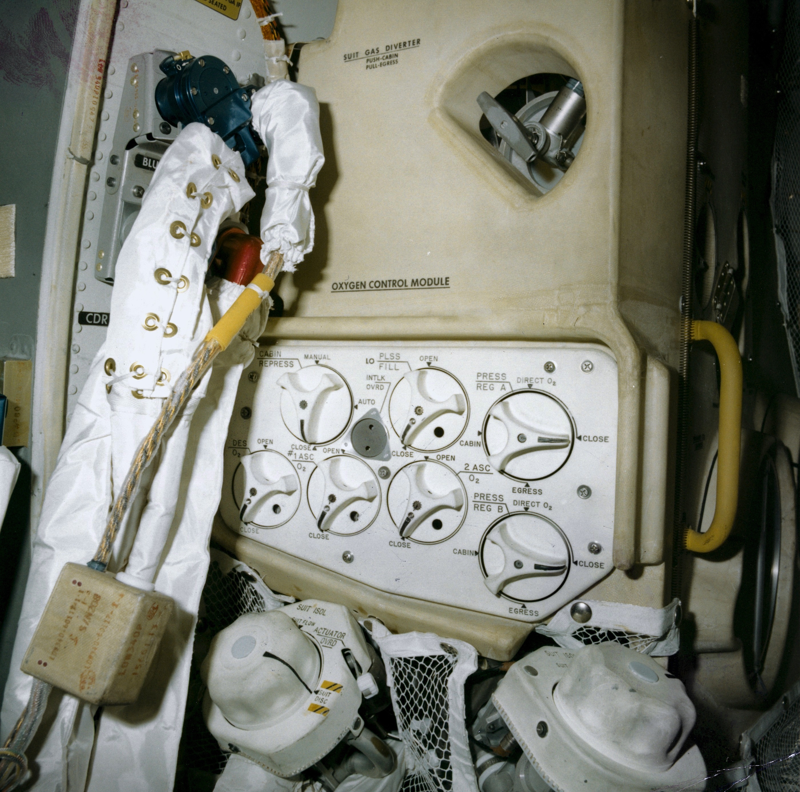
(3) Oxygen Control Module, Suit Gas Diverter, Suit Isolation (right). LMP oxygen hoses: O2 flow from ECS (blue connector), O2 return flow to the ECS (red connector). This is the pair closest to Panel 14 on the LMP's side of the cabin. The more complex blue fitting nearer the camera is the MP's water hose, with channels for flow in each direction. On the thin wall section facing the camera and just to the left of the Oxygen control module, the CDR's water hose is at the top below the "caution" label. The red oxygen coupling is visible below it to the right, while the blue oxygen fitting is hidden under the water hose. (2.1 Mb)
(4) Suit Circuit Module: Suit Circuit Relief, Cabin Gas Return, LiOH cannisters (2.2 Mb)
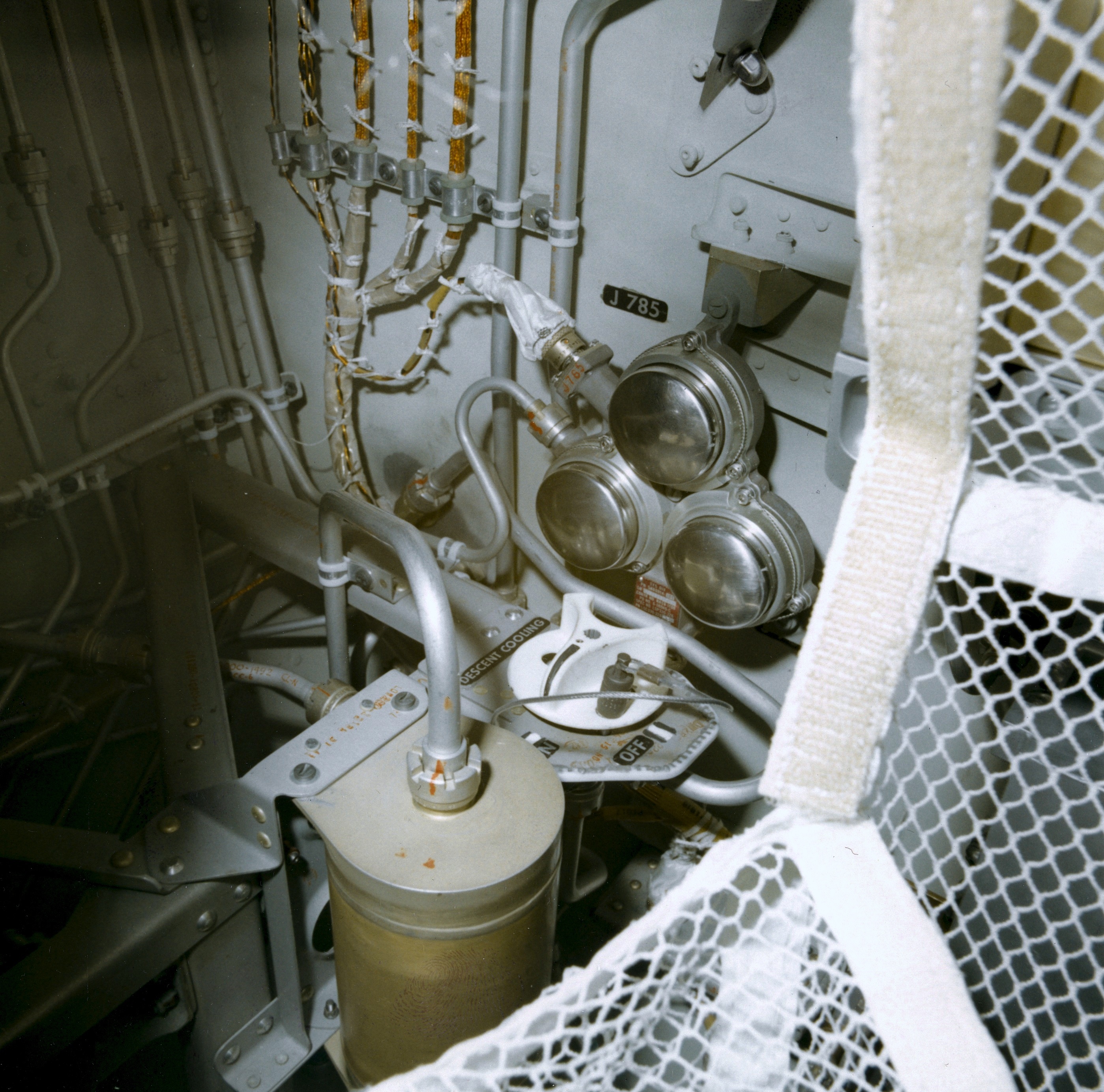
(5) Plumbing aft of the ECS (2.0 Mb)
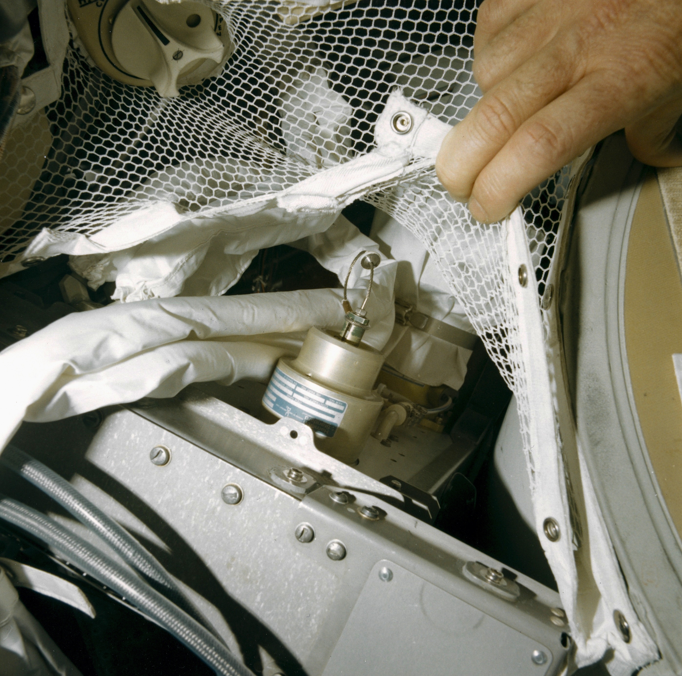
(6) Unidentified ECS detail (2.0 Mb)
(2) Water Management / LCG Temperature Controls (2.0 Mb)
(3) Oxygen Control Module, Suit Gas Diverter, Suit Isolation (right). LMP oxygen hoses: O2 flow from ECS (blue connector), O2 return flow to the ECS (red connector). This is the pair closest to Panel 14 on the LMP's side of the cabin. The more complex blue fitting nearer the camera is the MP's water hose, with channels for flow in each direction. On the thin wall section facing the camera and just to the left of the Oxygen control module, the CDR's water hose is at the top below the "caution" label. The red oxygen coupling is visible below it to the right, while the blue oxygen fitting is hidden under the water hose. (2.1 Mb)
(4) Suit Circuit Module: Suit Circuit Relief, Cabin Gas Return, LiOH cannisters (2.2 Mb)
(5) Plumbing aft of the ECS (2.0 Mb)
(6) Unidentified ECS detail (2.0 Mb)
Forward
(1) Panel 1 (left), Panel 2 (right), Panel 3 (below both) (2.1 Mb)
(2) Panel 1 (left), Panel 2 (right), oblique view from the left (1.9 Mb)
(3) Panel 1, view from below at a steep angle (1.9 Mb)
(4) Panel 1 (left) and the lefthand side of Panel 2 and Panel 3; light shield on the window side of Panel 1 (2.0 Mb)
(5) Panel 2, view up from the left (2.1 Mb)
(6) Panel 3 righhand end, lower part of the Panel 2 light shield (2,1 Mb)
(7) Panel 3 lefthand end, CDR Attitude Controller, DSKY (2.1 Mb)
(8) Alignment Optical Telescope (AOT); COAS mounted over the CDR window (left); 16-mm DAC mounted over LMP window (right); Main Panel and Cabin Floodlights in ceiling recesses on the left and right of the AOT; Interim Stowage Assembly (ISA) hanging from the ceiling. (1.8 Mb)
(9) AOT lefthand details (1.9 Mb)
(10) AOT righthand details (2.1 Mb)
CDR Instrument Panels: see, also, LM News Reference Chapter 7 (3.4 Mb)
(1)
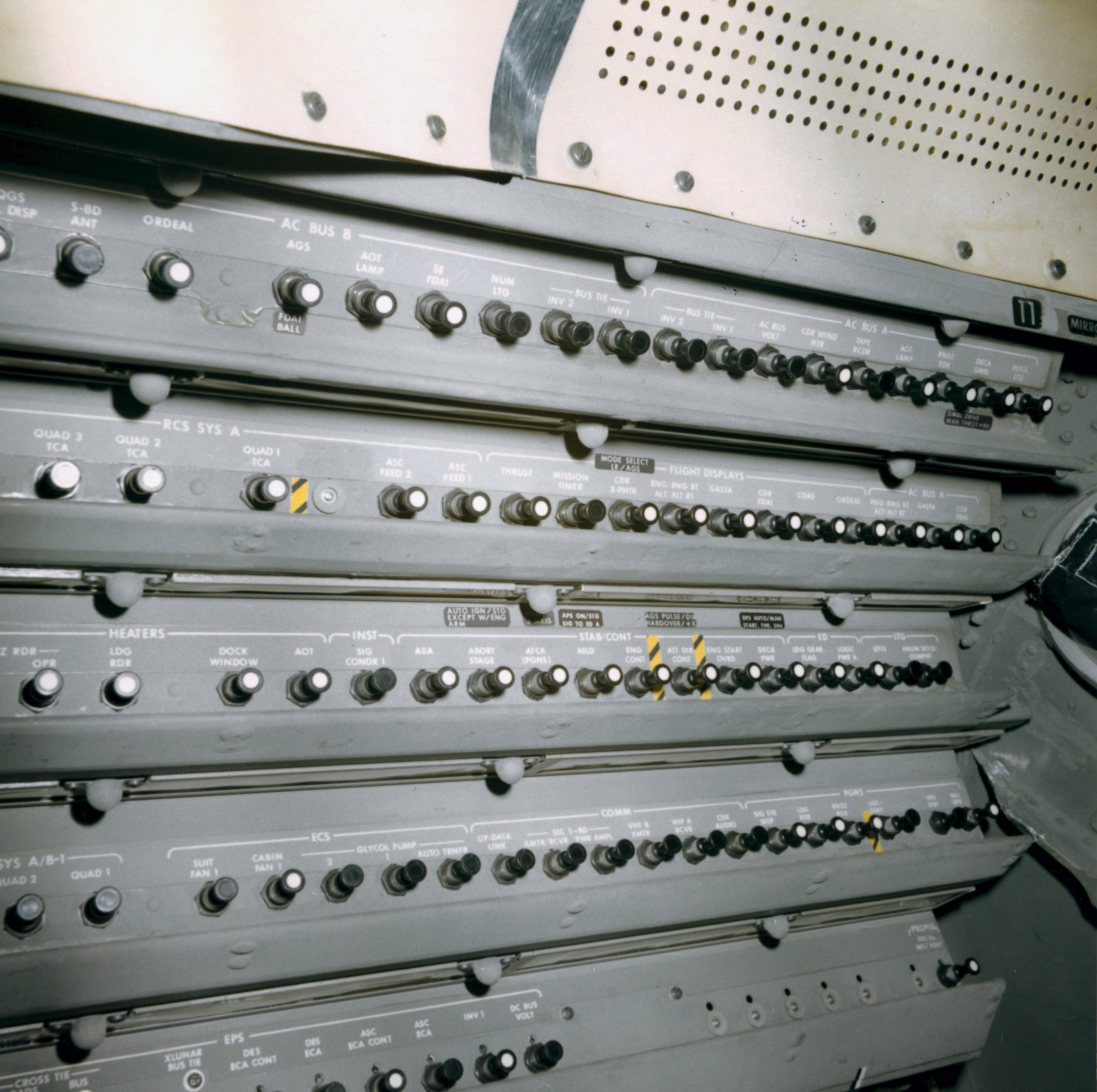
CB(11) CDR Circuit Breaker Panel, aft end (2,0 Mb)
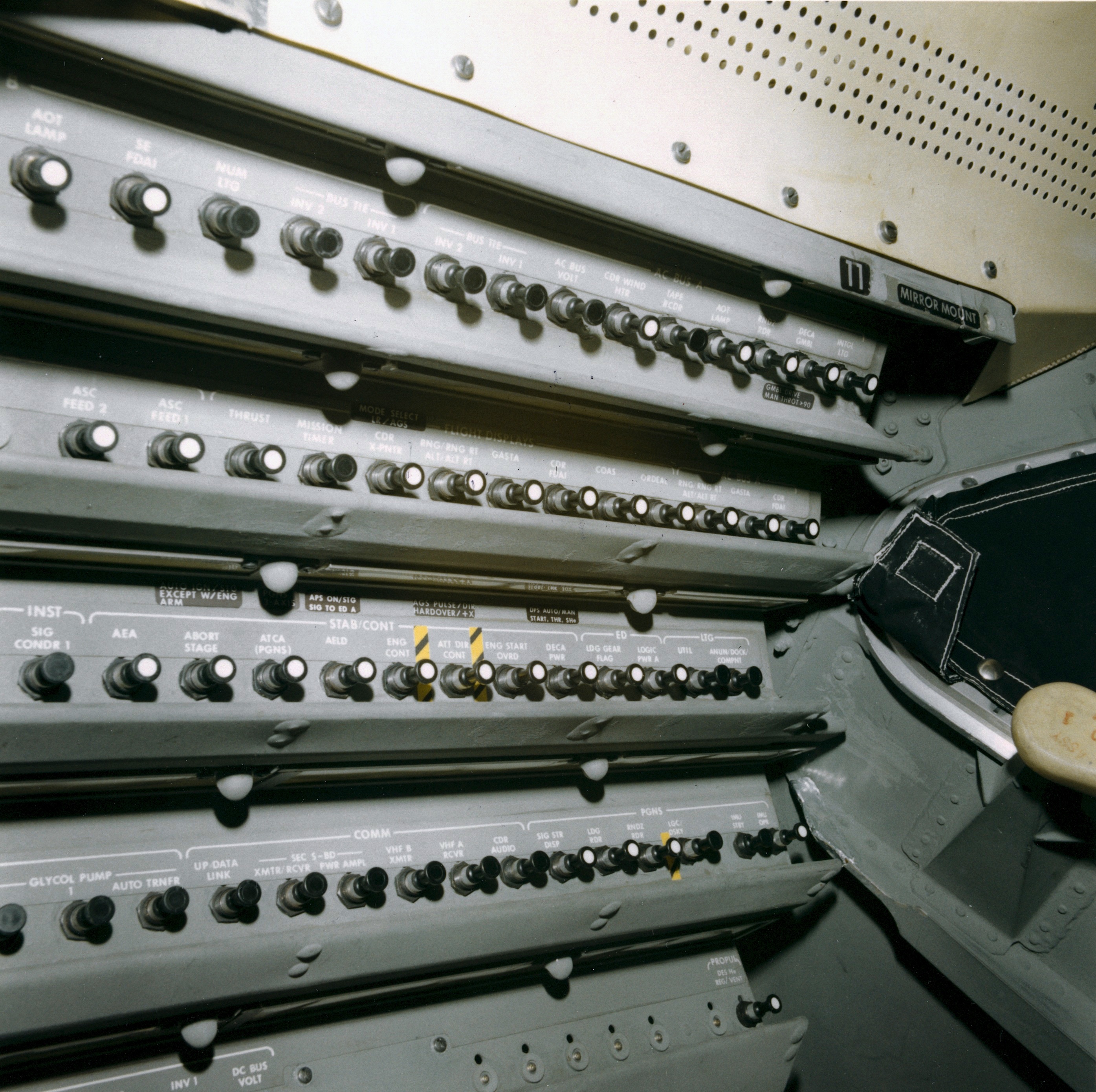
(2) CB(11) CDR Circuit Breaker Panel, forward end, two slightly different views: (1.8 Mb) and (1.9 Mb)
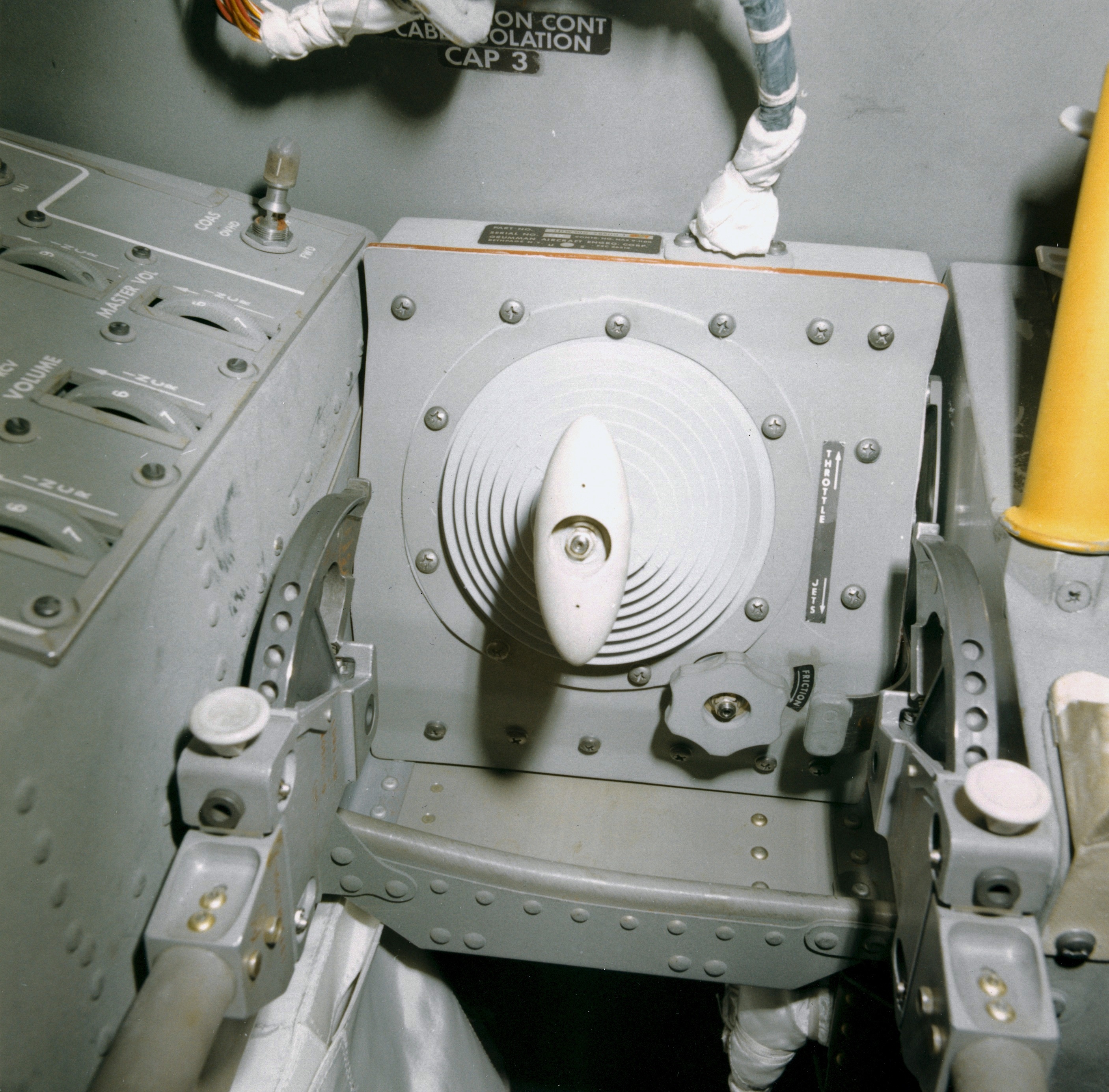
(3) CDR Thrust/Translation Controller Assembly (TTCA) (1.9 Mb)
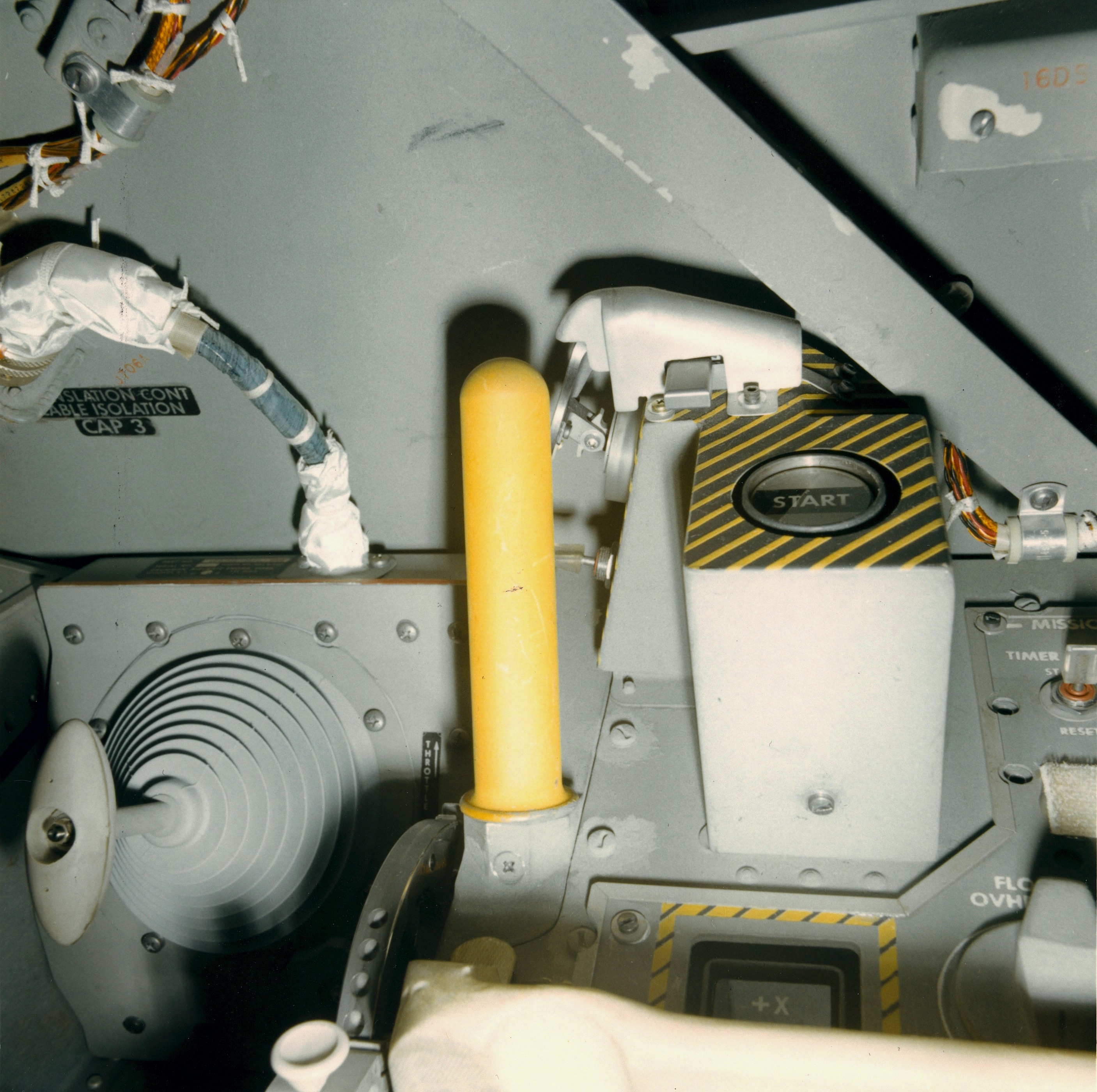
(4) CDR Start/Stop button, hand grip, TTCA (1.8 Mb)
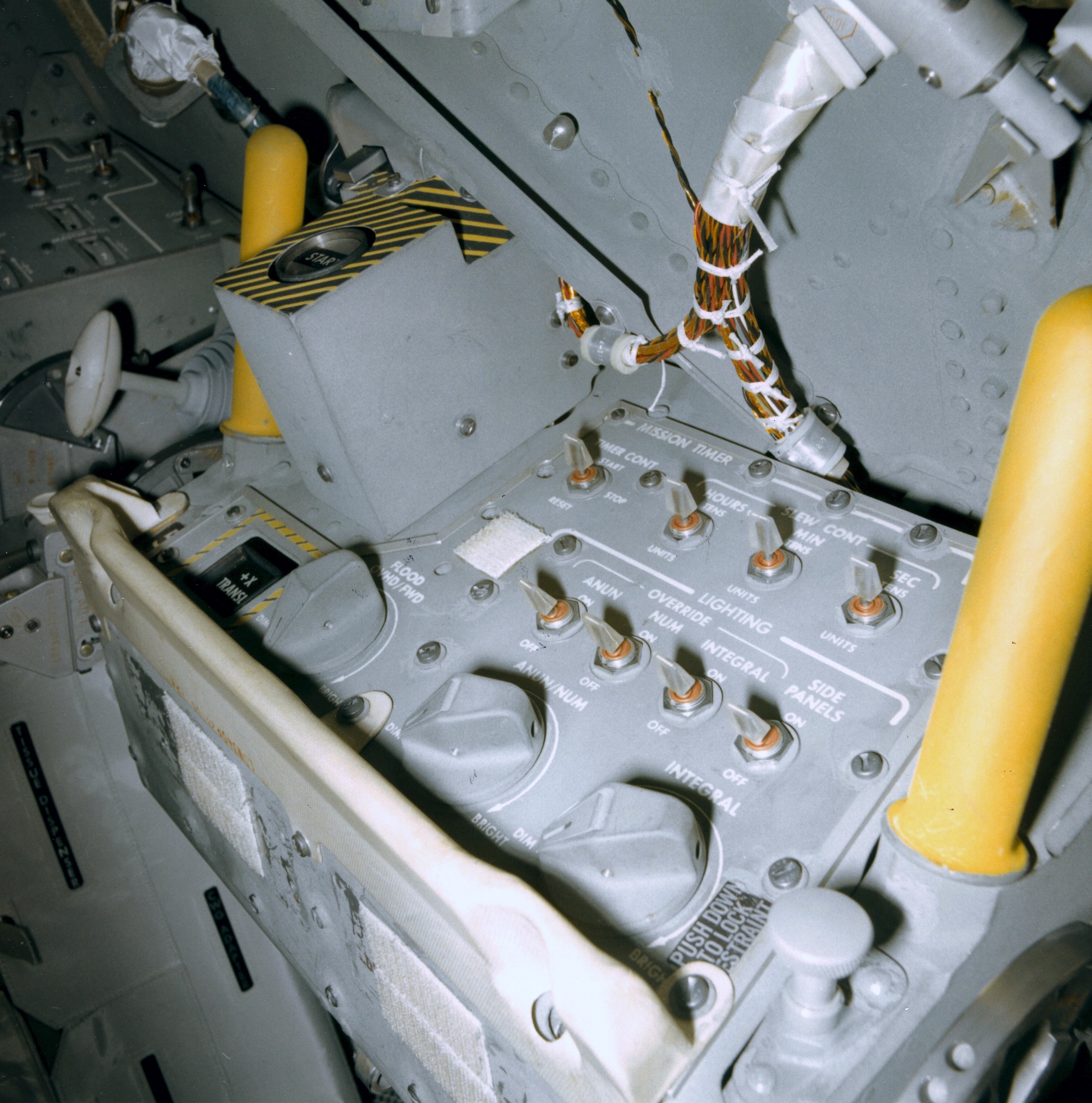
(5) Panel 5, Engine Start/Stop and X-translation push buttons, mission timer/lighting controls (1.9 Mb)
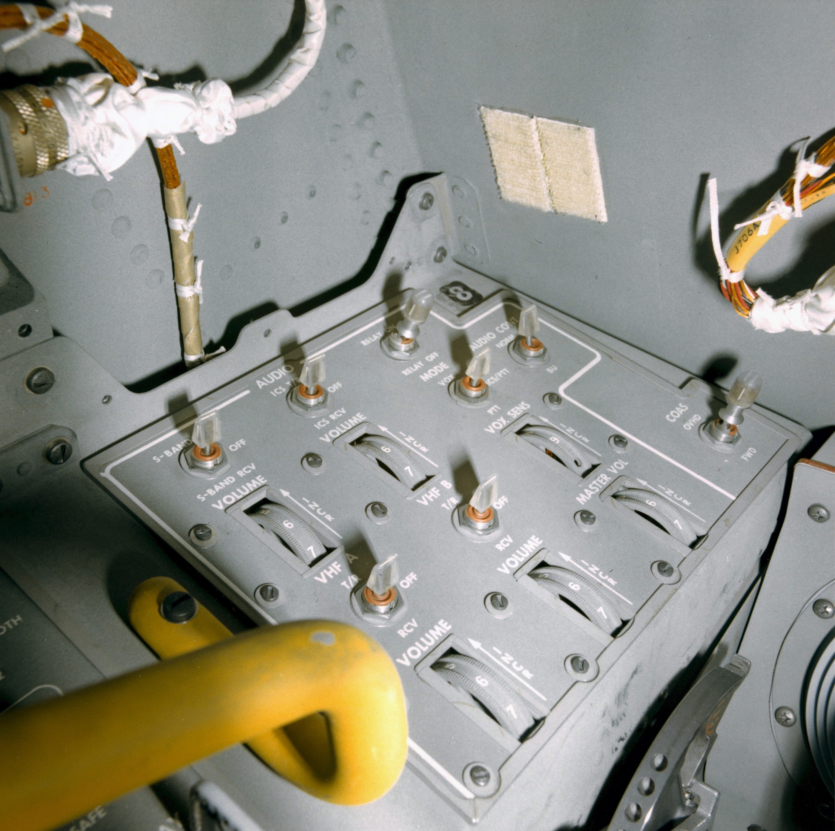
(6) Panel 8 forward section, Audio, COAS switch (2.0 Mb)
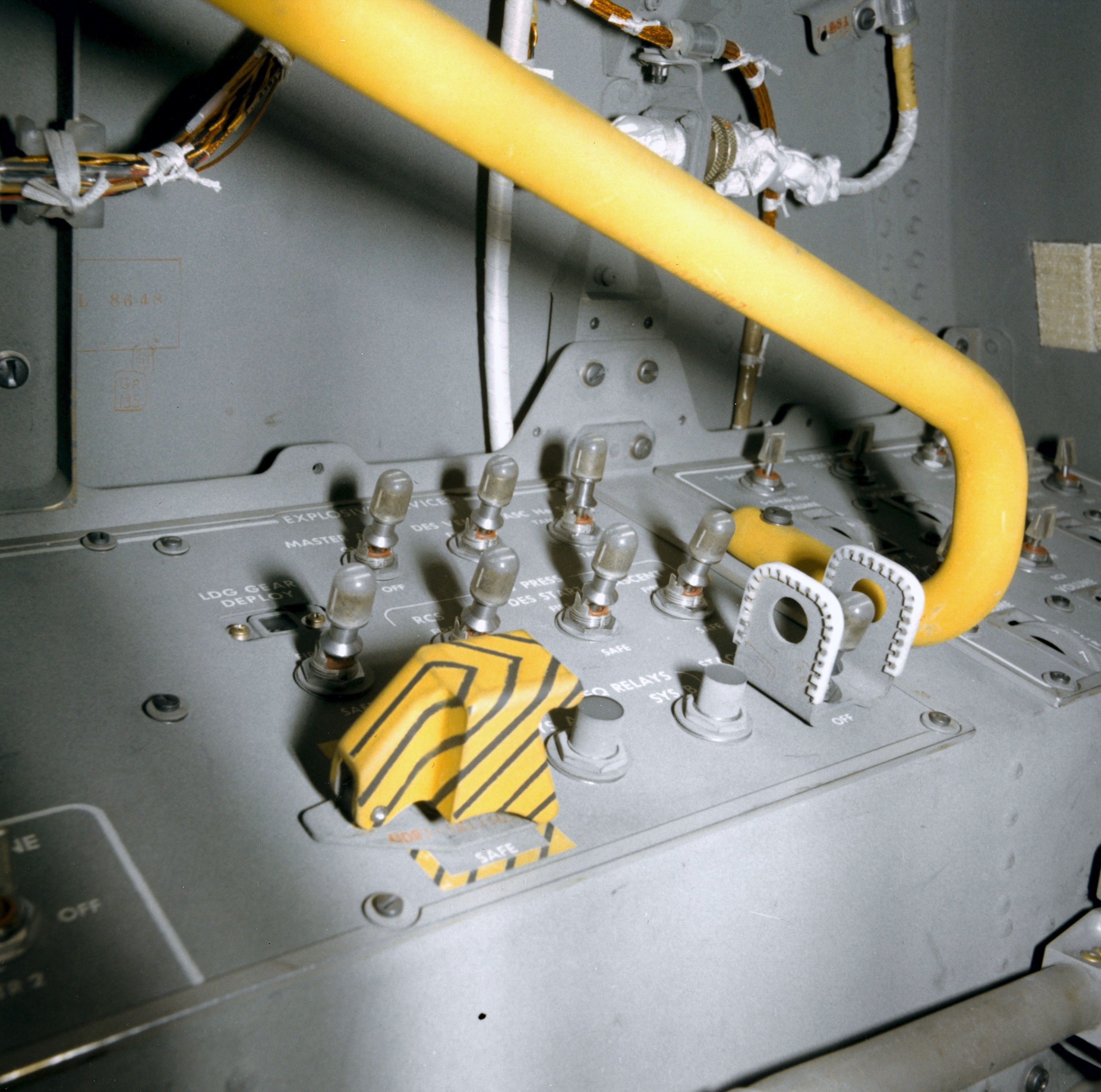
(7) Panel 8 central section, Explosive Device controls (1.8 Mb)
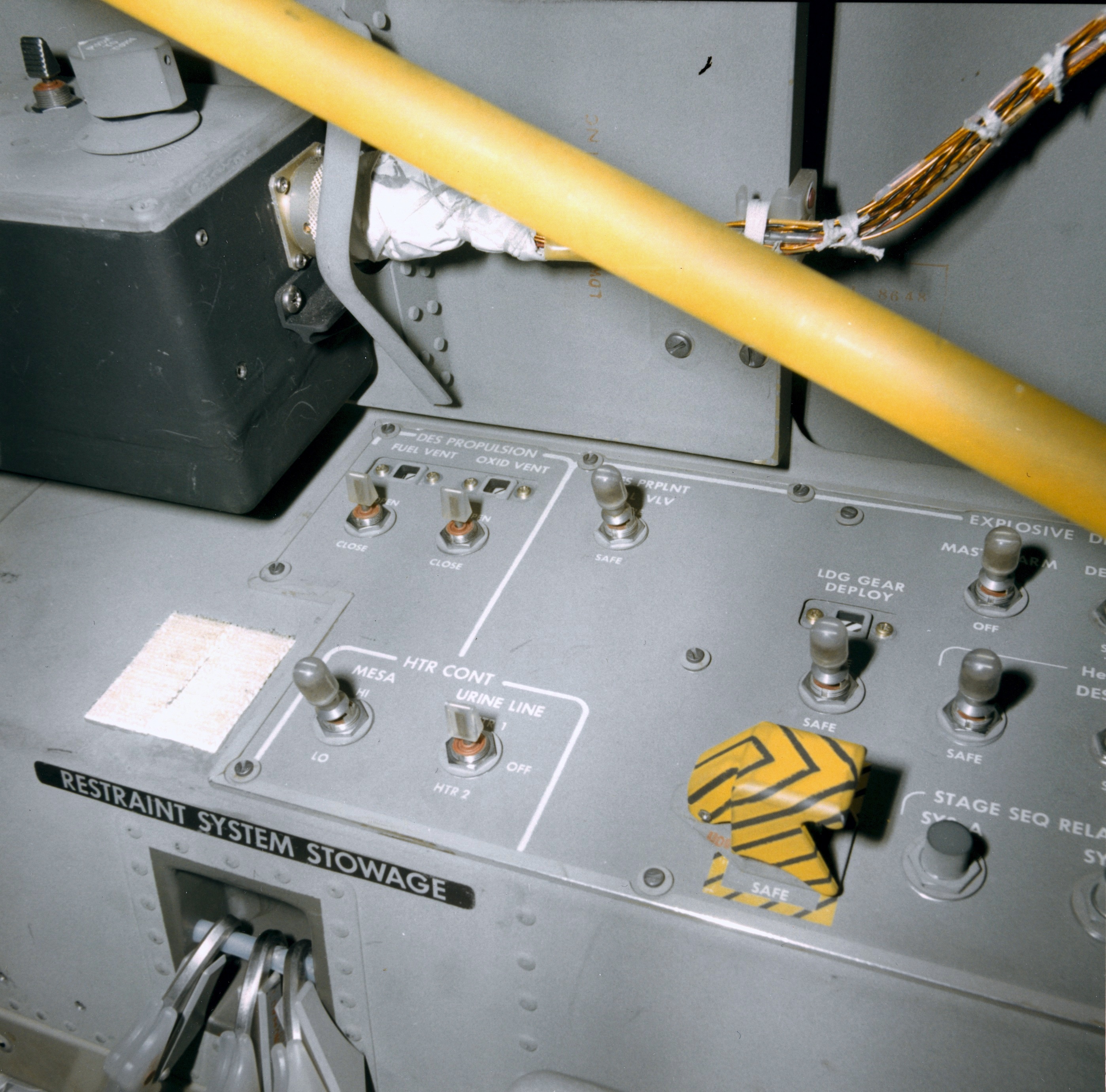
(8) Panel 8 aft end, view from inboard, Descent Propulsion Vent switches, Heater Controls, Explosive Device controls (partial) (1.8 Mb)
(2) CB(11) CDR Circuit Breaker Panel, forward end, two slightly different views: (1.8 Mb) and (1.9 Mb)
(3) CDR Thrust/Translation Controller Assembly (TTCA) (1.9 Mb)
(4) CDR Start/Stop button, hand grip, TTCA (1.8 Mb)
(5) Panel 5, Engine Start/Stop and X-translation push buttons, mission timer/lighting controls (1.9 Mb)
(6) Panel 8 forward section, Audio, COAS switch (2.0 Mb)
(7) Panel 8 central section, Explosive Device controls (1.8 Mb)
(8) Panel 8 aft end, view from inboard, Descent Propulsion Vent switches, Heater Controls, Explosive Device controls (partial) (1.8 Mb)
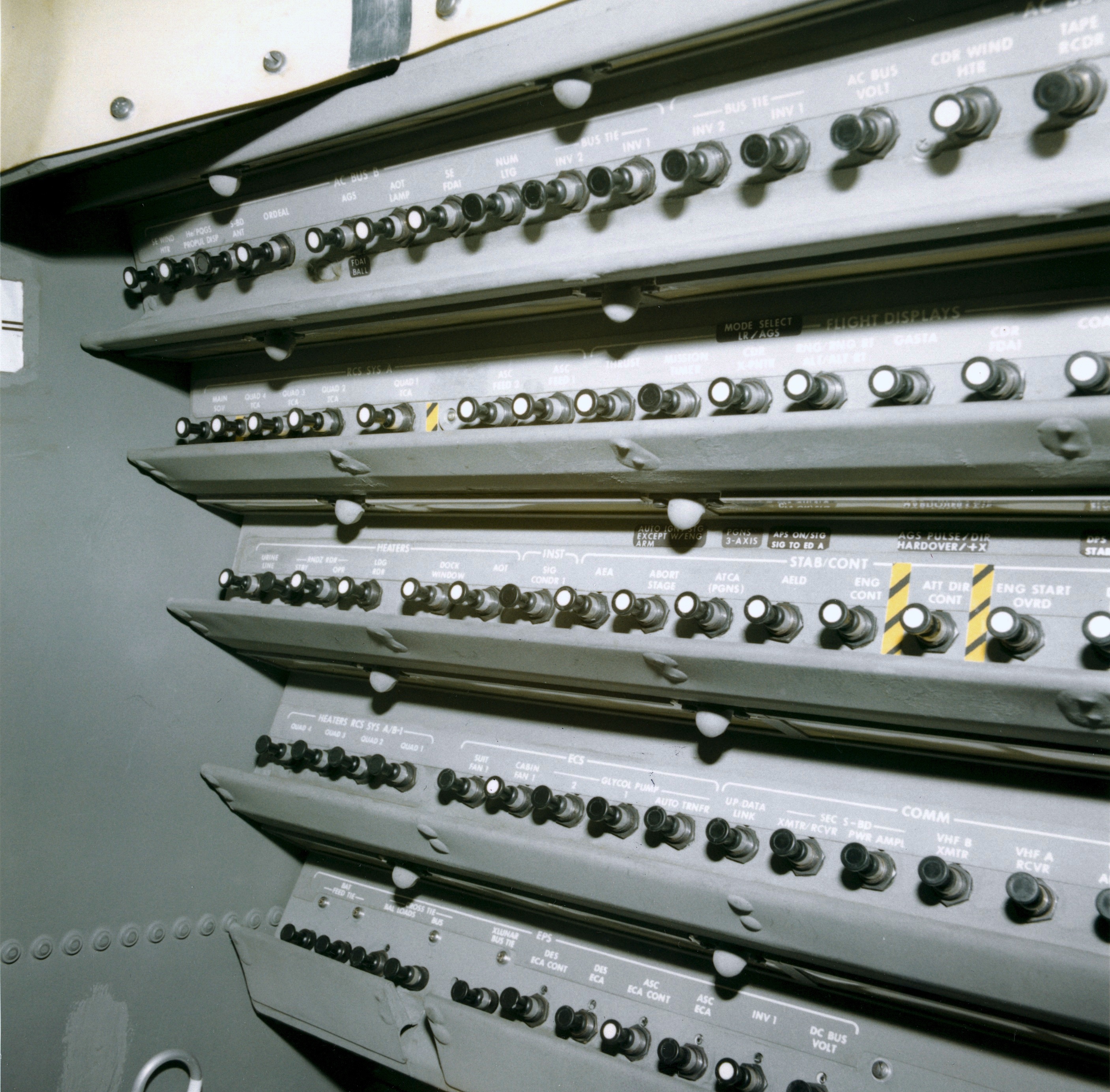
LMP Instrument Panels: see, also, LM News Reference Chapter 7 (3.4 Mb)
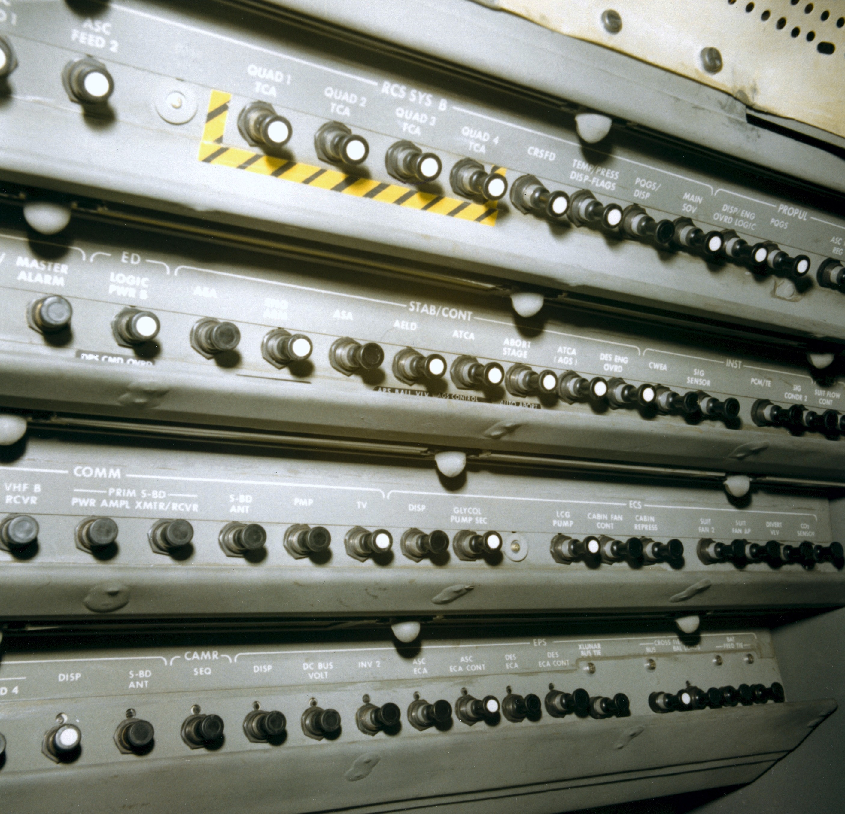
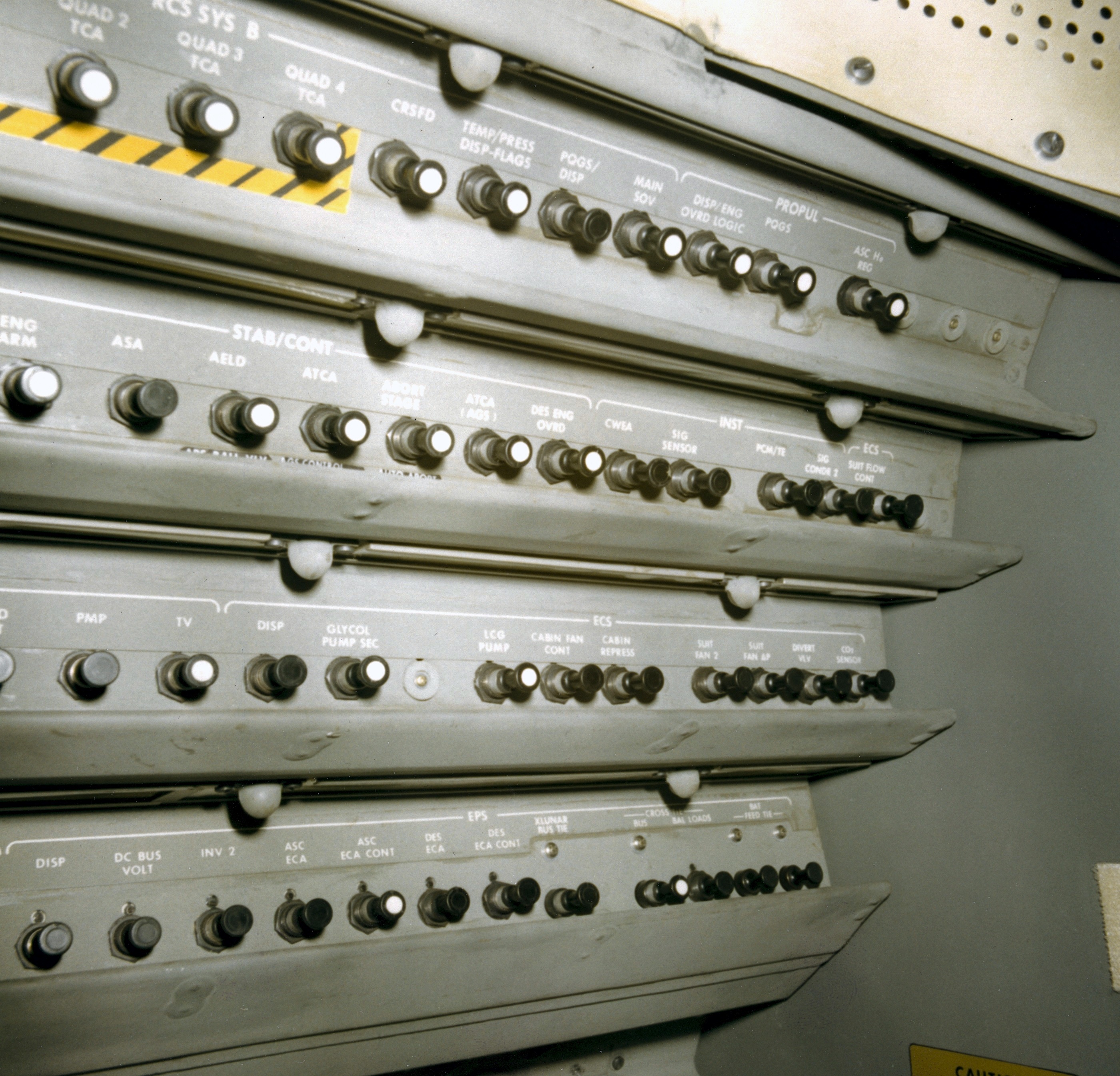
(1) CB(16) LMP Circuit Breaker Panel, aft end, two views (1.8 Mb) and (1.8 Mb)
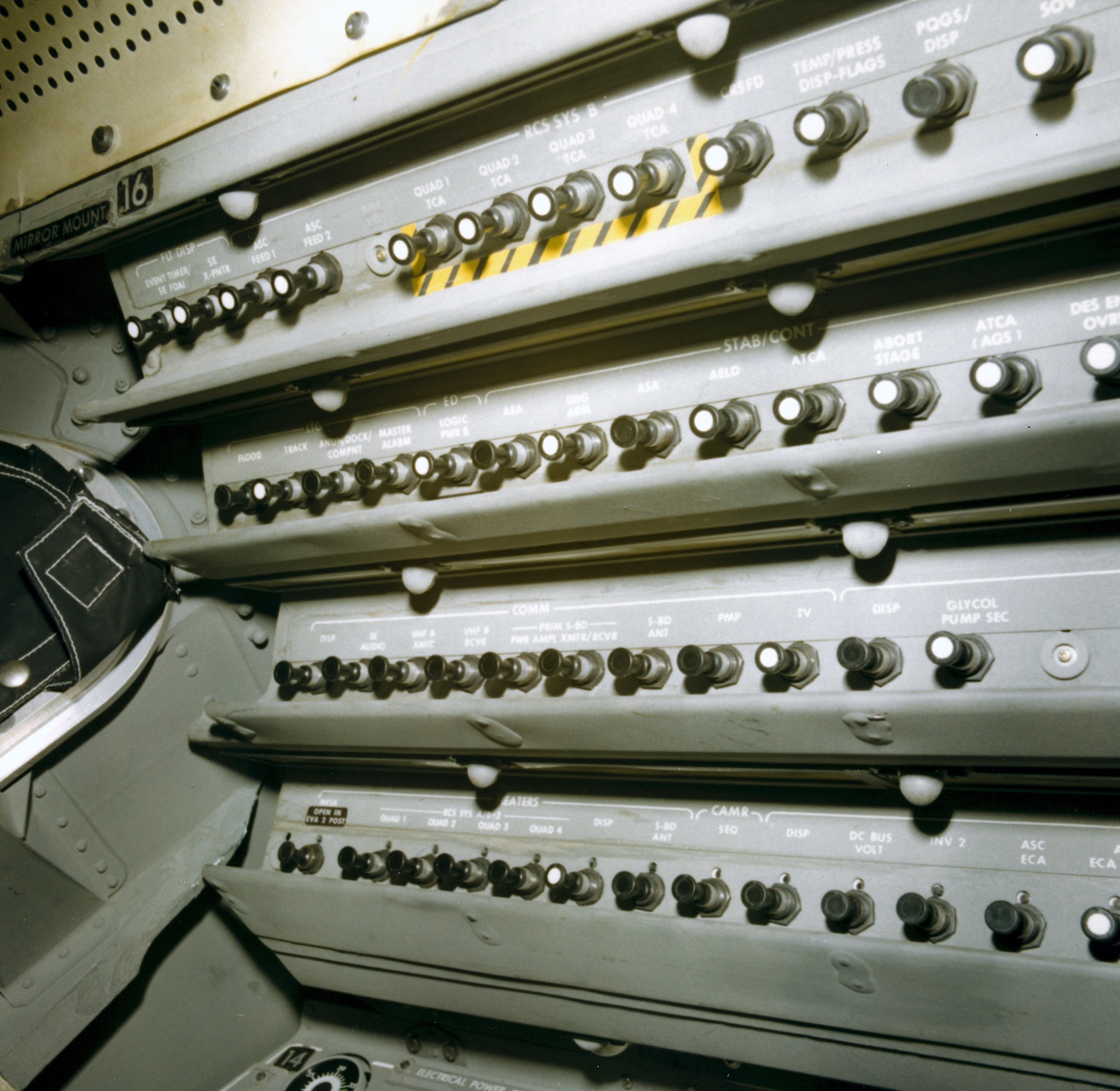
(2) CB(16) LMP Circuit Breaker Panel, forward end (1.8 Mb)
(3) Panel 12, forward section, Audio (1.9 Mb)
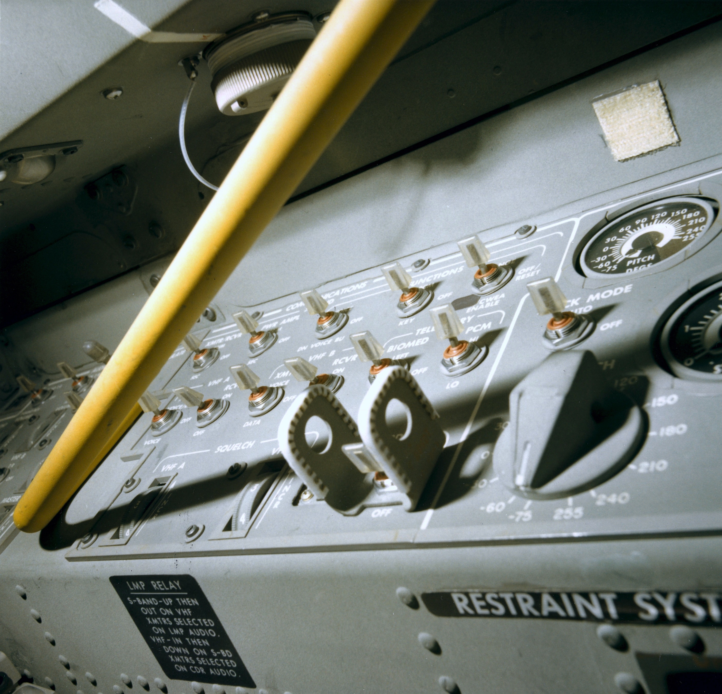
(4) Panel 12, center section, Communications, view from the side and slightly aft (1.8 Mb)
(5) Panel 12, aft section, Communications Antennas (1.9 Mb)
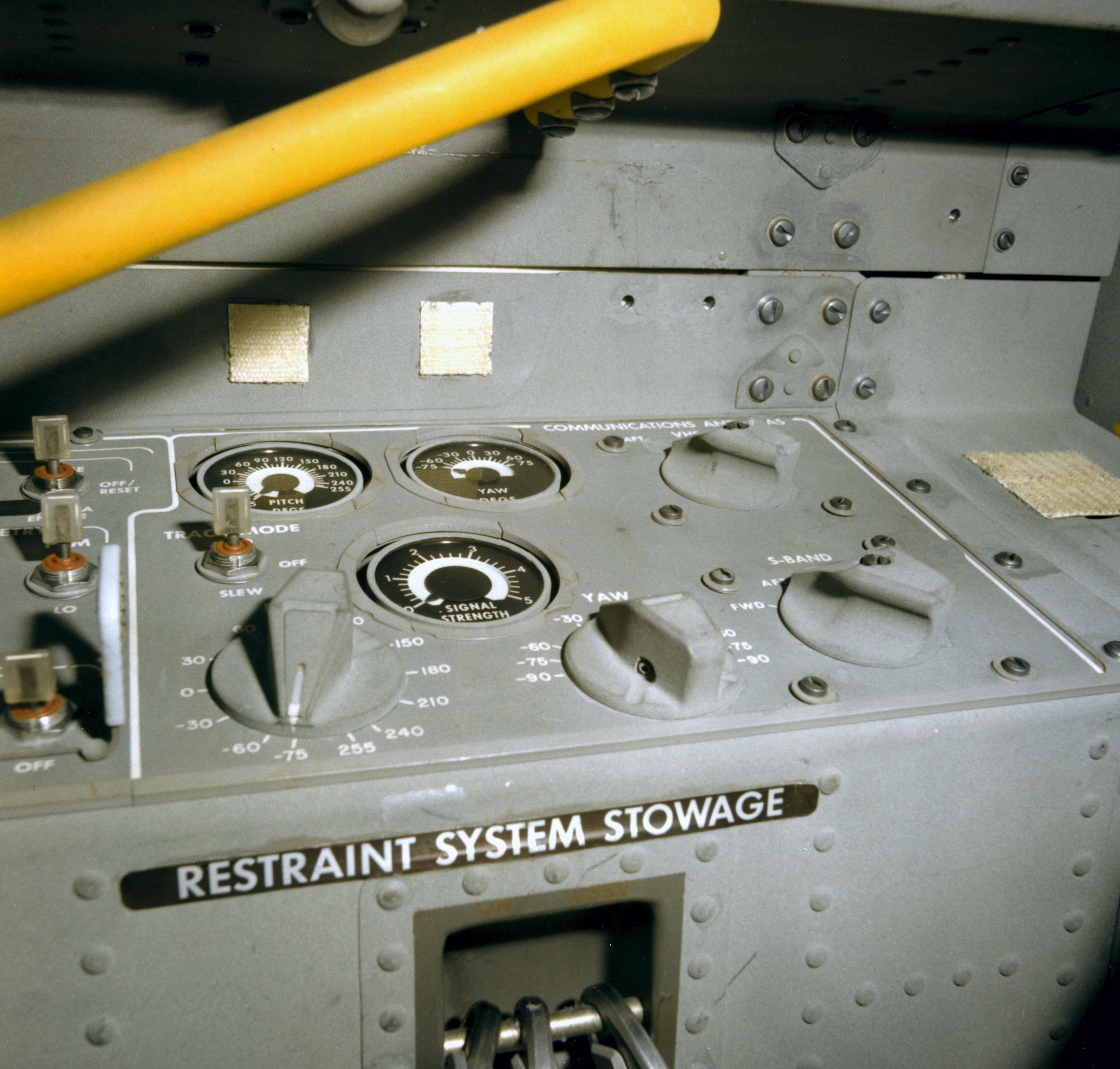
(6) Panel 14, forward section, Electrical Power, Descent Power; Panel 12, forward section (partial), Audio, Communications (1.9 Mb)
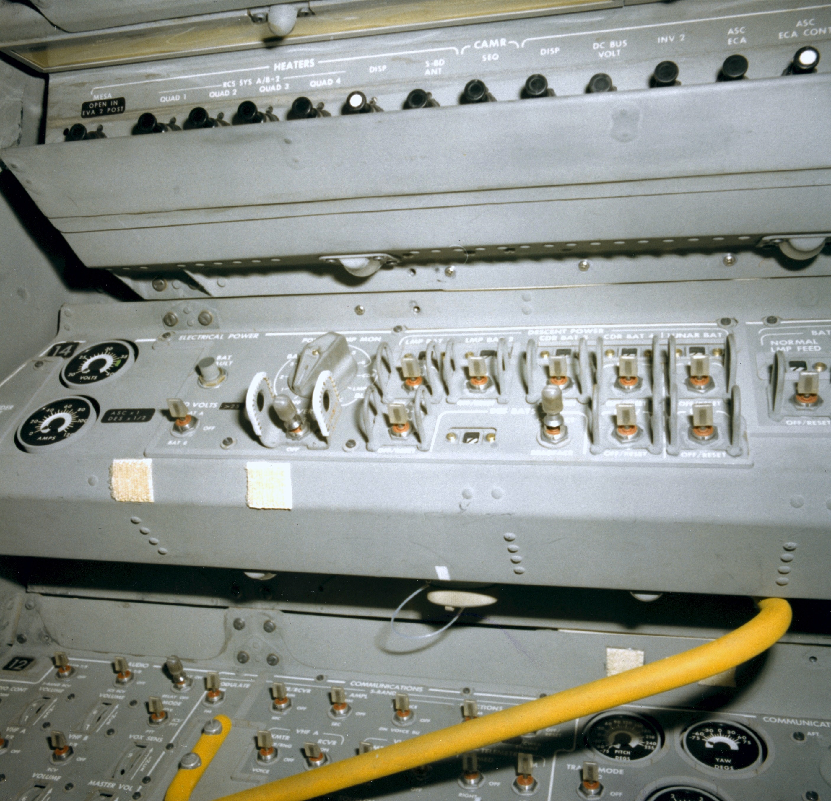
(7) Panel 14 aft section, Descent Power, Ascent Power, Comm (2.0 Mb)
(8) LMP's Thrust/Translation Controller Assembly (TTCA) (1.7 Mb)
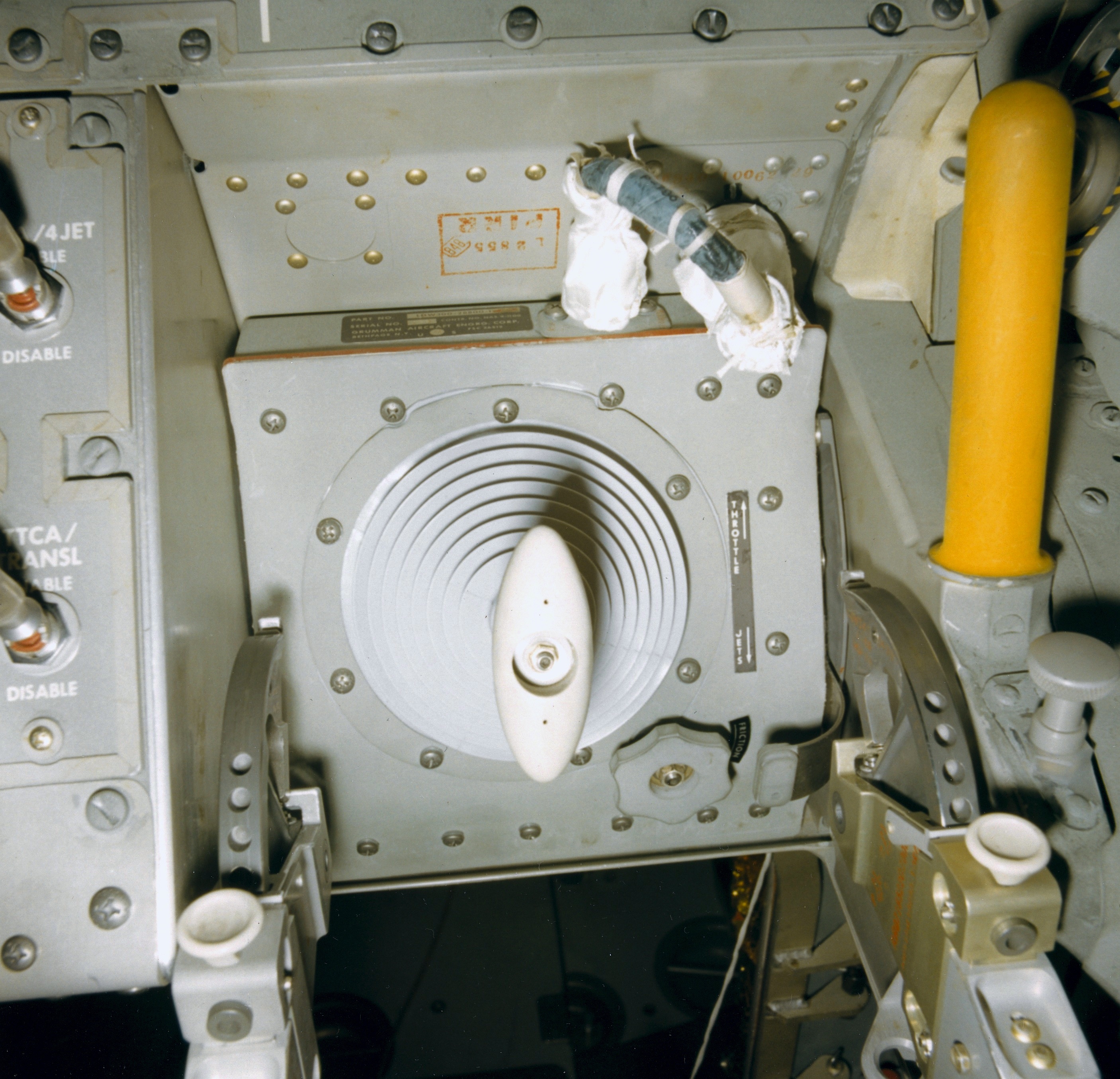
Overhead
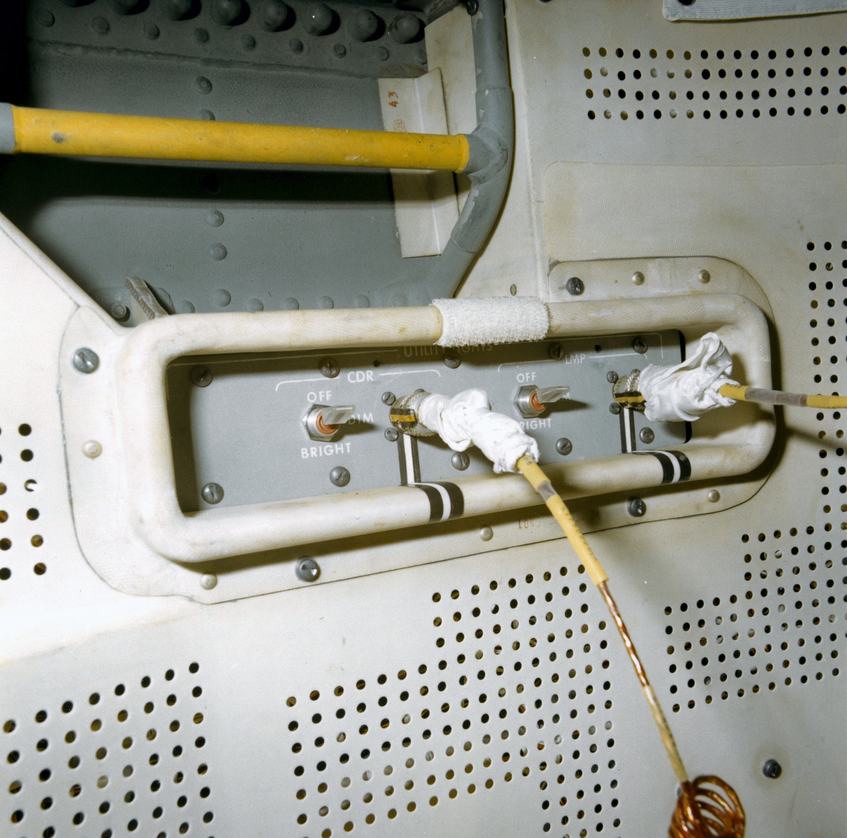
(1) Utility Light Plug receptacles and switches. Yellow handgrip in a recess. The LEC pulley was hooked onto the handgrip during LEC operations. (2.0 Mb)
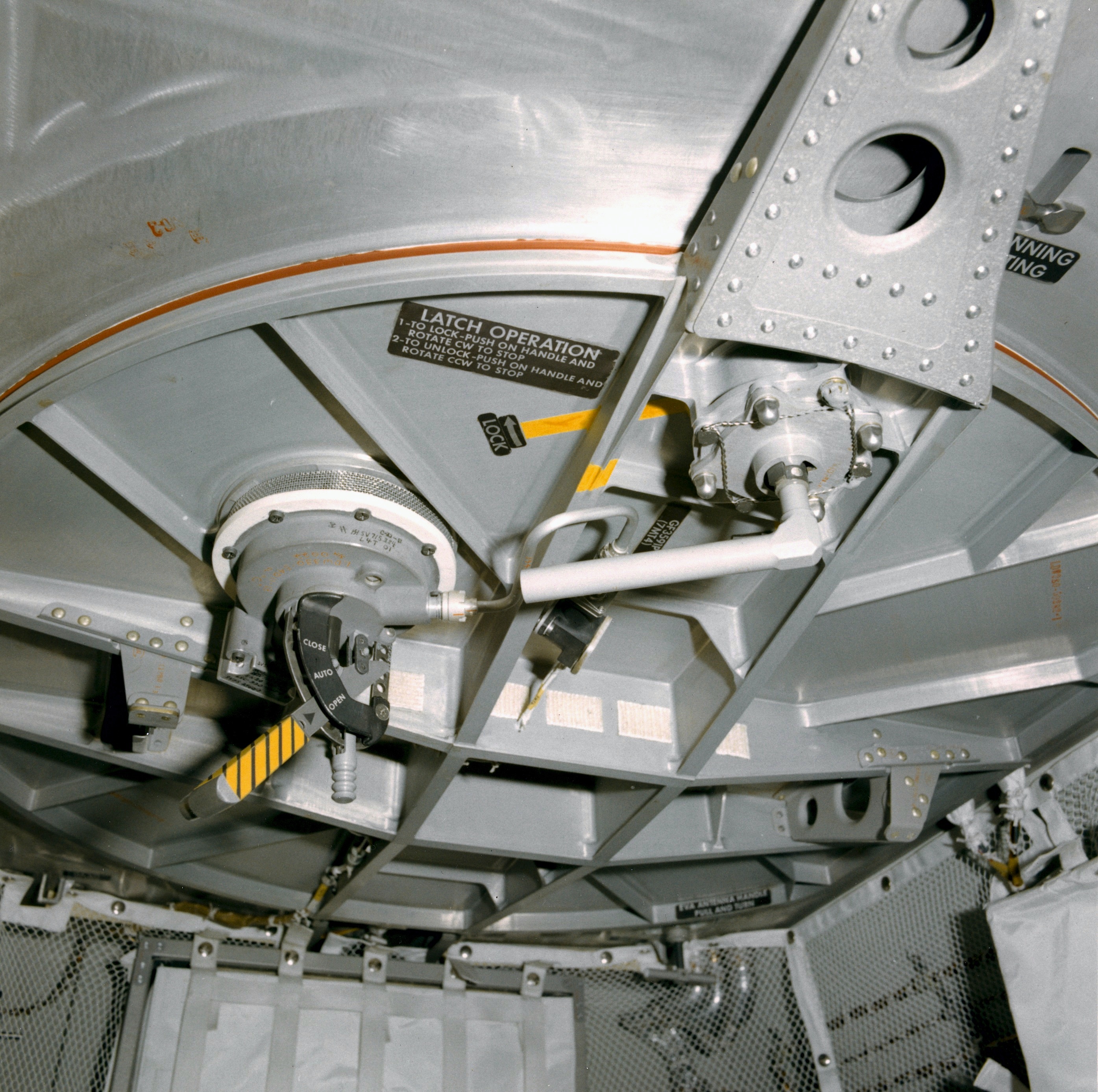
(2) Closed Docking Hatch (2.1 Mb)
Stowage
(1) Interim Stowage Assembly (ISA) after installation, hanging from the ceiling immediately aft of the AOT. Later, during LM checkout on the way out to the Moon, the ISA was moved to the bulkhead behind the CDR's station. The utilty lights are stowed in the ISA. Their yellow/gold coil cables are plugged into receptacles in the ceiling. (1.8 Mb)
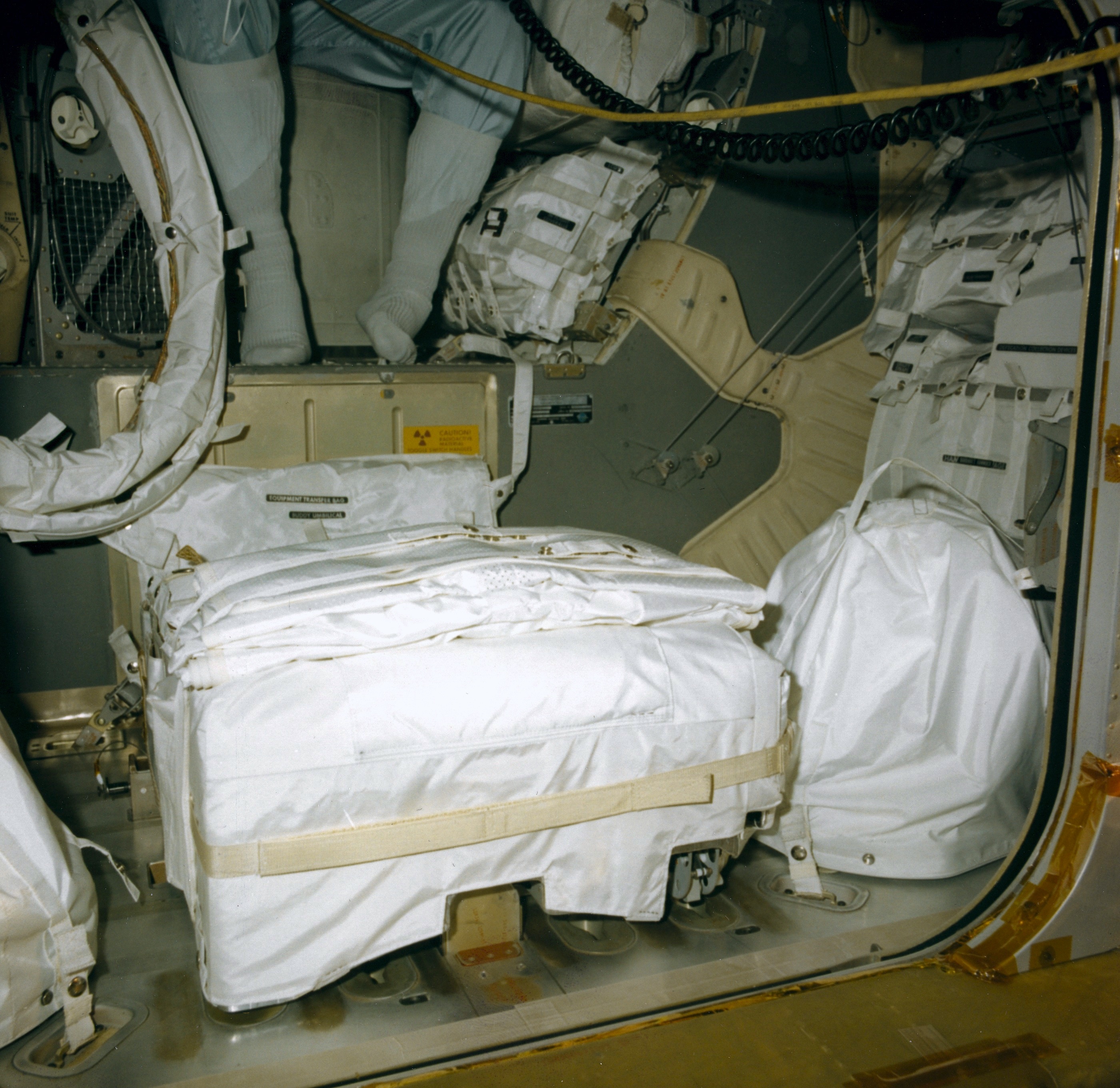
(2) View through the open hatch of LMP PLSS, both helmet bags, the ETB beyond the PLSS, and the LHSSC. A member of the close-out team is sitting on the ascent engine cover with his feet on the midstep. His left knee is against the bottom of the CDR PLSS. Stowed beneath the CDR PLSS are the Liquid Cooled Garments (LCGs) and In-Flight Coveralls. (1.8 Mb)
(3) Similar view through the open hatch but aimed more to the left. Shows the RHSSC and the forward face of the ECS equipment up on the midstep (1.8 Mb)
(1) Utility Light Plug receptacles and switches. Yellow handgrip in a recess. The LEC pulley was hooked onto the handgrip during LEC operations. (2.0 Mb)
(2) Closed Docking Hatch (2.1 Mb)
Stowage
(1) Interim Stowage Assembly (ISA) after installation, hanging from the ceiling immediately aft of the AOT. Later, during LM checkout on the way out to the Moon, the ISA was moved to the bulkhead behind the CDR's station. The utilty lights are stowed in the ISA. Their yellow/gold coil cables are plugged into receptacles in the ceiling. (1.8 Mb)
(2) View through the open hatch of LMP PLSS, both helmet bags, the ETB beyond the PLSS, and the LHSSC. A member of the close-out team is sitting on the ascent engine cover with his feet on the midstep. His left knee is against the bottom of the CDR PLSS. Stowed beneath the CDR PLSS are the Liquid Cooled Garments (LCGs) and In-Flight Coveralls. (1.8 Mb)
(3) Similar view through the open hatch but aimed more to the left. Shows the RHSSC and the forward face of the ECS equipment up on the midstep (1.8 Mb)
| Journal Home Page | Apollo 17 Journal |