
| Journal Home Page | Apollo 11 Journal |
Lunar Surface Flown Apollo 11 Artifacts
From the Neil Armstrong Estate
National Air and Space Museum, Washington D.C.
Assembled by Eric Jones, Ulli Lotzmann, Ken Glover, and Allan
Needell.
Except where noted, photos were taken by Lisa Young of the
National Air and Space Museum Conservation Unit
in November-December 2014. Additional images were taken on
April 14, 2014 by Ulli Lotzmann at the
Paul E. Garber Facility, Suitland, Maryland, with special thanks
to Allan Needell and Jennifer Levasseur.
Thanks, also, to Mike Blaney, Paul Fjeld, Brian McInall, Gary
Neff, J.L. Pickering, and Thomas Schwagmeier.
Last revised 6 January 2016.
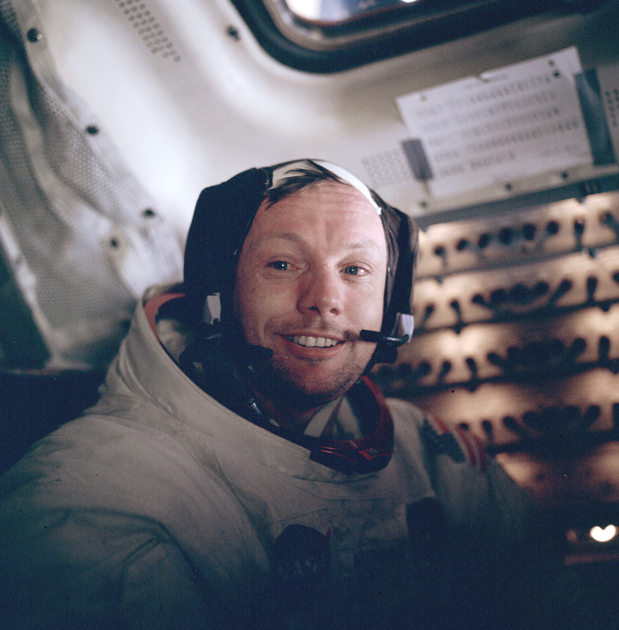
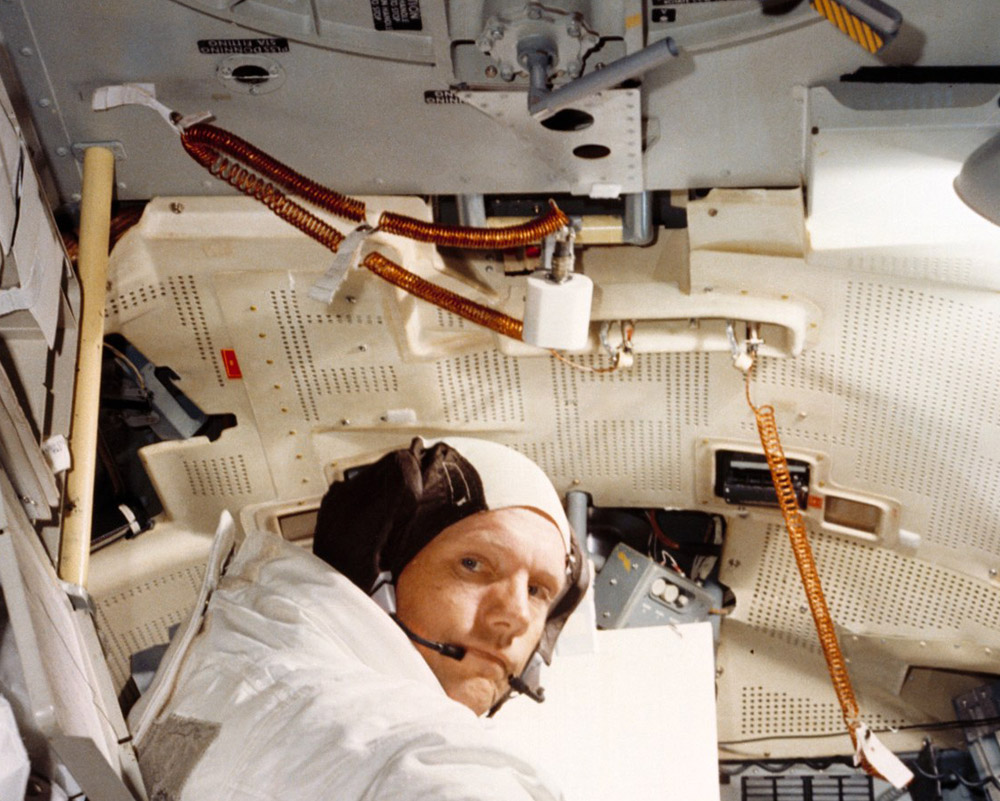
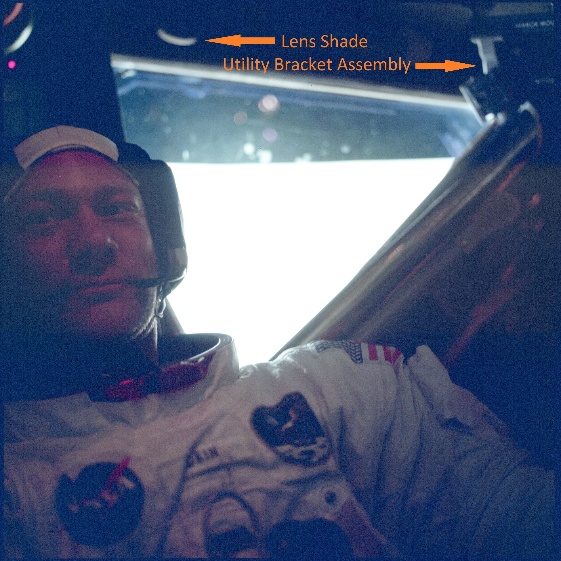
| A smiling Neil Armstrong
in the LM cabin after the EVA. (Click on the image for a larger version.) |
Apollo 11 Purse and Contents
After Neil Armstrong's death (25 August 2012),
his widow, Carol, discovered a white, (beta)cloth bag in a
closet, containing what were obviously either flight or space
related artifacts. She contacted Allan Needell, curator of the
Apollo collection at the Smithsonian's National Air and Space
Museum, and provided photographs of the items. Needell,
who immediately realized that the bag - known to the astronauts
as the Purse - and its contents could be hardware from the
Apollo 11 mission, asked the authors for support in identifying
and documenting the flight history and purpose of these
artifacts. After some research it became apparent that the purse
and its contents were lunar surface equipment carried in the
Lunar Module Eagle during the epic journey of Apollo 11. These
artifacts are among the very few Apollo 11 flown items brought
back from Tranquility Base and, thus, are of priceless
historical value. Of utmost importance is the 16mm movie camera
with its 10mm lens. The camera was mounted behind the
right forward window of the lunar module and was used to
film the final phase of the descent to the lunar surface, the
landing, as well as Neil Armstrong‘s and Buzz Aldrin‘s
activities on the lunar surface including taking the first
samples of lunar soil and planting the US flag. Thanks to
the Neil Armstrong family, the Apollo 11 purse and its contents
are now on loan at the National Air and Space Museum for
preservation, research and eventual public display.
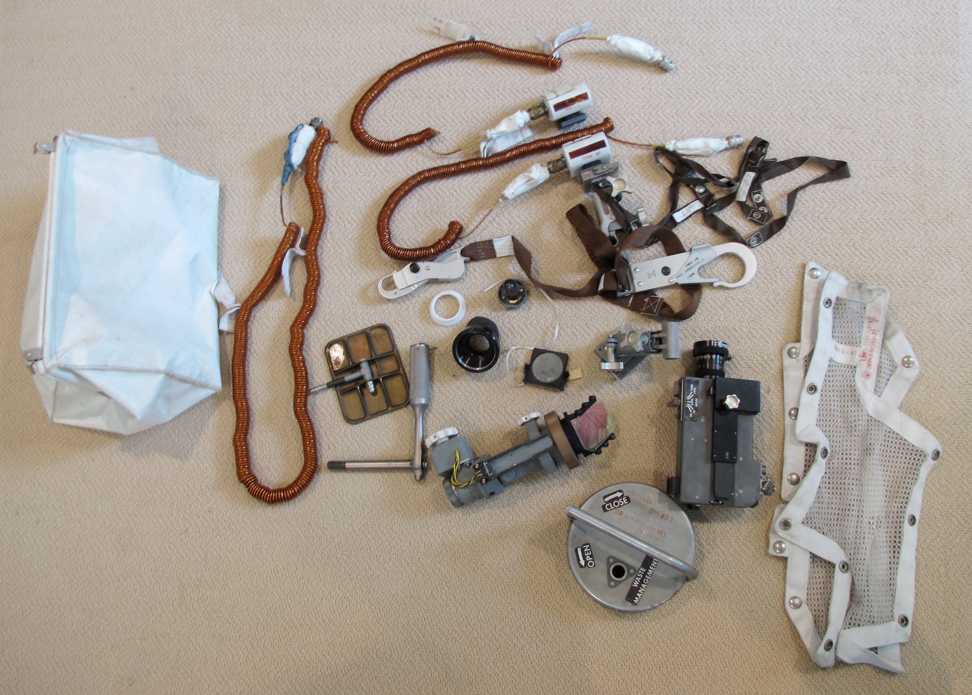
| The photo above was
provided to Allan Needell by Carol Armstrong and shows
the bag and its contents after their discovery. Used
with permission. (Click on the image for a larger
version.) |
Clickable Collection Map

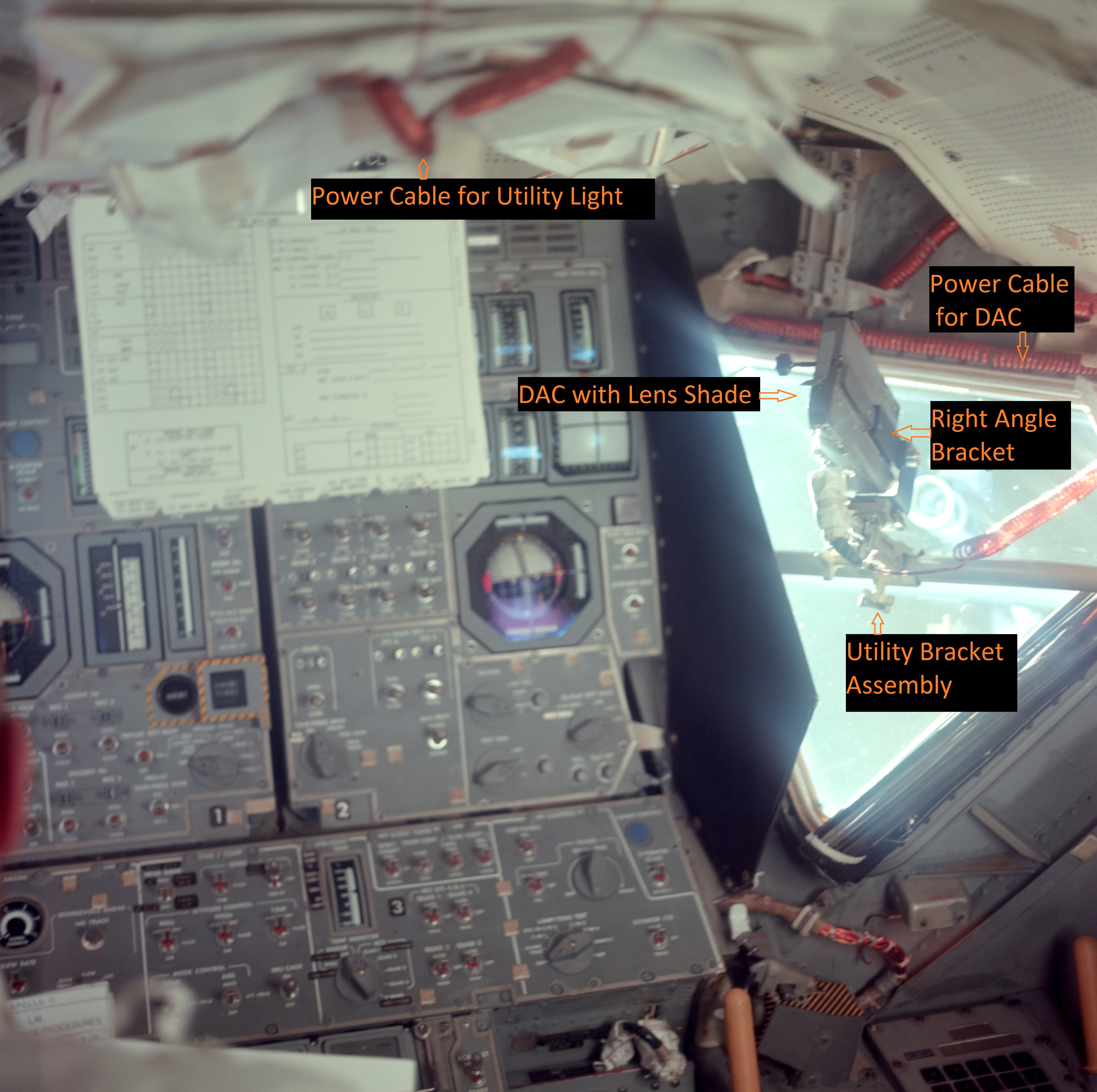
| In this version of the
photograph, 20 individual items are numbered. The
numbers can be clicked on the image or in the table for
access to further information about each item. The
right-angle bracket (numbered 12a in the table) and the
10-mm lens (12b) are attached to the DAC. |
Table: Part and Serial Numbers
(Click on the item number to go to a discussion of the item)| Item Number |
Name |
Part Number |
Serial Number |
| 1 | Temporary Stowage Bag (aka 'Purse') |
LDW340-53444-1 |
0014 |
| 2 |
Power Cable for DAC (item 12) |
LDW340-52689 |
0004 |
| 3 |
Utility Light with Power Cable |
LDW340-53053-3-3 |
0002 |
| 4 |
Utility Light |
LDW340-53053-3-3 | 0001 |
| 5 |
Utility Bracket Assembly (aka Utility
Clamp) |
LDW-340M11566-11;
LDW340-52040-1-1; LD-340-53051-3 |
Inspection stamp 651 |
| 6 |
Utility Bracket Assembly (aka Utility Clamp) | LDW-340M11566-11; LDW340-52040-1-1; LD-340-53051-3 | Inspection stamp 738 |
| 7 |
Crewman Optical Alignment Sight (COAS) |
ME331-0018-0021 |
06359-0741 BKA |
| 8 |
Filter (Snap-on for COAS) |
ME331-0018-0023 | 06359-1285BKA |
| 9 |
Light Bulb Assembly (Spare for COAS) |
B50258-1 |
152 |
| 10 |
Waist Tether (aka EVA Tether) |
SEB33100192-305; SEB33100221-303 (large
snaphook); SEB331100200-303 (small snaphook) |
1033; 2001; 2005 |
| 11 |
Helmet Tie Down Strap (2) |
SEB33100016-302 | 1101; 1102 |
| 12 |
Data Acquisition Camera (DAC -16mm movie) | SEB33100100-206 |
1035 |
| 12a |
Right-Angle Bracket Adapter (for DAC) |
SEB331 00277-303 |
1008 |
| 12b |
10-mm lens (for DAC) |
SEB331-00010-302 |
1016 |
| 13 |
Lens Shade (Teflon; for 10mm lens on DAC) |
N/A |
N/A |
| 14 |
Eyeguard Assembly (for AOT) |
6011834-011; 6011104A |
KIC 22; KIC 29 |
| 15 |
Mirror (Metal) |
LDW340-52035-3-2 |
NA |
| 16 |
Tool B - Emergency Wrench |
V36-601400-21 |
0632 AAH 6103 |
| 17 |
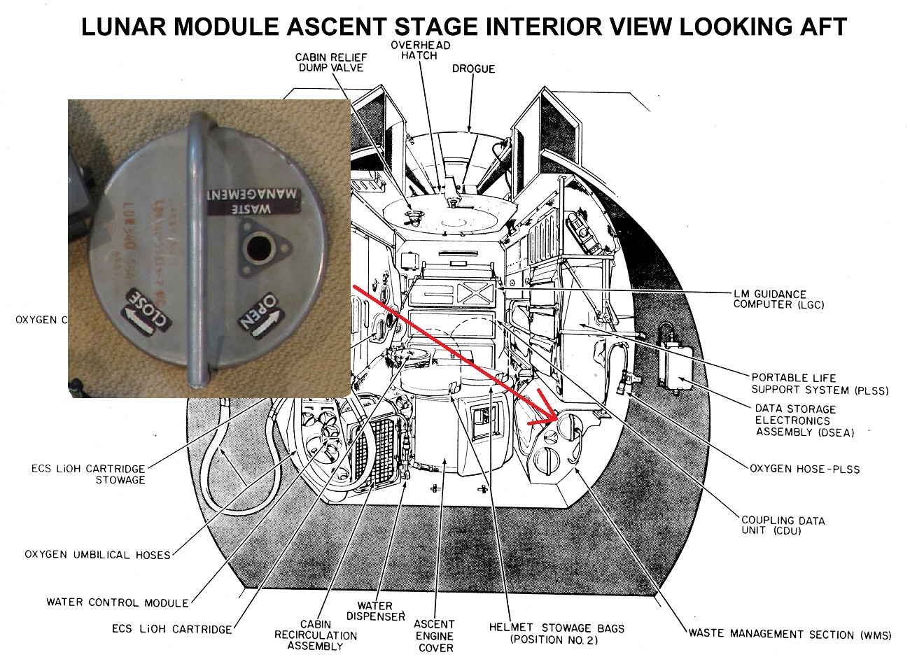
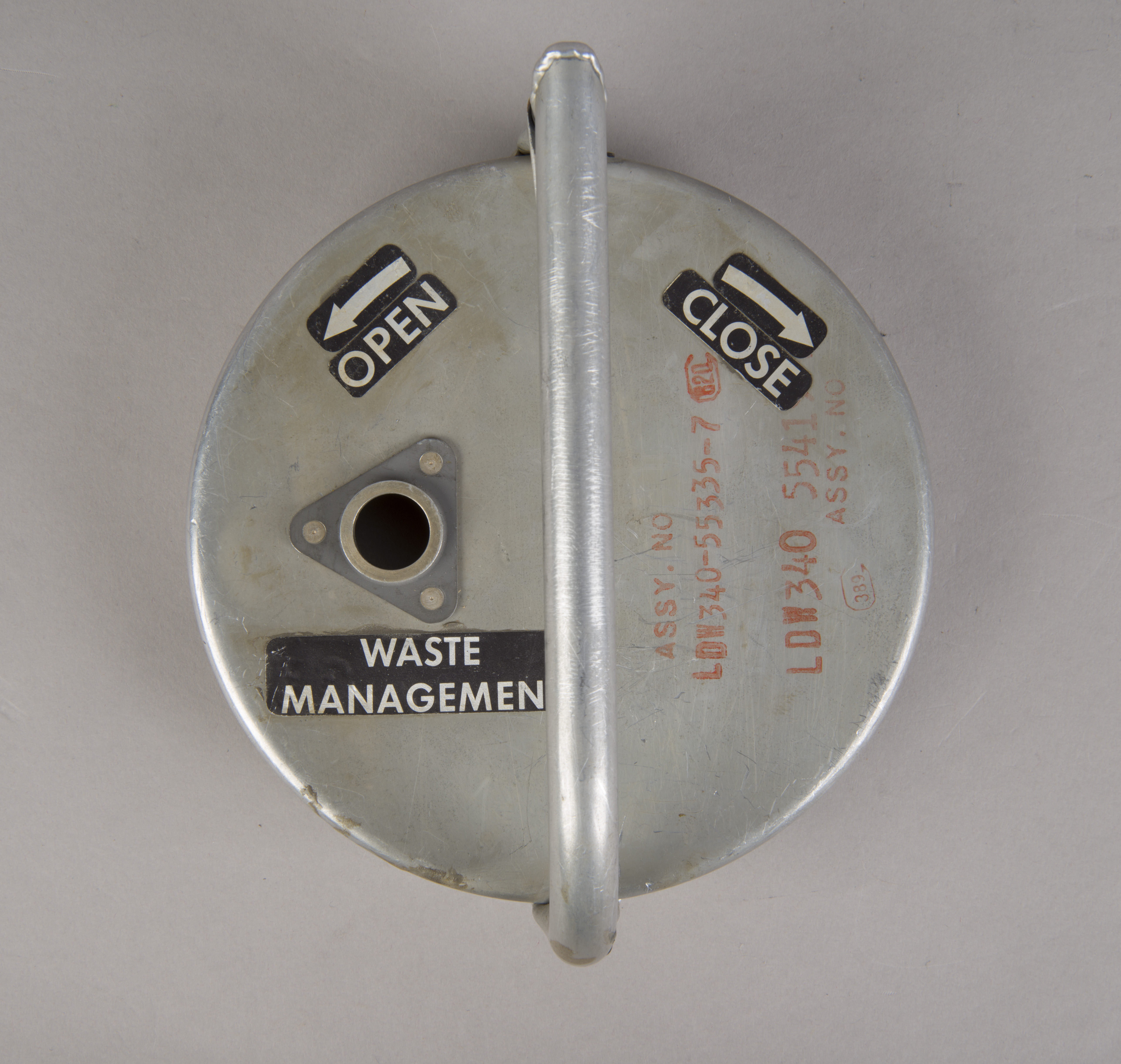
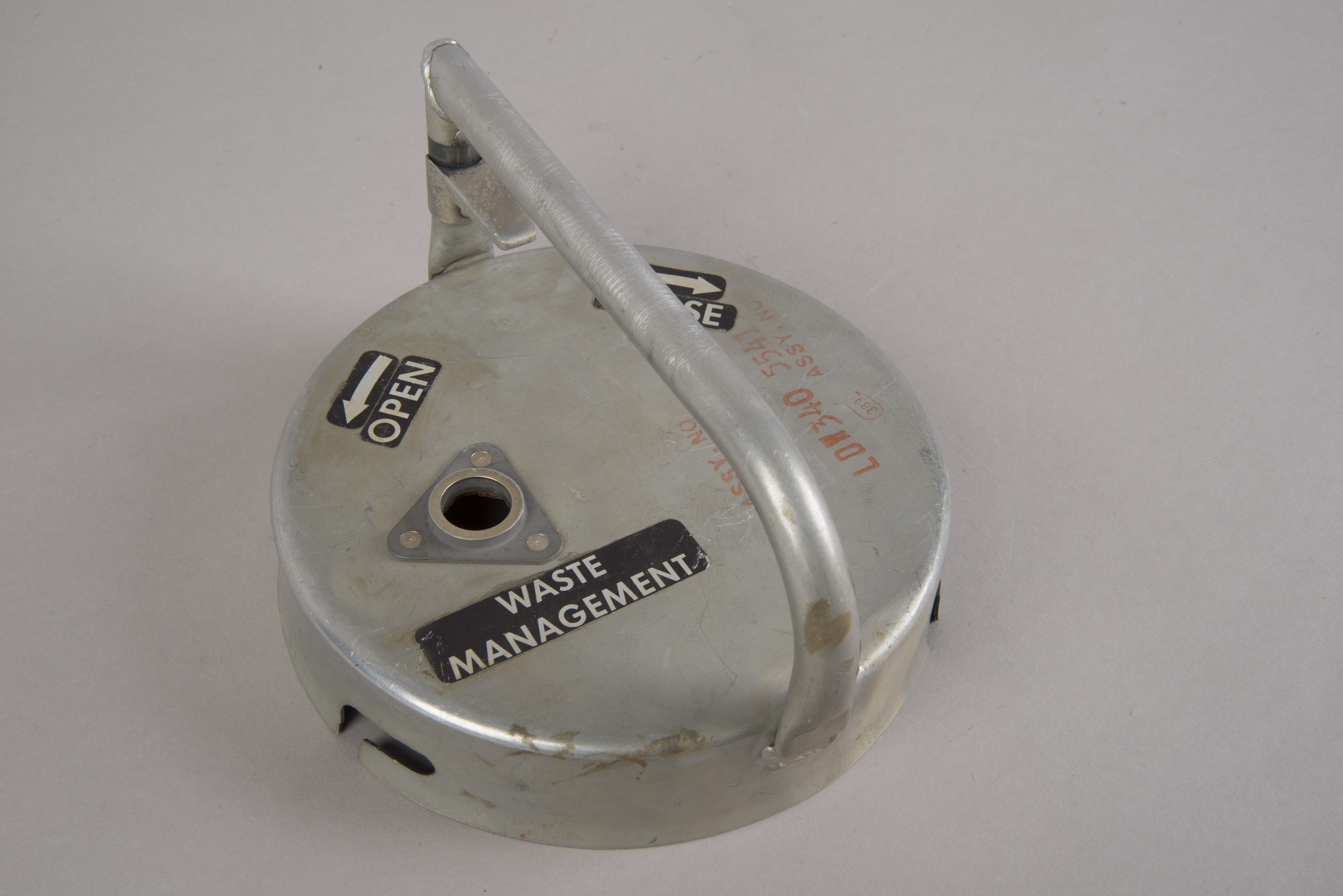
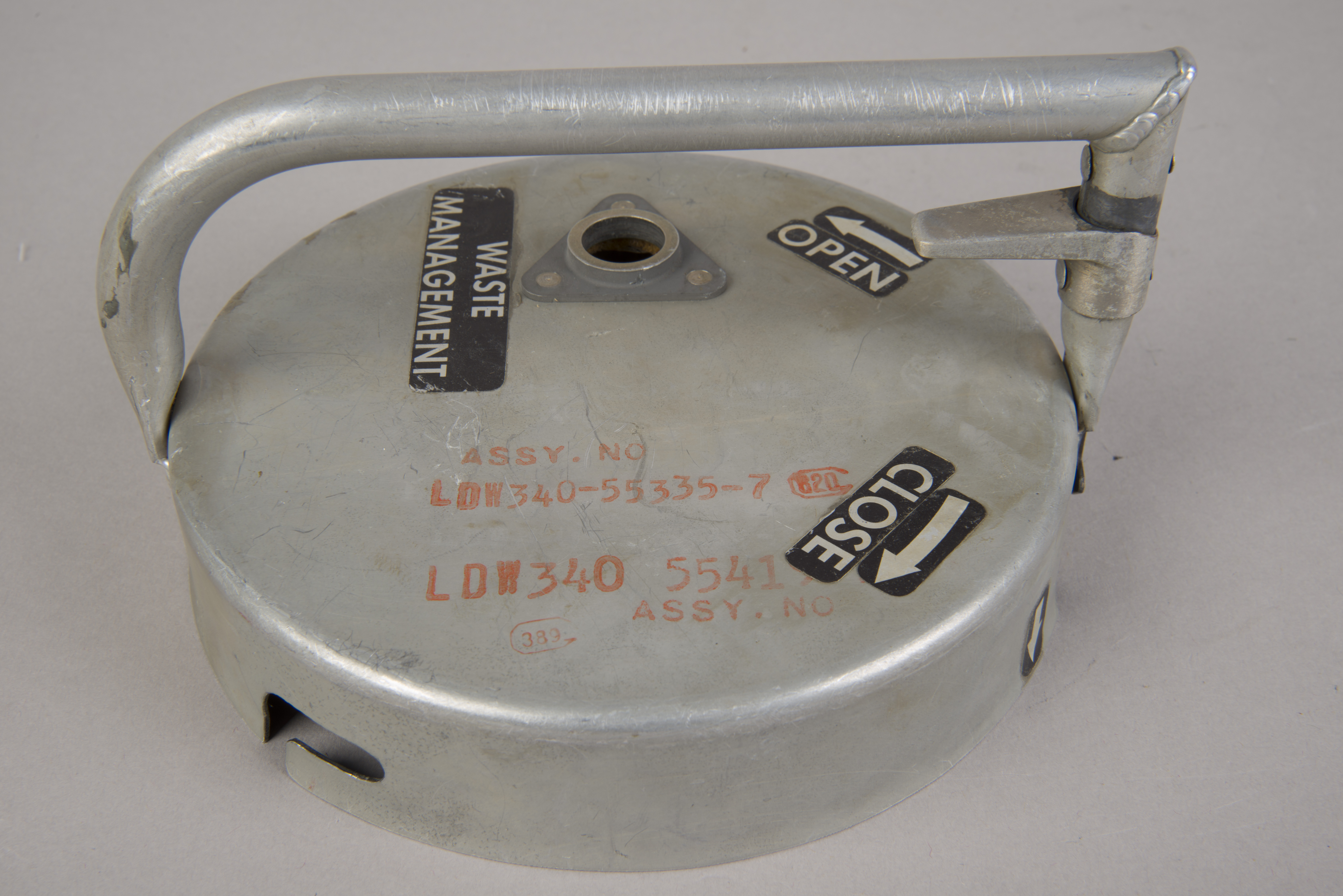
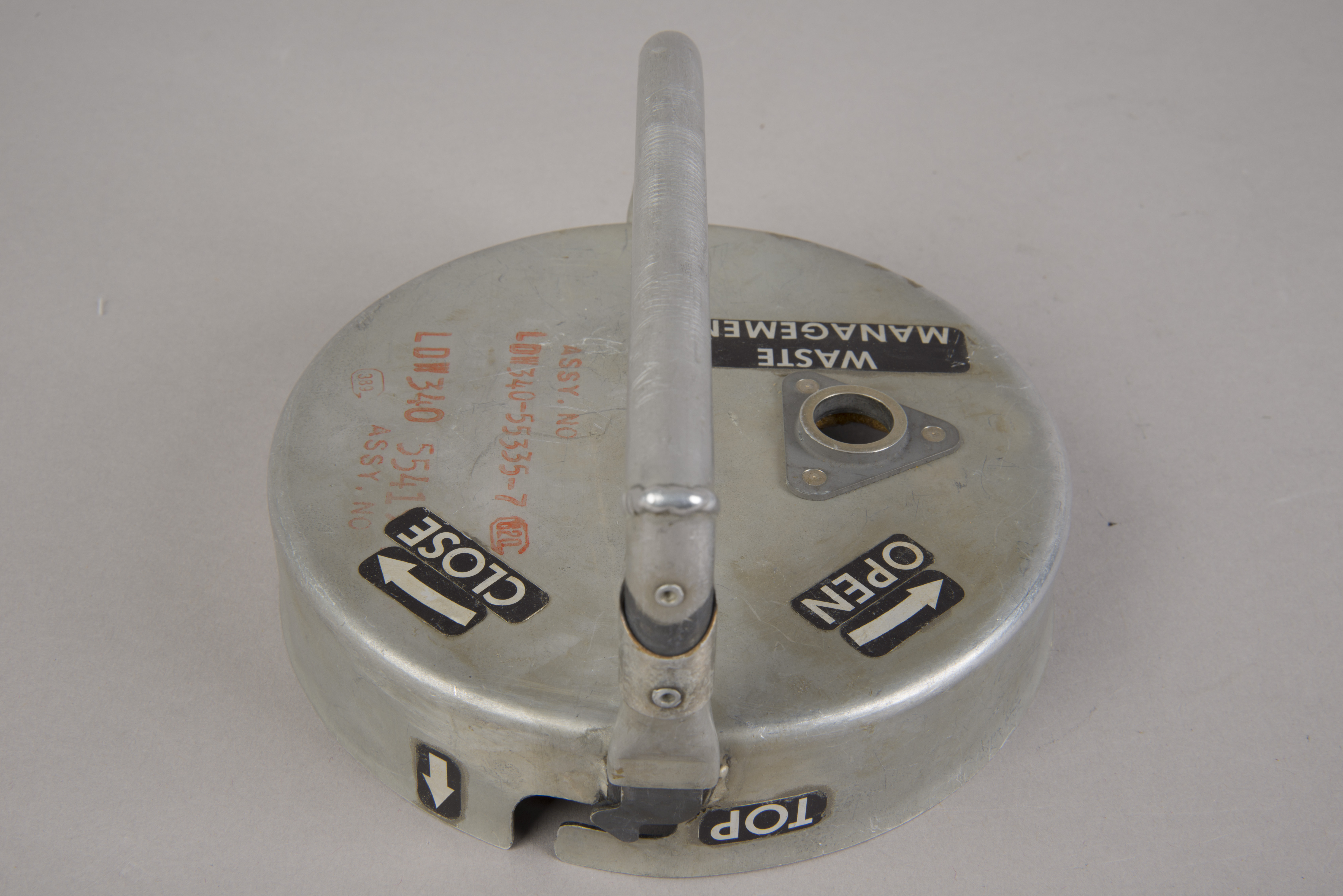
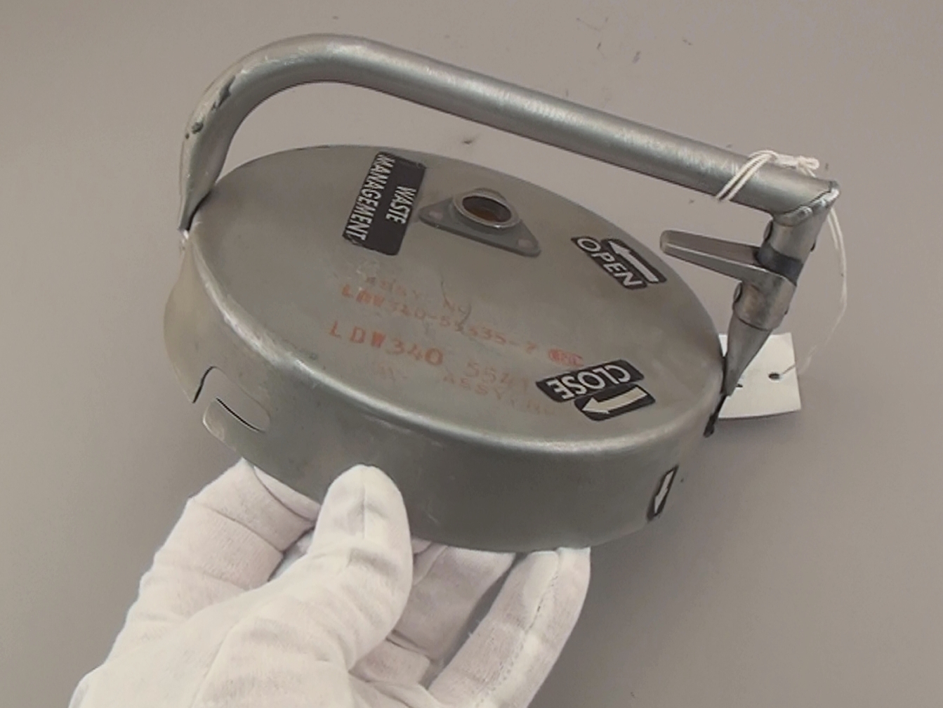
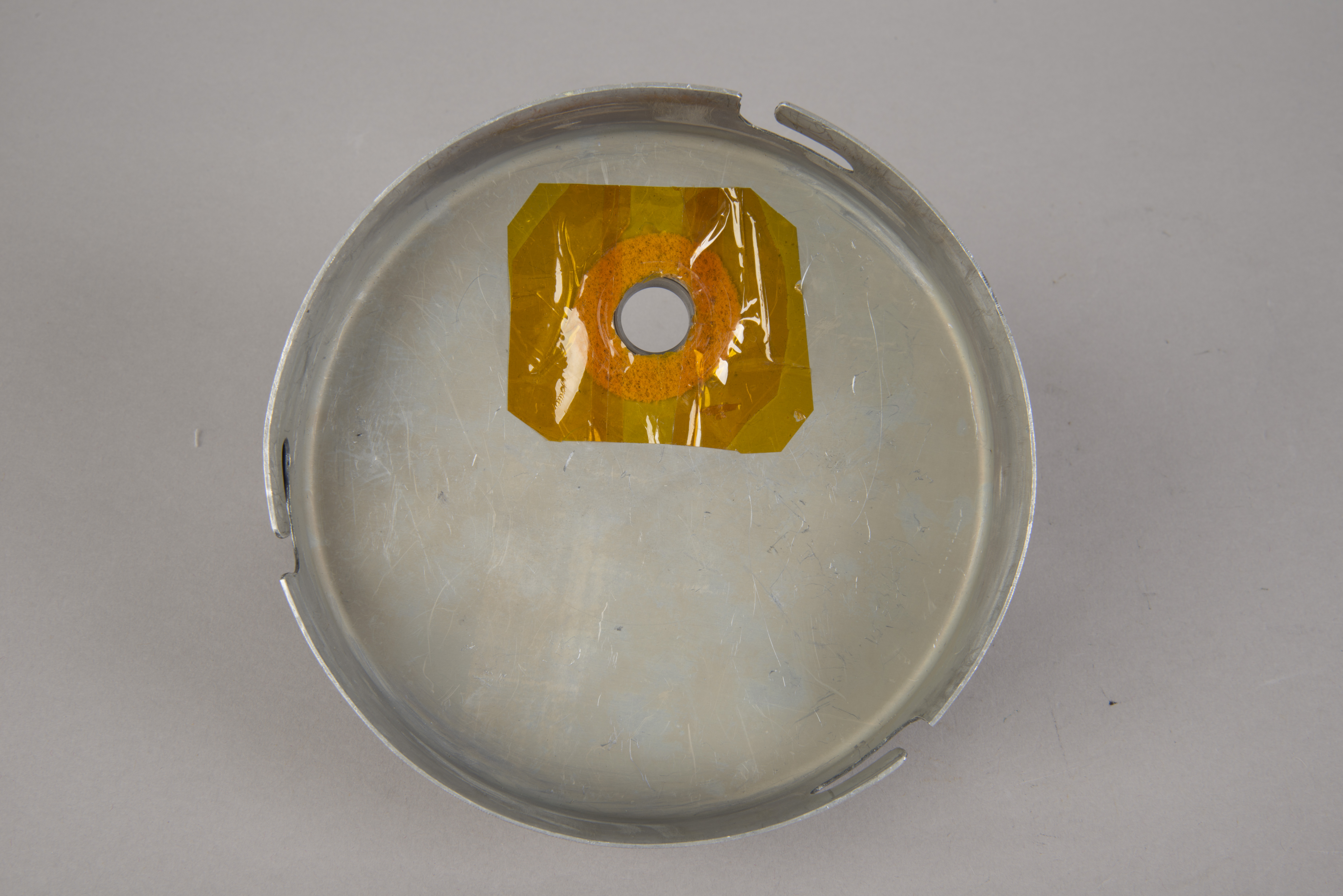
Waste Management Cover |
LDW340-55335-7 |
|
| 18 |
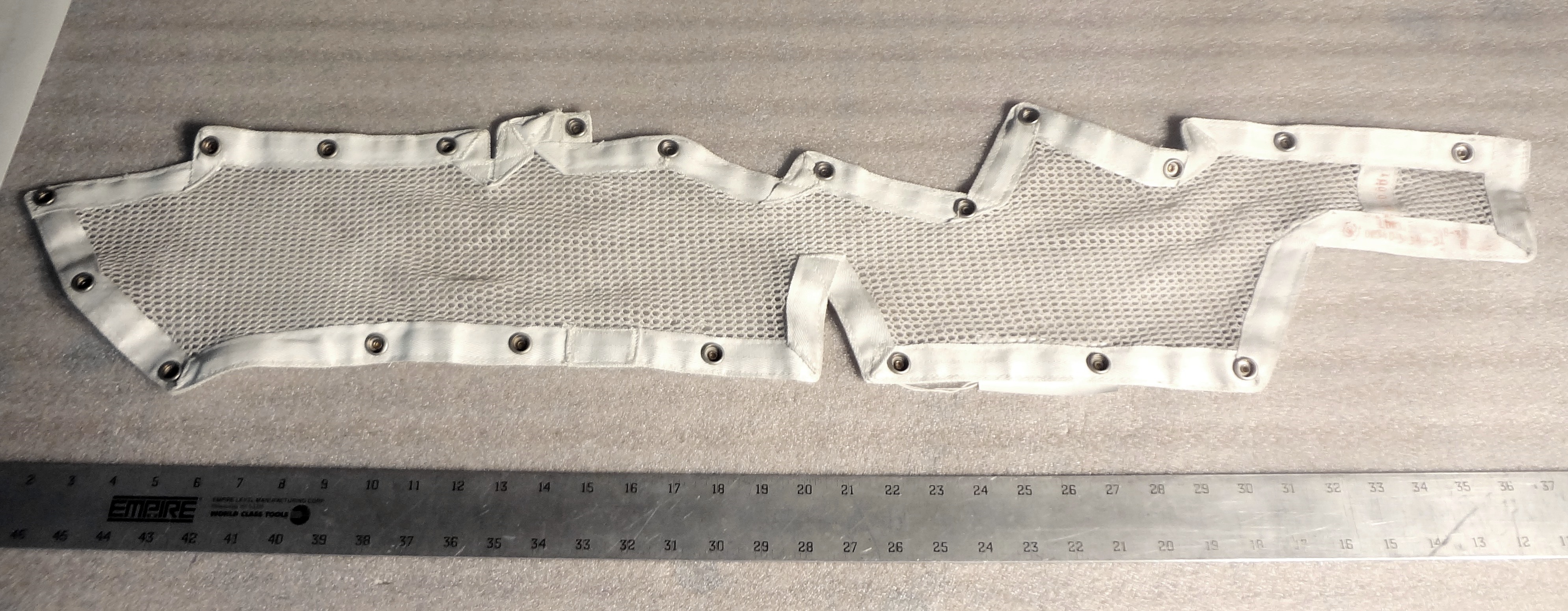
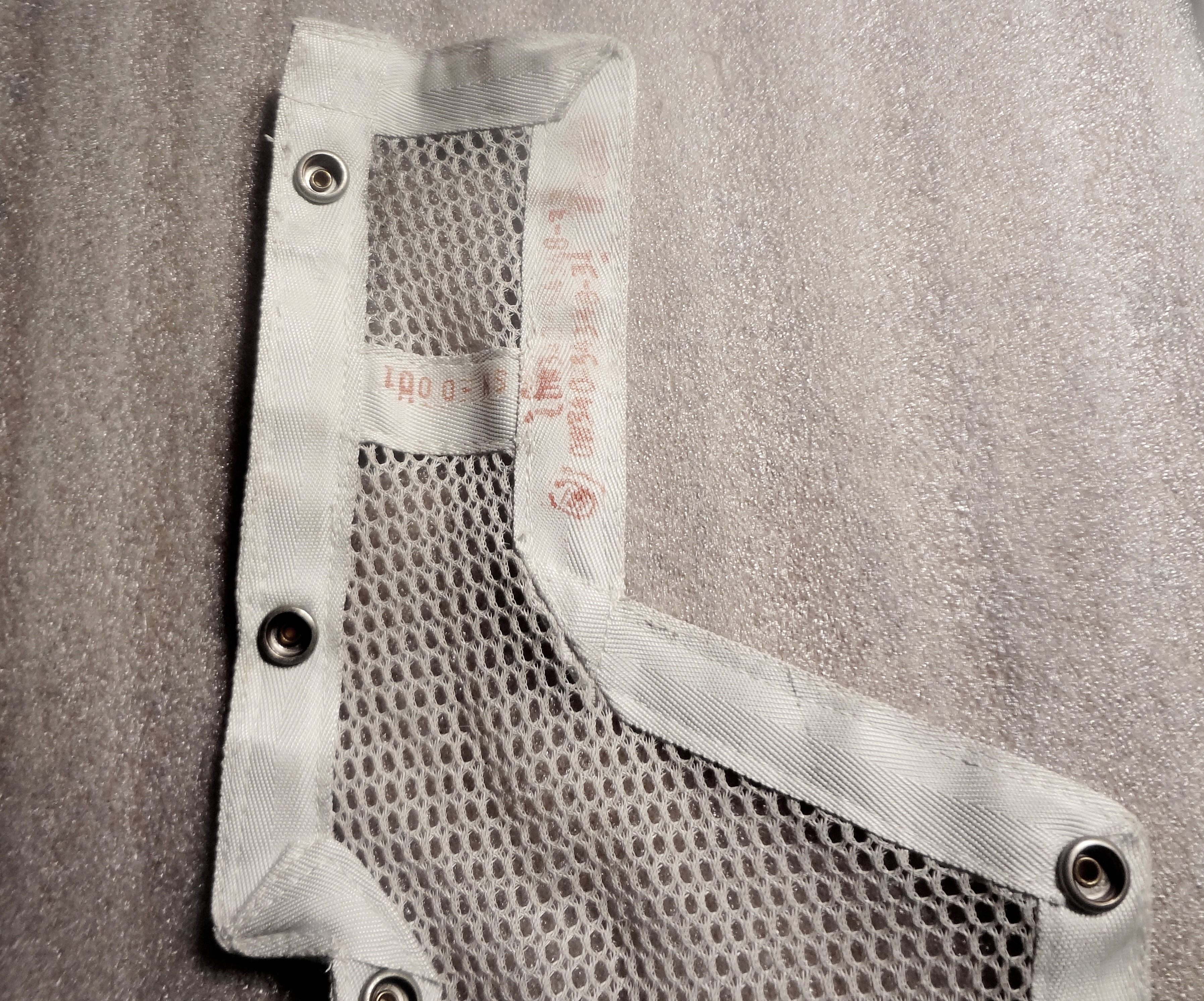
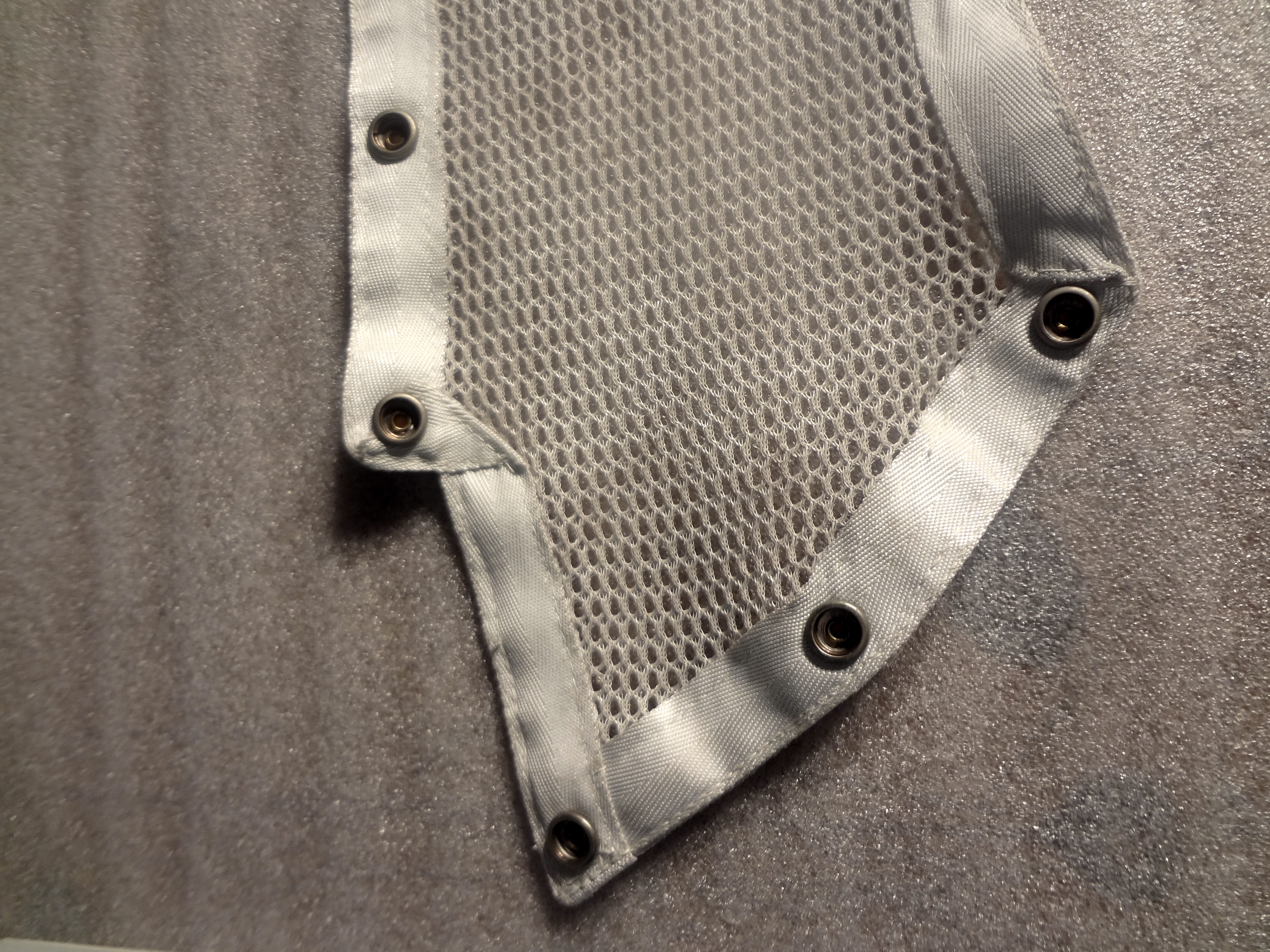
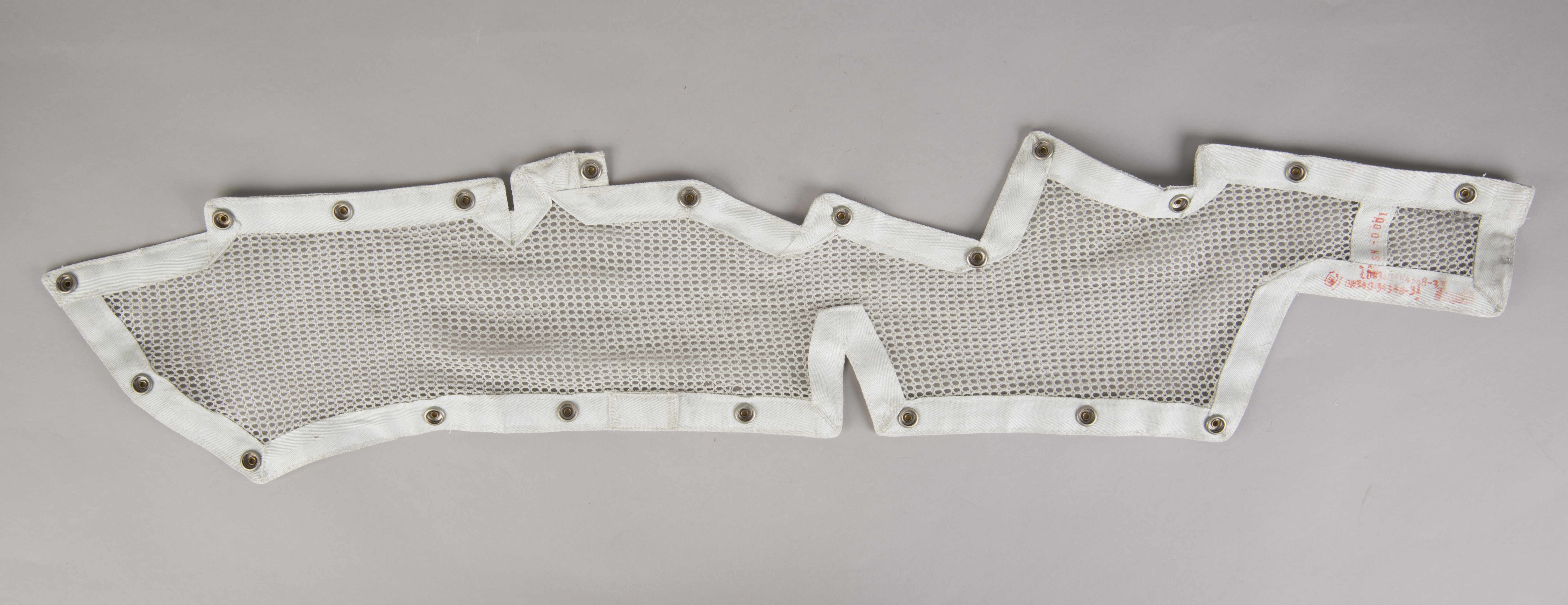
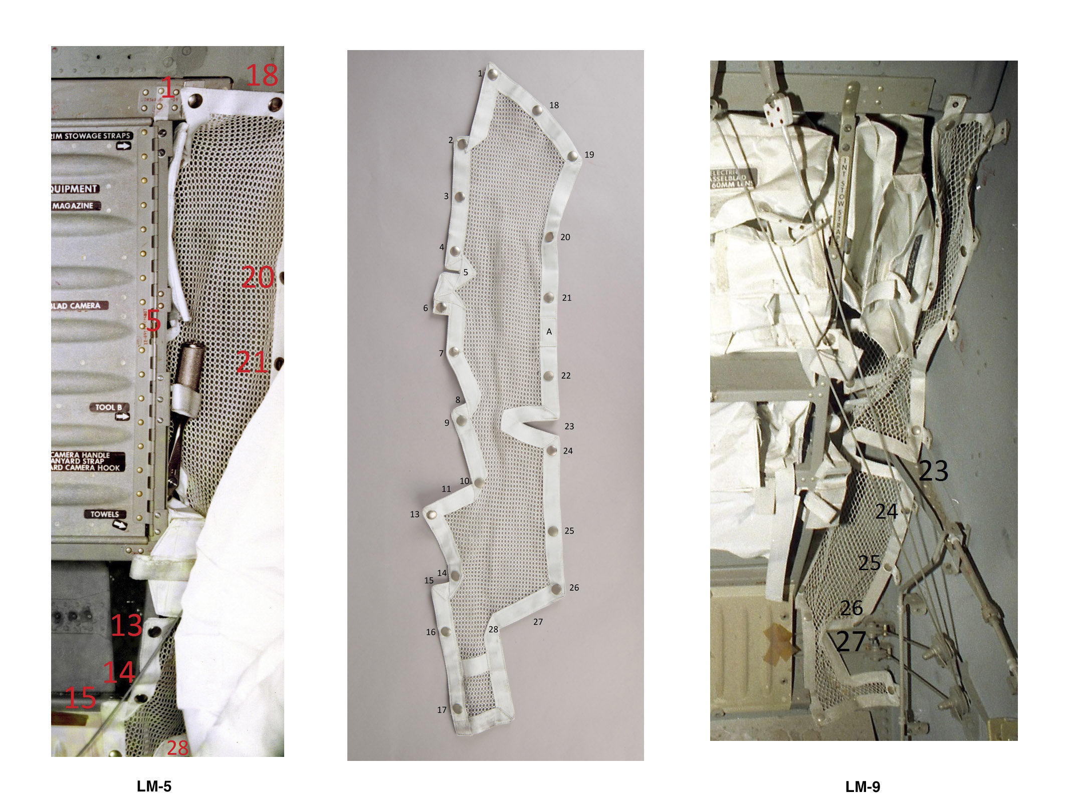
Netting |
LDW340-54348-31 |
0001 |
| The purse and its contents were mentioned
by the crew on three occasions after Neil and Buzz
rejoined Mike Collins in lunar orbit. (1) After Neil and Buzz pass the rock boxes and the contingency sample across to Mike, about an hour after they get the hatches of the two docked spacecraft open and about 50 minutes before they jettison the LM, Neil says to Mike, almost certainly while passing the purse across: 129:14:53 CDR: You know, that - that one's just a bunch of trash that we want to take back - LM parts, odds and ends, and it won't stay closed by itself. We'll have to figure something out for it.(2) Nearly 24 hours after the Trans-Earth Injection burn, Mike tells CapCom Charlie Duke: 156:17:10 CMP: What we'll do Charlie, tomorrow, is go through and reconfigure our stowage as closely as possible to nominal. Some things that will not be nominal are as follows: the EVA visors were brought back into the Command Module, and we have not yet found a home for them. We'll let you know where they go. In addition, there's about 5 pounds of miscellaneous weight from the LM in compartment A-8, and it's taking the place of the LCGs which we moved from A-8 into the suit bag. We got rid of one miscellaneous trash bag, mostly old food wrapping and also old underwear and that helmet protective visor of the CMP's. We left all that with Eagle. And those are about the only off-nominals we have. (3) About a half hour before the crew's final rest period before re-entry and splashdown, Mike is reviewing the Entry Checklist with Charlie Duke: 181:38:04 CMP: And compartment A8, delete two LCG's, add one PPK (Personal Preference Kit), making a total of four, and add 10 pounds of LM miscellaneous equipment. We told you five the other day. We think ten is probably closer.These transmissions clearly indicate that the purse was stowed in CM compartment A-8 from at least 156:17:10 onward. As for the estimated weights Mike mentioned, the following are A11 stowage list weights for the large items that came back in the purse: DAC, 1.7 lb; COAS, 1.5; Mirror, 0.2; Utility Lights (2), 3.0 lb includes cords, clamps, and brackets. Total, these items, 6.4 lb. |
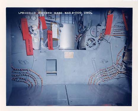
Temporary Stowage Bag (TSB or Purse)
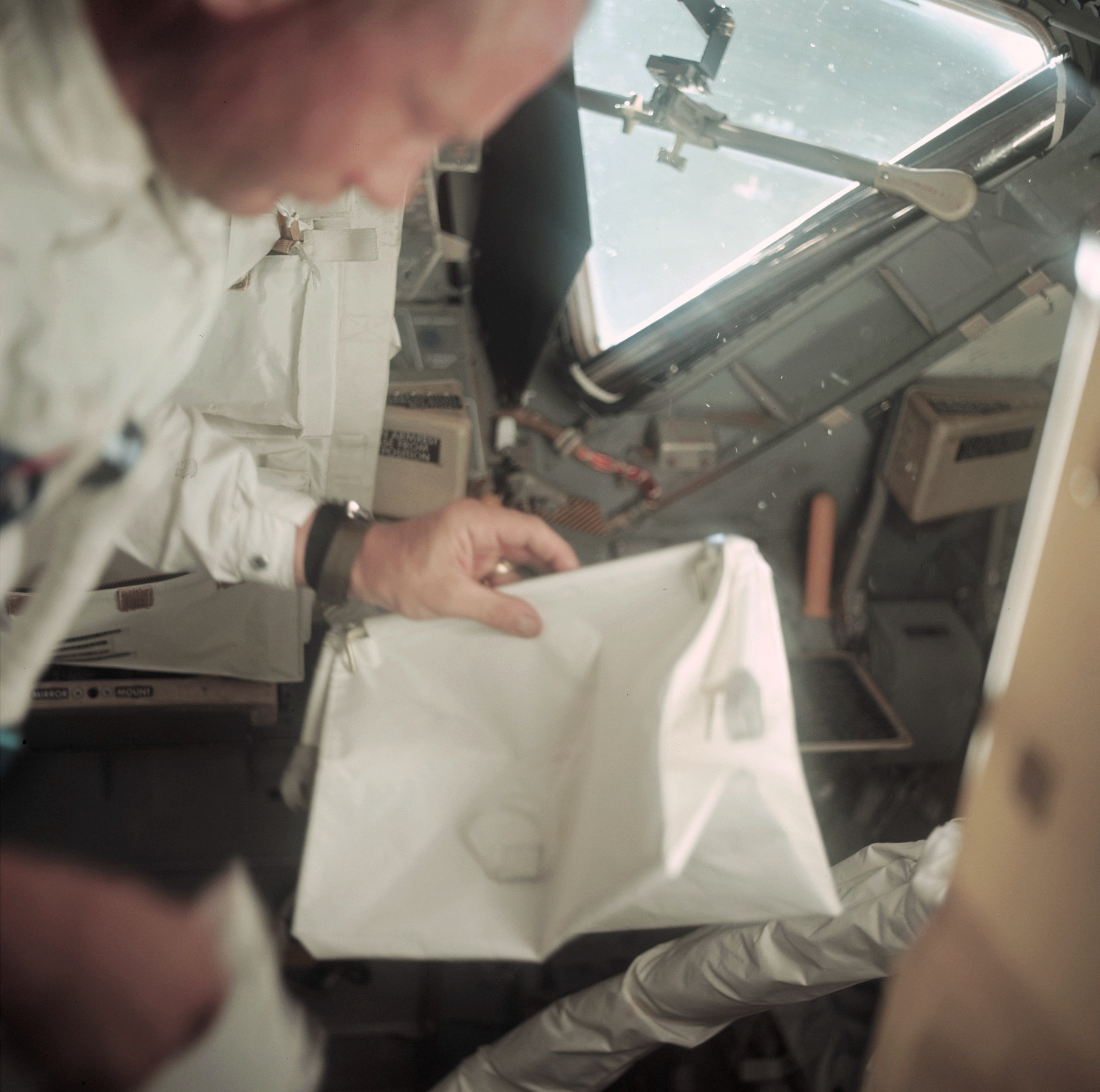
| Mission photograph AS-36-5397
shows Buzz Aldrin holding the TSB during a LM inspection
at about 55 hours 41 minutes into the mission on the way
out to the Moon. (Click on the image for a larger version.) |
The TSB was also called the McDivitt Purse - or just the Purse. During training for Apollo 9, Commander Jim McDivitt, recognized the need for a stowage bag that could be positioned at the front of the spacecraft to hold items, such as the purge valves, which might otherwise fall to the cabin floor while they were preparing for EVAs. The TSB resembles a woman's purse that opens at the top and, when closed, has a triangular cross section. Hence the name.
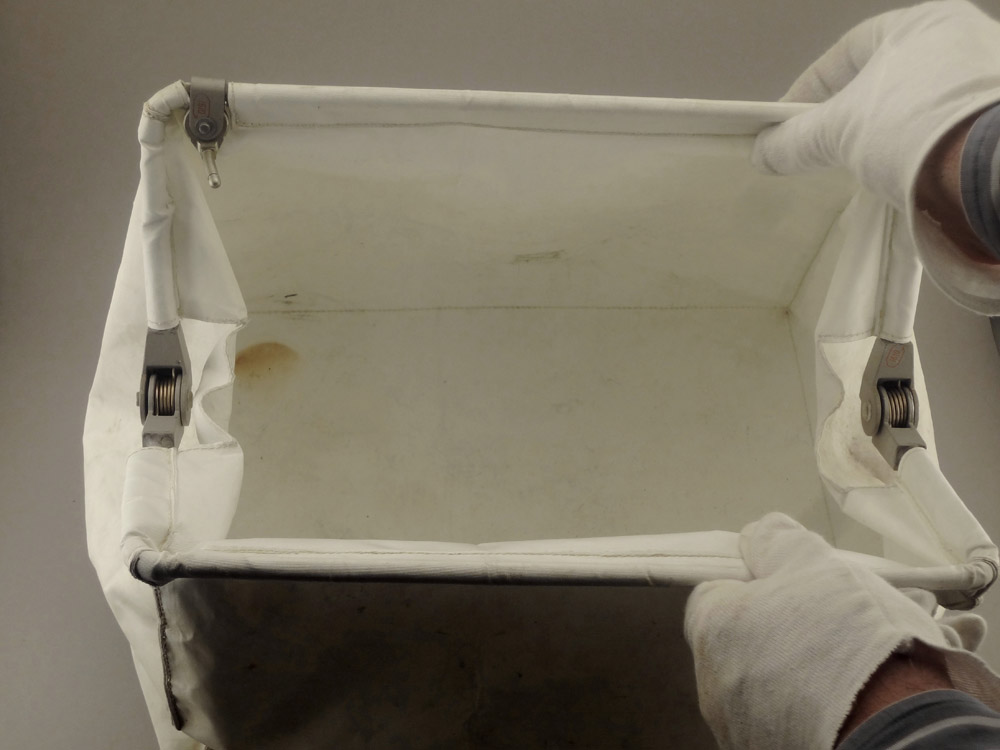
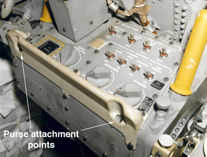
| Apollo 11 Purse with top
open. The pin at the upper left and a second pin at the
other end of the same bar were inserted in matching
holes on the edge of Panel 5, in front of the
Commander's station to the left of the hatch. The purse
attachment points in the Apollo 12 LM are shown in a labeled detail
from a photo
taken during cabin close-out shortly before the
launch. See, also, a discussion and photographs of
the flown
Apollo 12 purse, including a 16-mm movie
frame showing the Apollo 17 purse attached to the edge
of Panel 5. Lotzmann photo. |
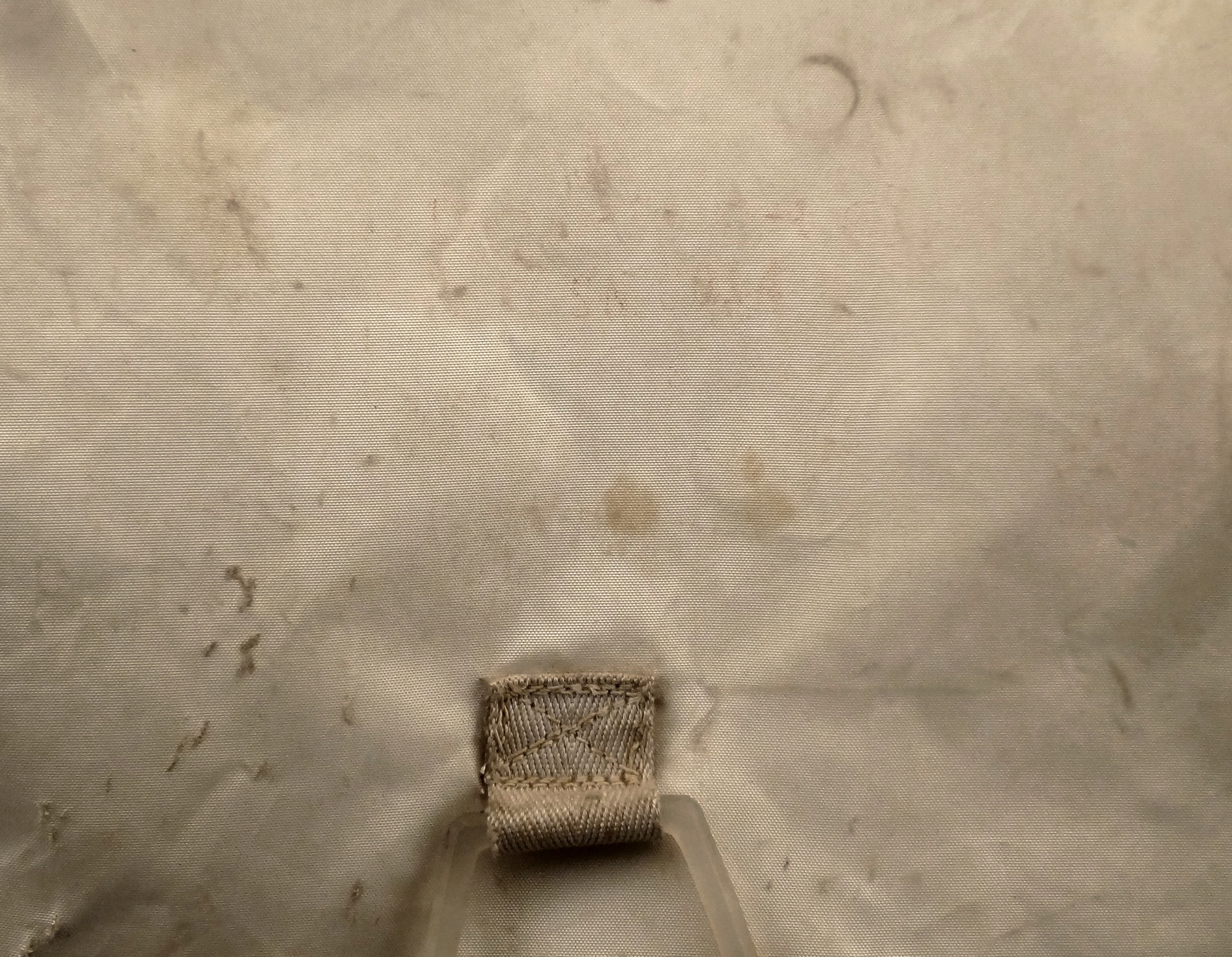
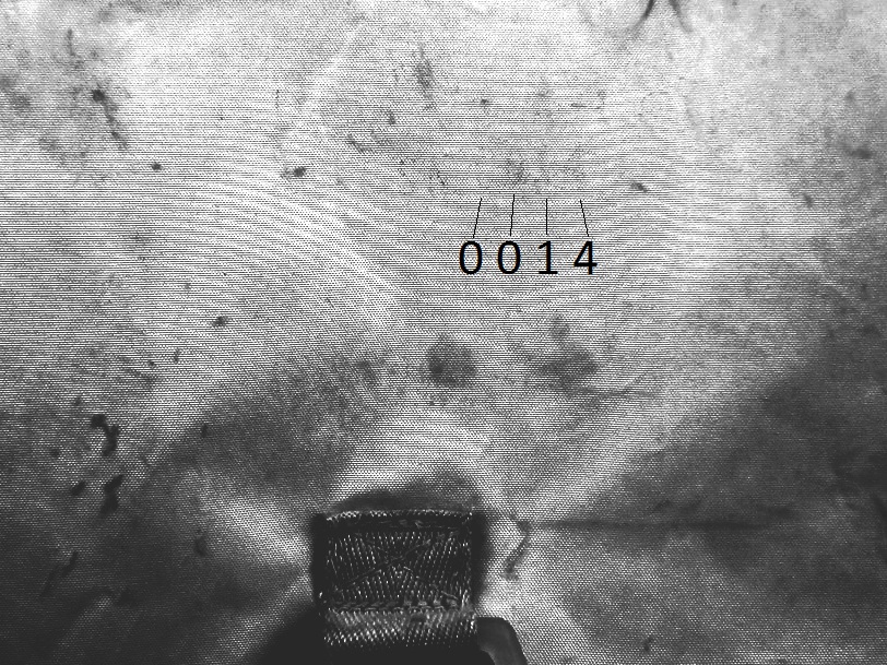
| At 109:16:49, while Neil
was getting lined up to go out the hatch for the EVA,
Buzz told him, "Your back is up against the
purse." This suggests that, when Neil re-entered
the cabin with his suit covered with dust that rained
down on him while he was using the Lunar Equipment
Conveyor (LEC), some of the dust may have adhered to the
back surface of the purse. Brian McInall notes that,
given the amount of dust they brought in on the suits,
there could well be be lunar dust on the surface facing
into the cabin. Allan Needell calls attention to the
serial number, S/N 0014, faintly visible above center in
this Lotzmann image. Ulli has provided an enhancement
and notes that the Apollo 12 Purse is S/N 0015. (Click
on the image for a larger version.) |
Additional Lotzmann Photos
(Click on the images for larger versions)
 |
 |
 |
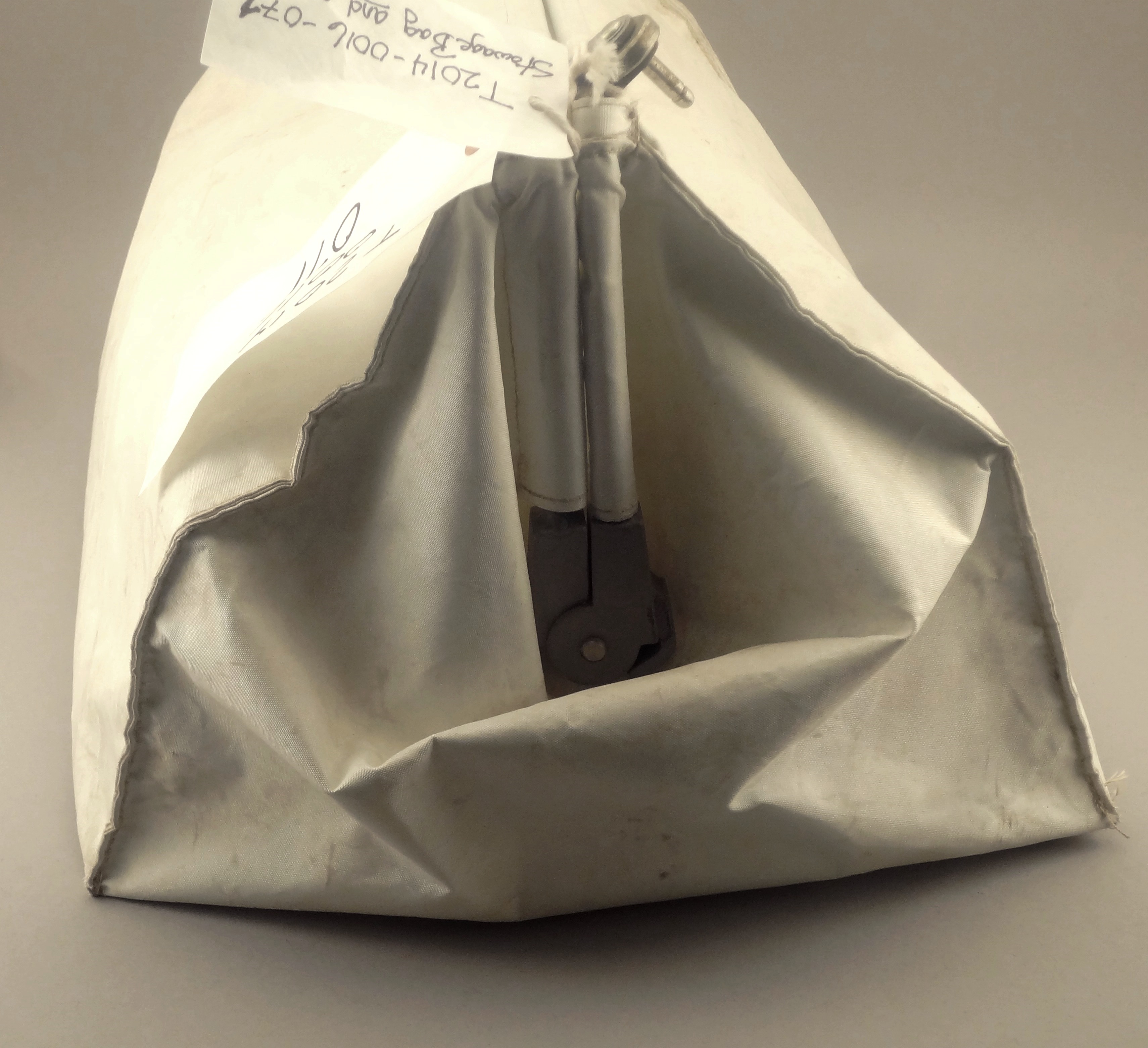 |
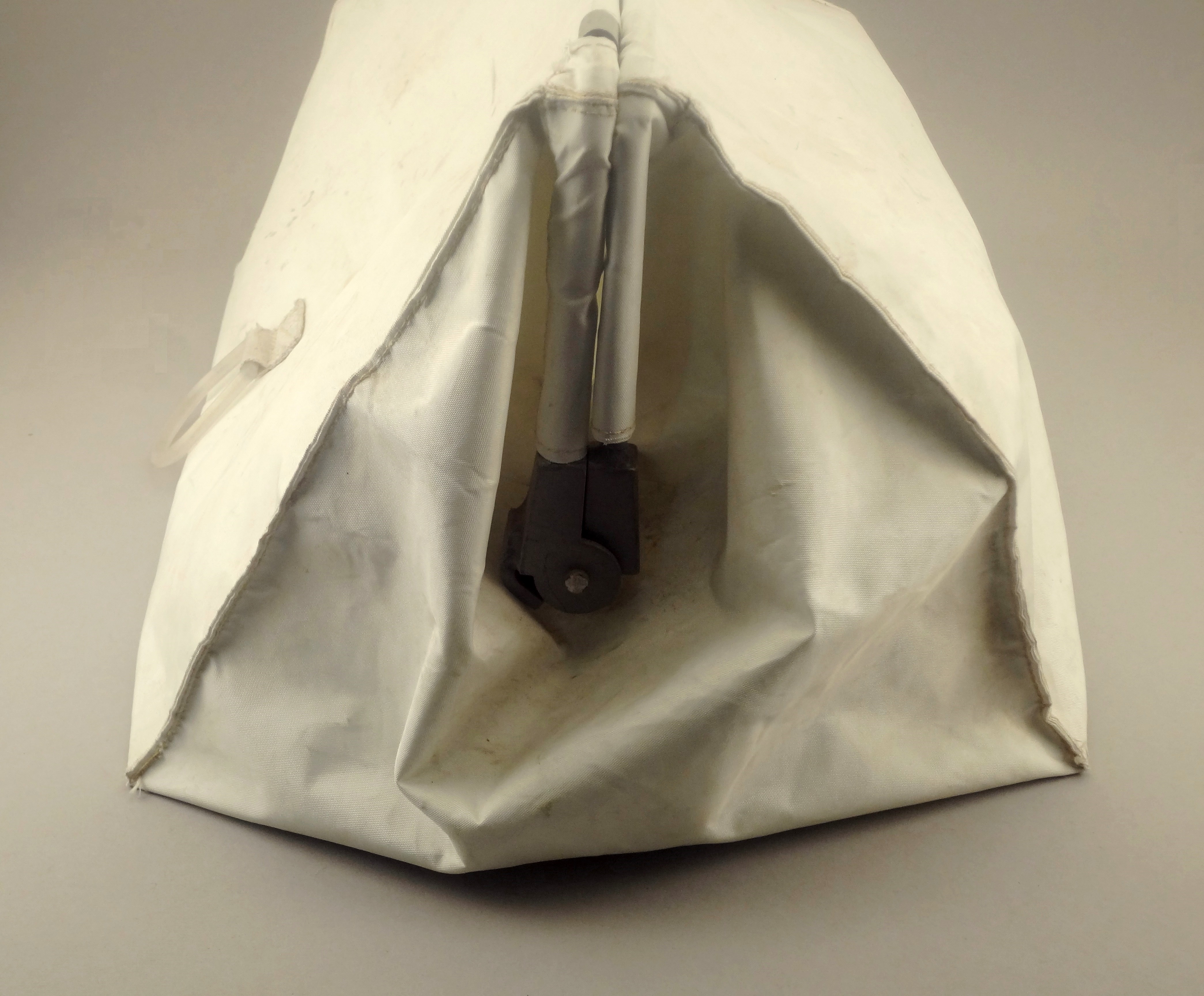
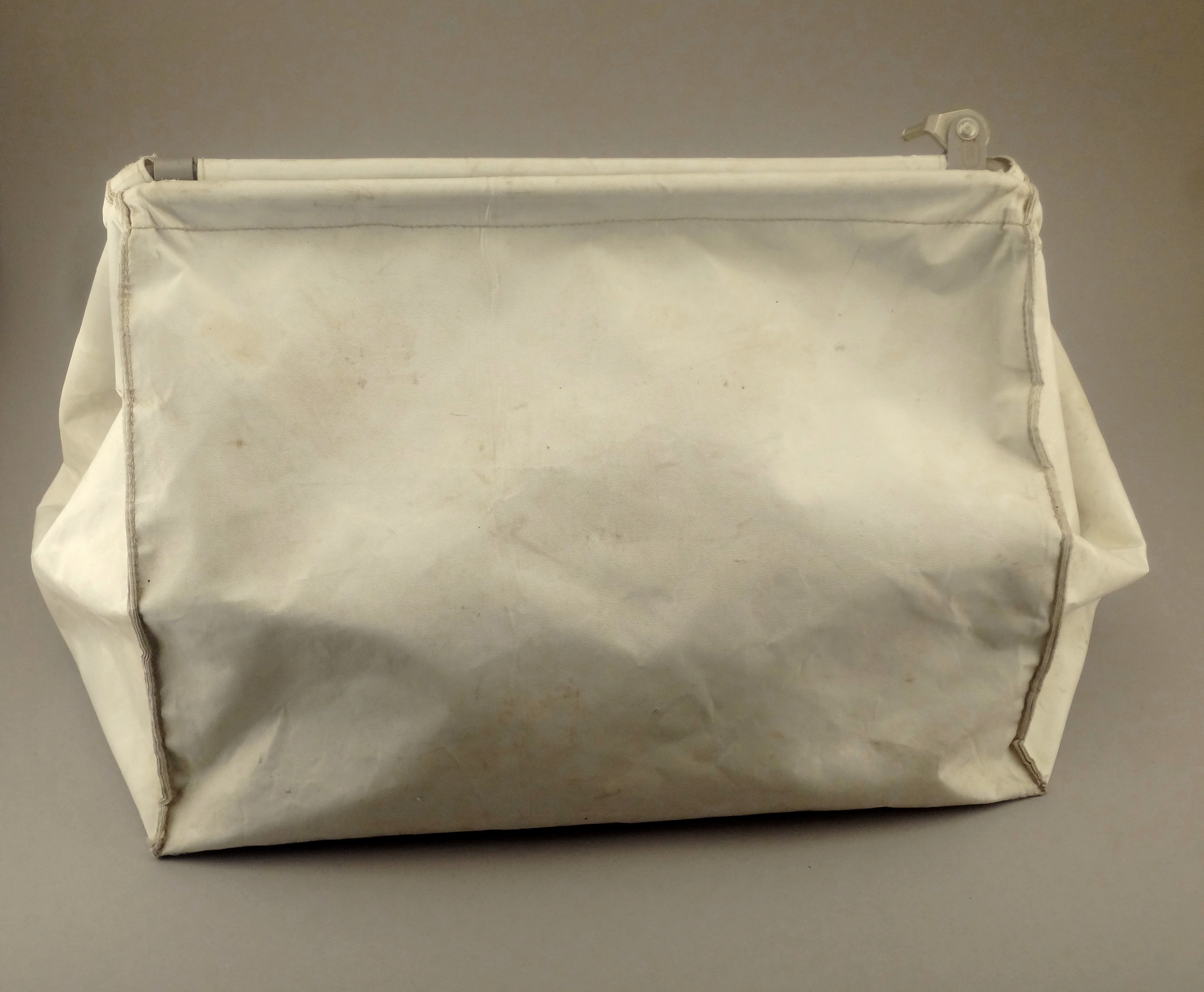
| Back side,
closest to forward bulkhead and hatch |
Left end,
with top closed |
Front side,
facing into the cabin |
Right end,
facing toward Aldrin's side of the cabin |
Return to Apollo 11 Lunar Surface Journal
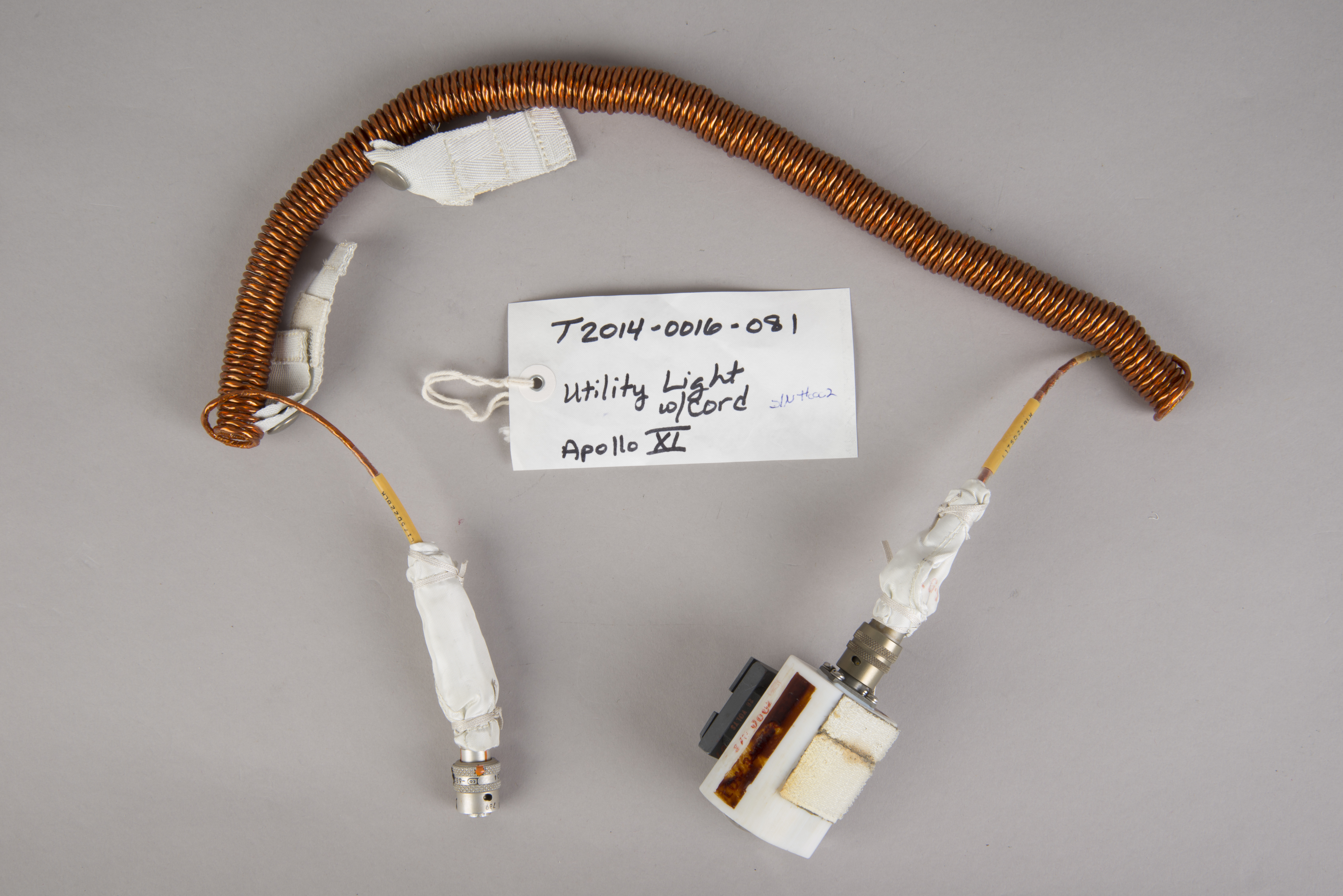
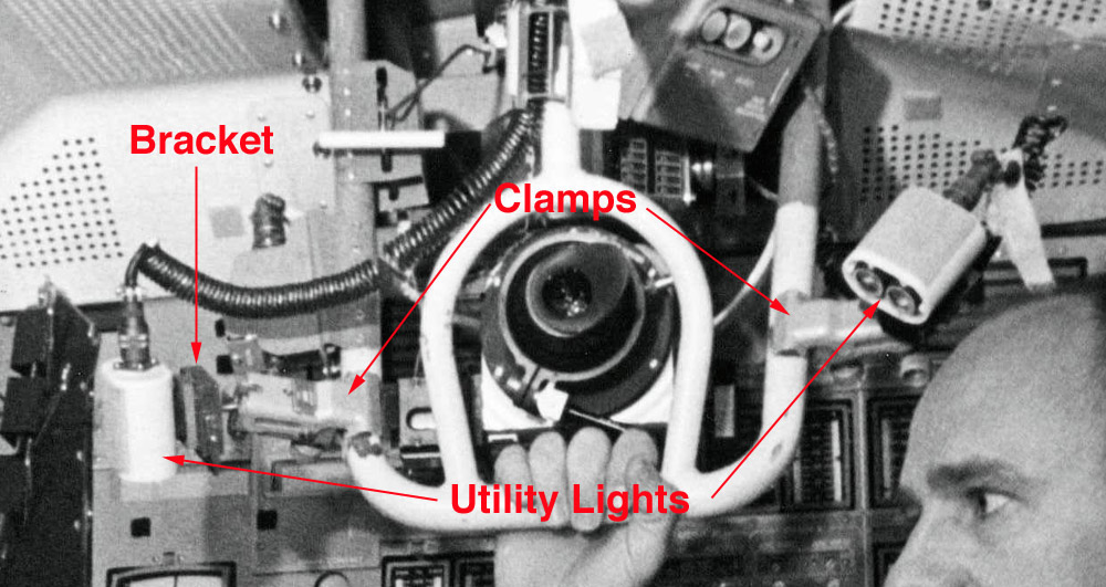
Utility Lights with Power Cables
| Detail from Apollo 11
training photo S69-38678
showing Neil in a LM simulator. One of the two
utility lights is attached to the yellow Upper
PLSS Mounting Station Pin recessed in the
ceiling above his head. The other is out of the
field-of-view to the right. A labeled version of AS11-36-5390
shows one of the utility lights sticking out of the
Interim Stowage Assembly (ISA) which was attached to the
Alignment Optical Telescope during the trip out from
Earth. |
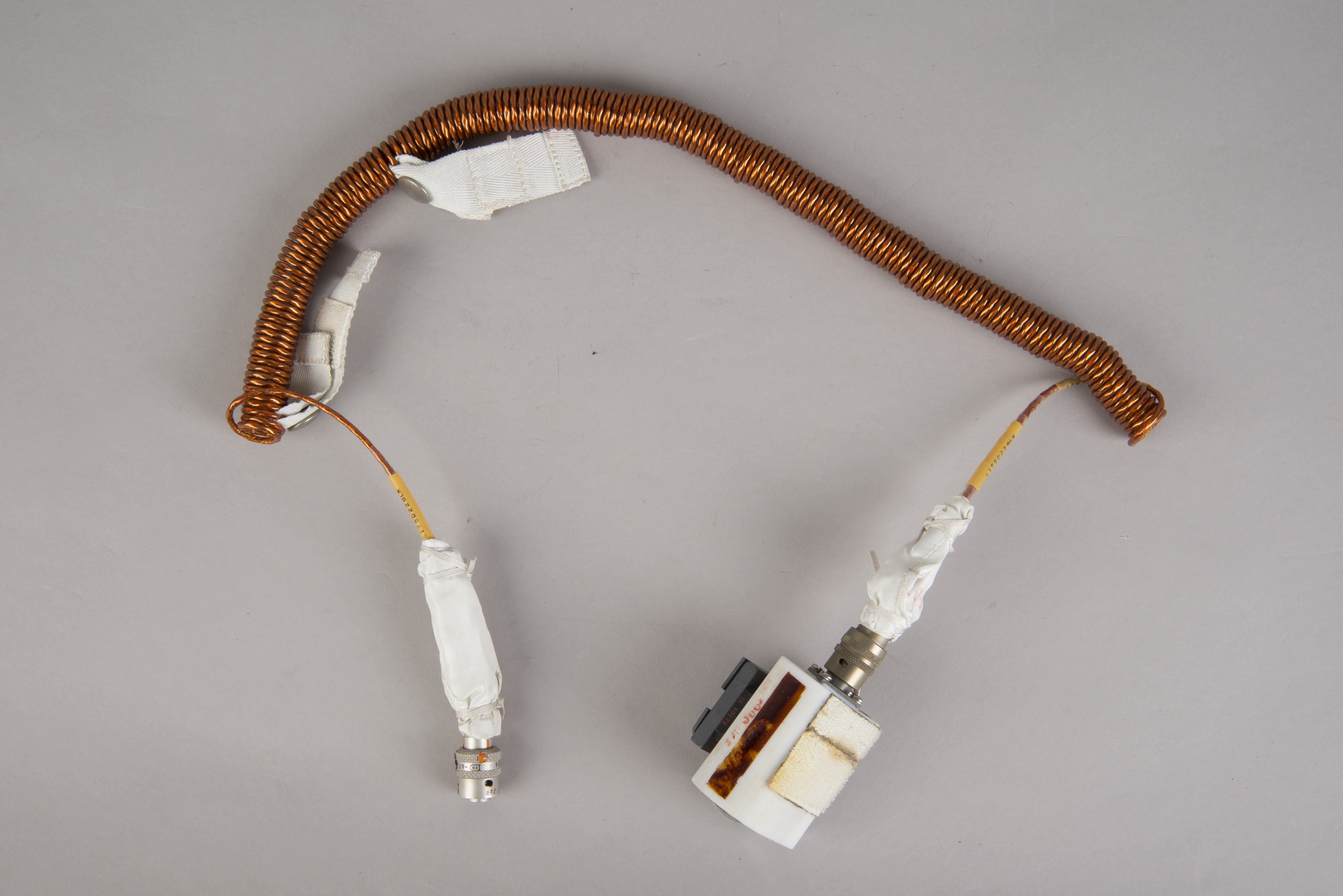
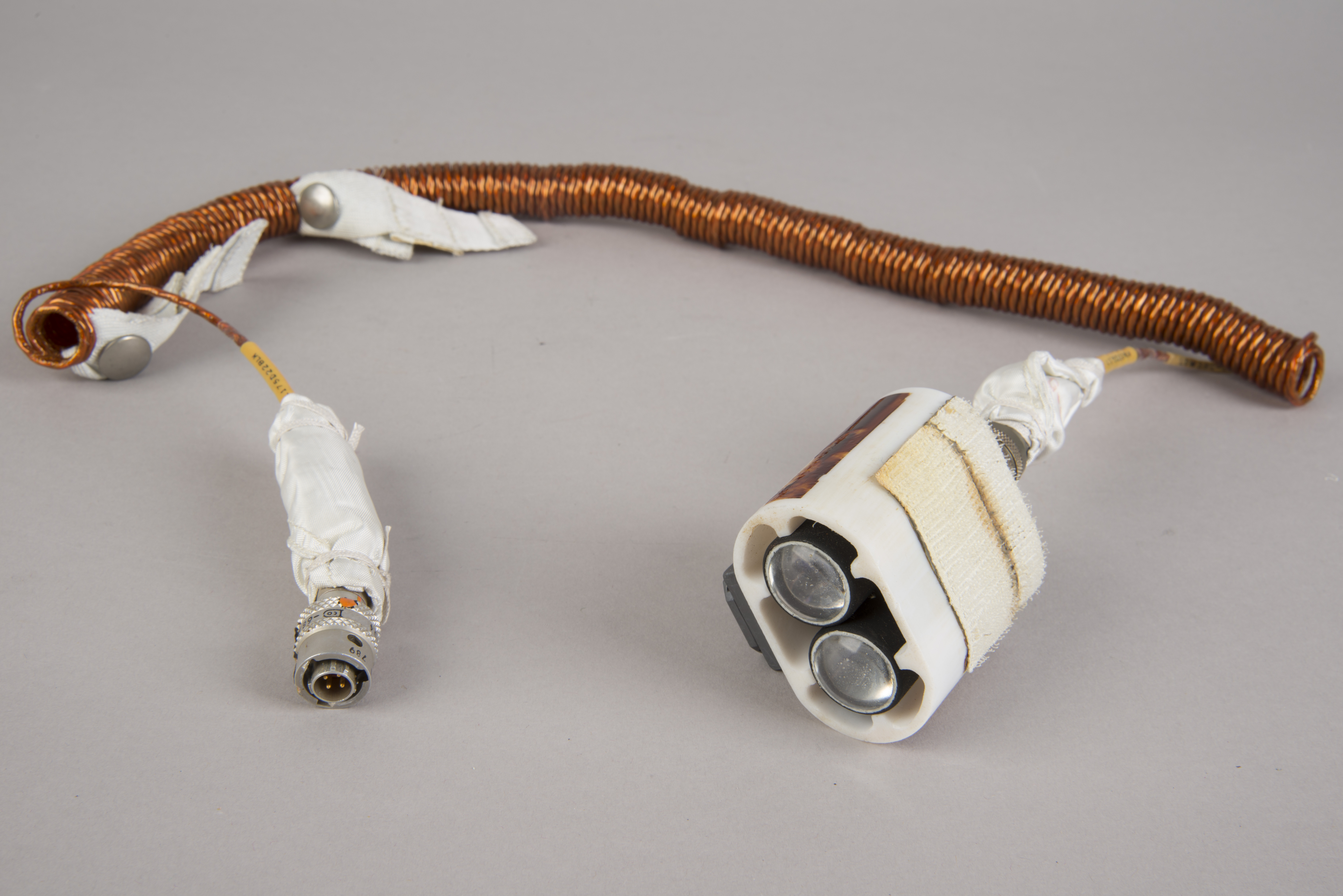
Utility Light S/N 0001
 |
 |
 |
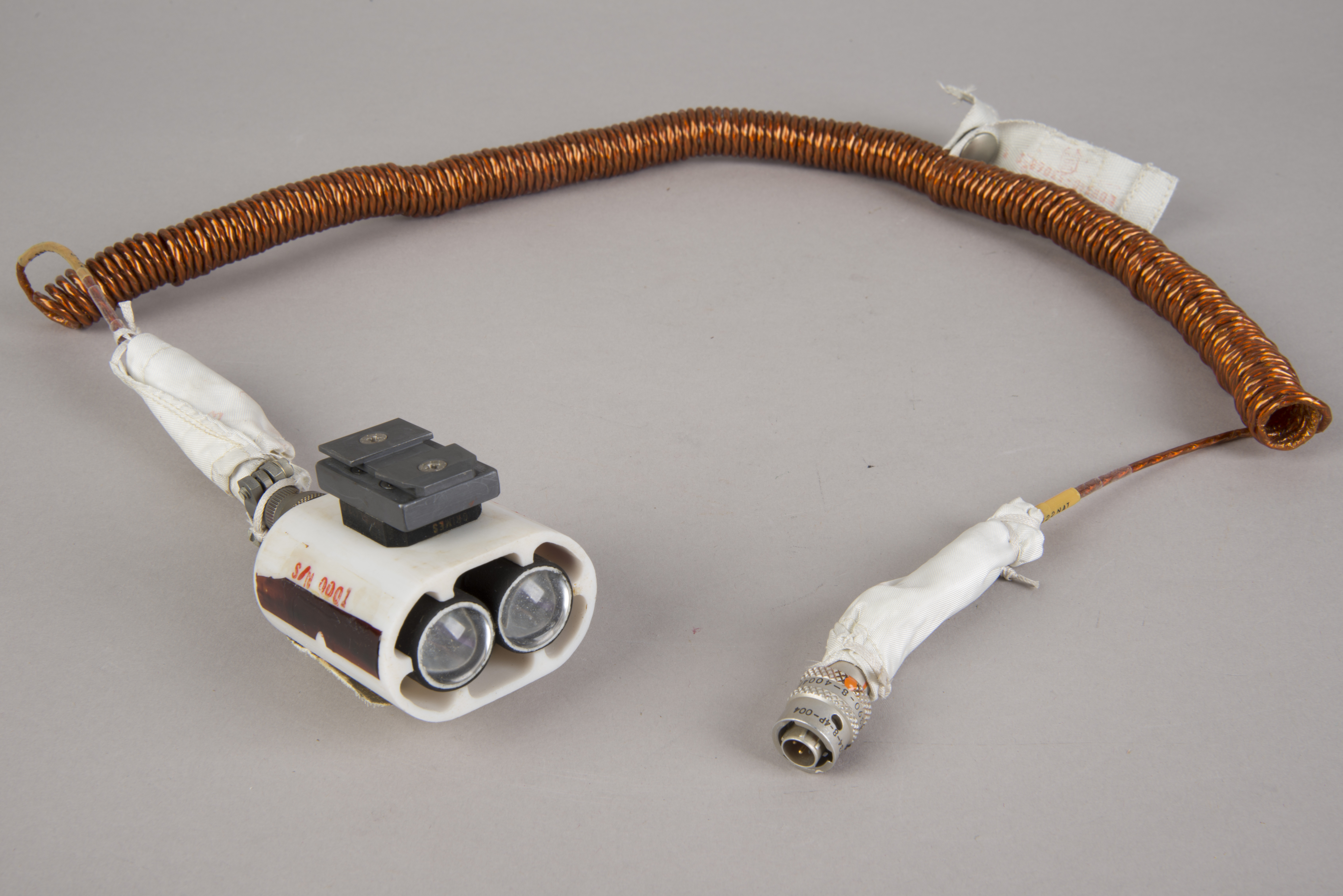 |
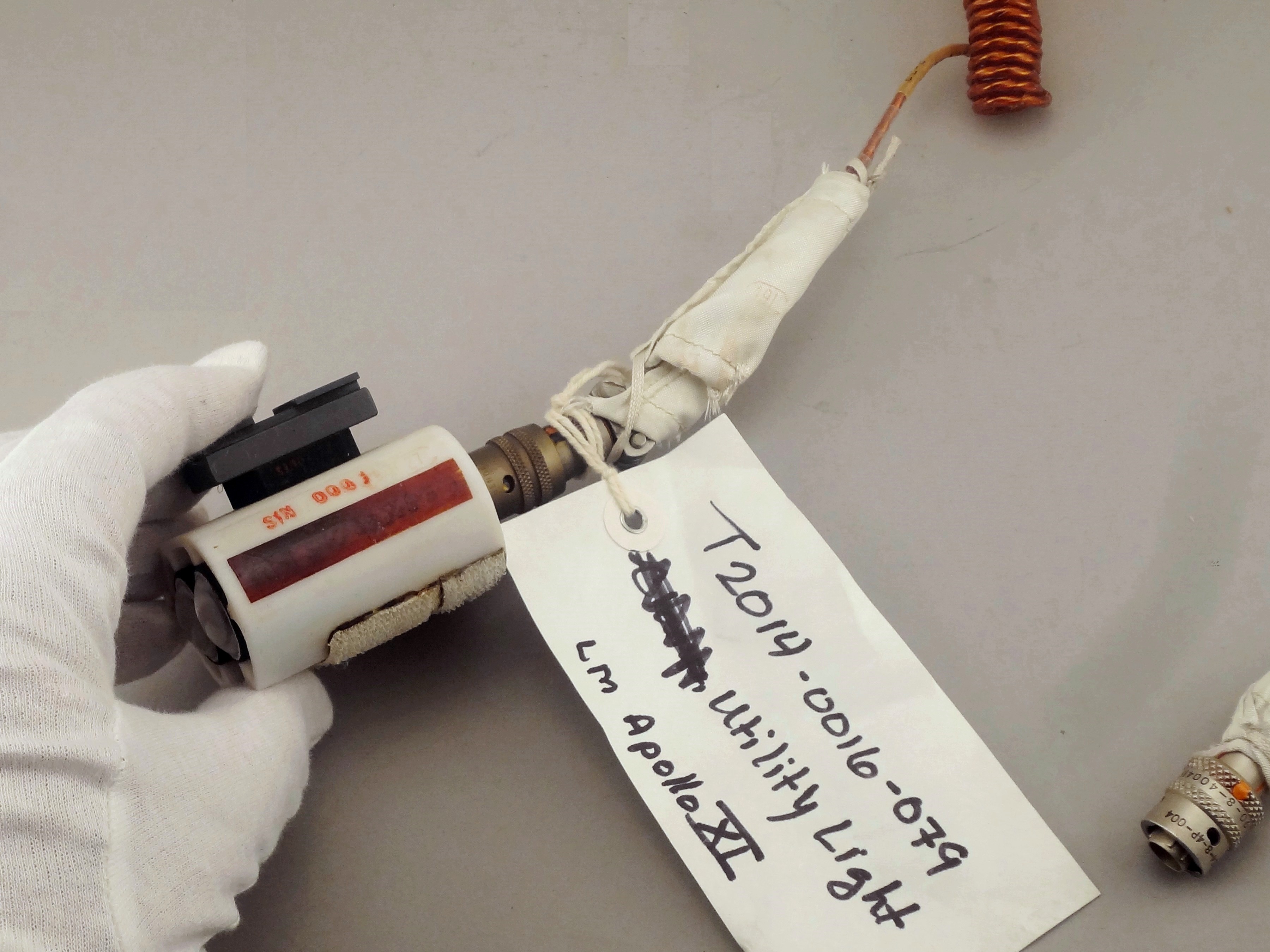
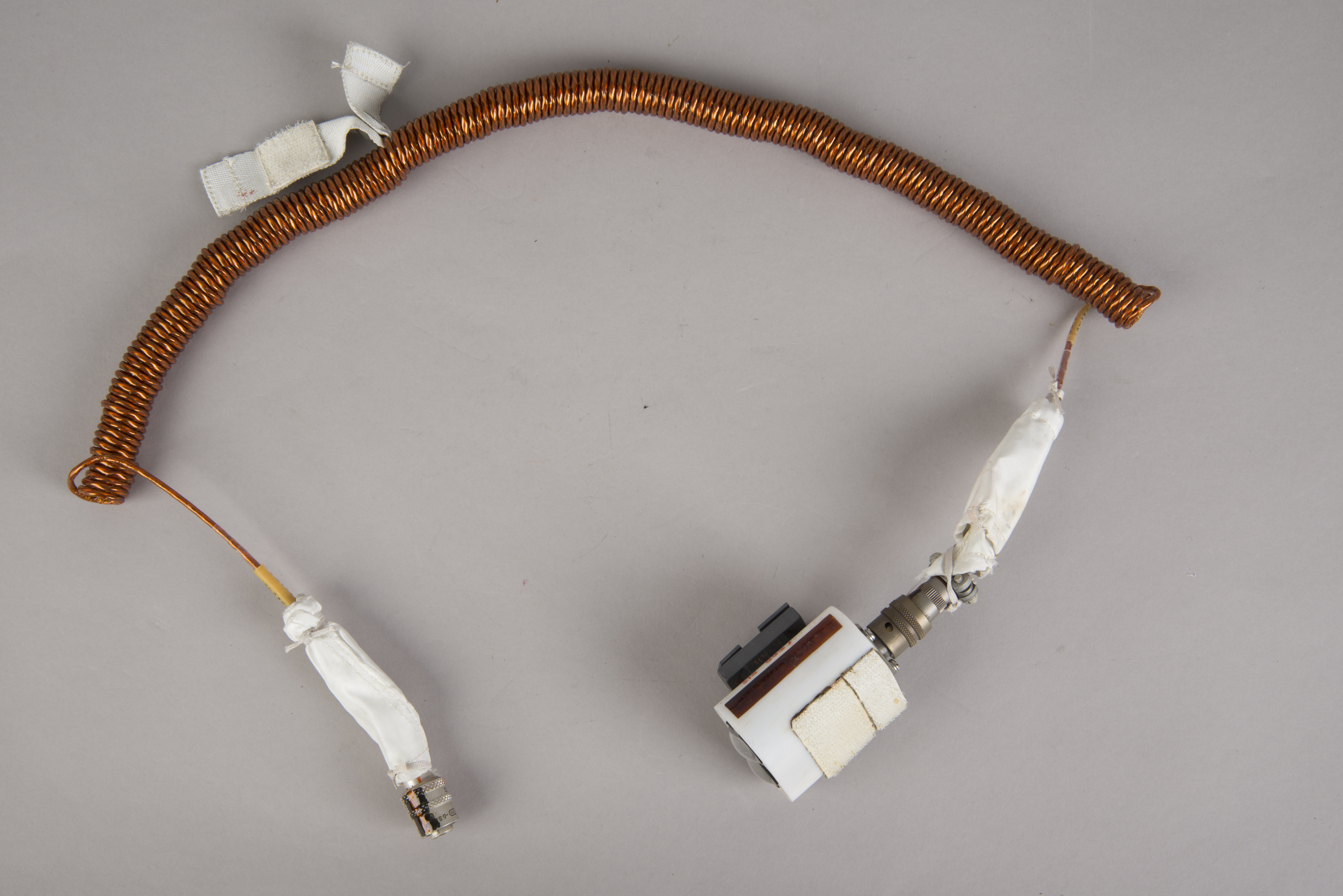
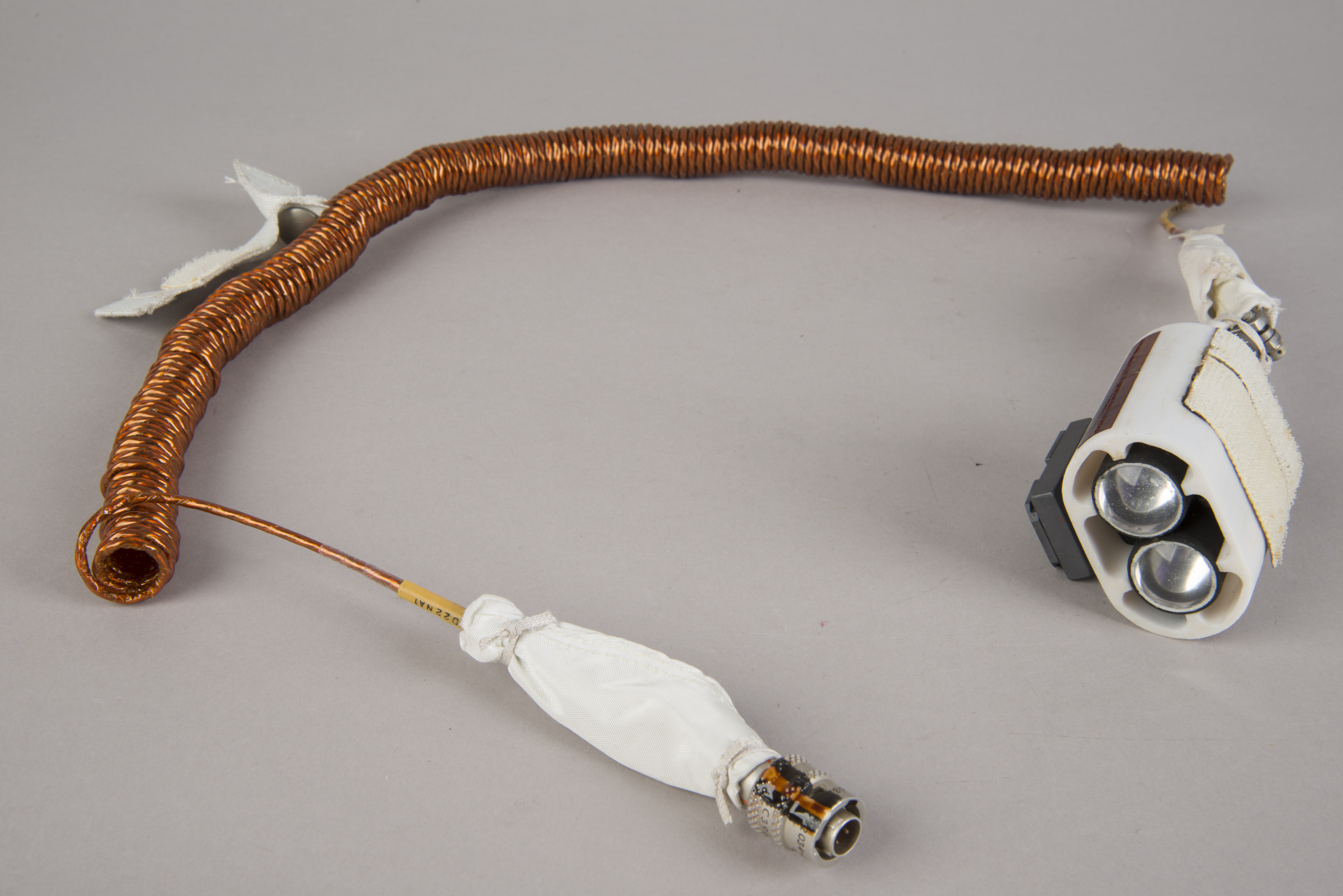
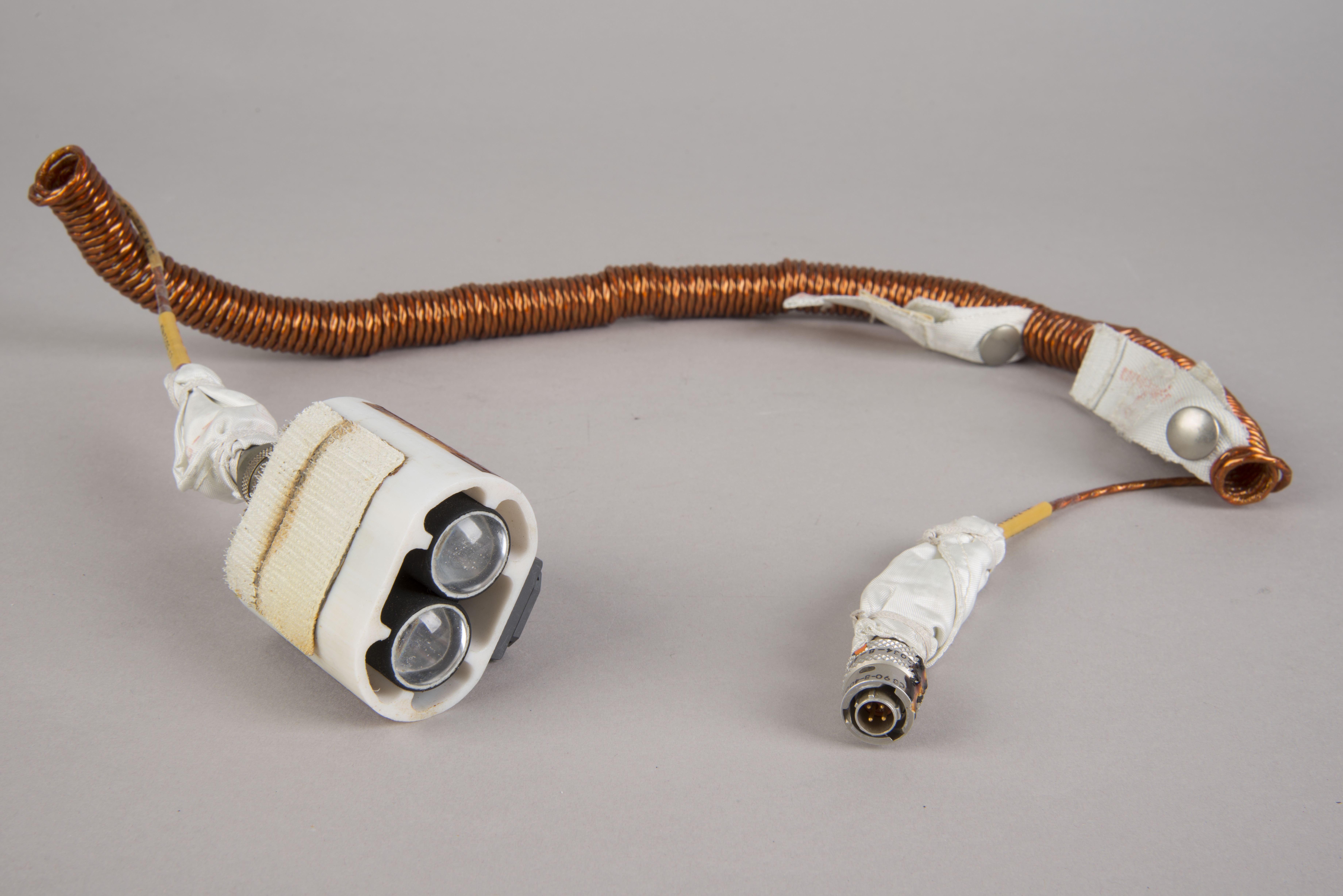
| S/N 0001 is the Utility
Light which, when removed from the Purse at the
Armstrong home, had a Utility Bracket Assembly
(sometimes called a Utility Clamp) attached. Photo used
with permission. The Velcro patches on the top surface
of the light would have allowed placement in locations
where there were no good attachment points for the
bracket. During the launch from Earth, the utility
lights, cords, and brackets were stowed in the Interim
Stowage Assembly (ISA) in the LM cabin. Lotzmann
photograph at upper left; others National Air and Space
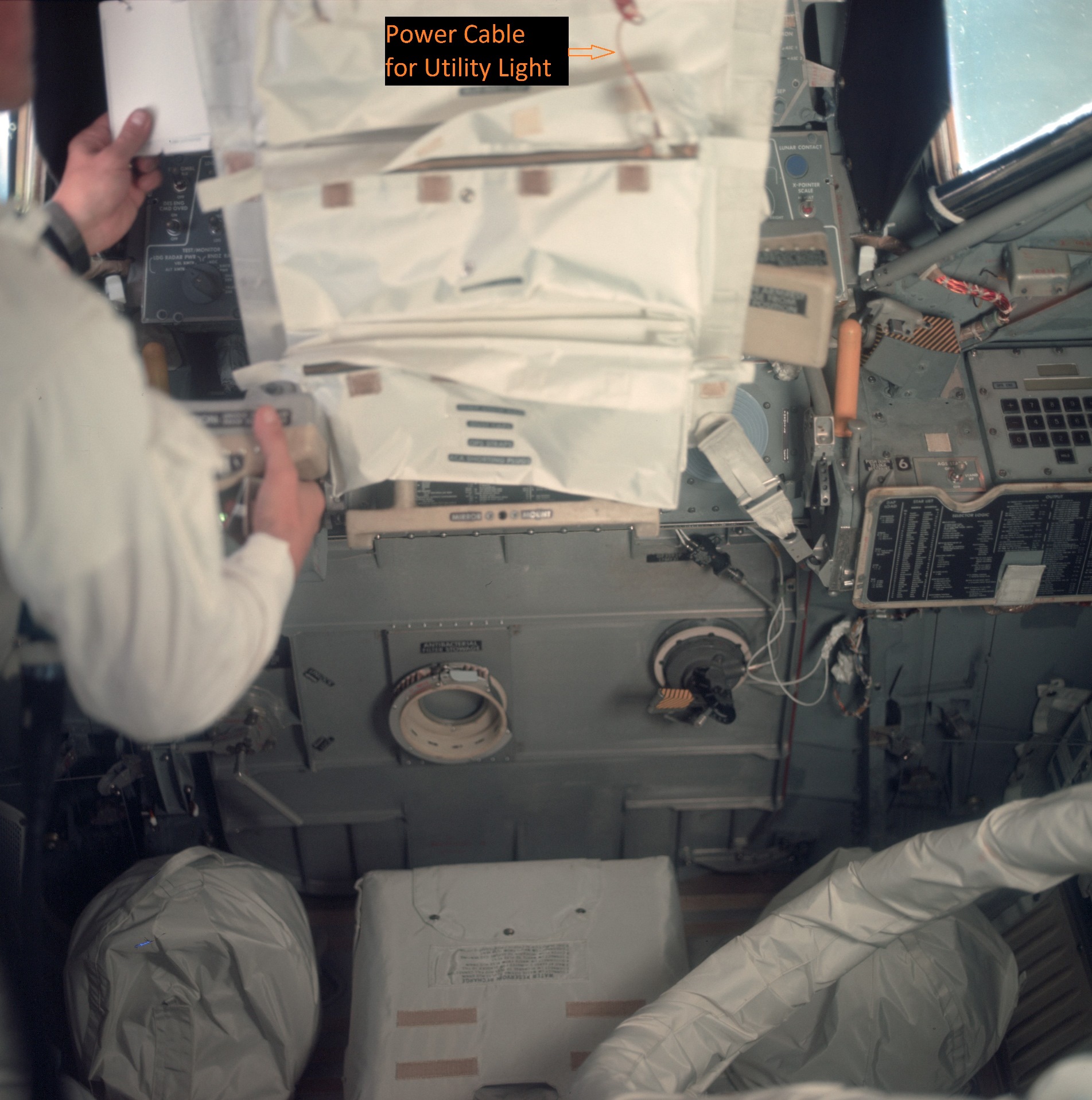
Museum Conservation Photographs. A labeled detail from AS11-36-5399
shows part of one of the utility light power cords
sticking out of the ISA. (Click on the images for larger versions.) |
Utility Light S/N 0002
 |
 |
 |
 |
| Utility Light S/N 0002.
National Air and Space Museum Conservation Photographs. (Click on the images for larger versions.) |
Return to
Apollo 11 Lunar Surface Journal
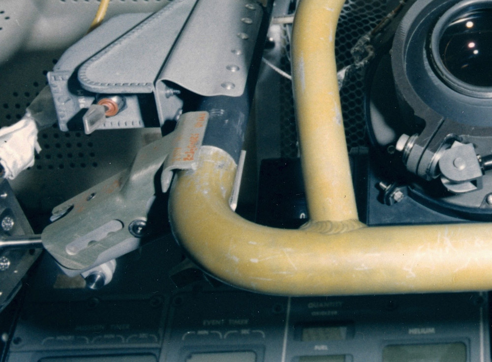
Utility Bracket Assembly
| There were two bracket assemblies available
for use with the DAC or the Utility Lights. During
the trip out from Earth, they were stowed in the Interim
Stowage Assembly (ISA) attached to the Alignment Optical
Telescope Guard at the front of the cabin above the main
instrument panels. The ISA was later moved when the
crew prepared for undocking from the Command Module. As
labeled in the Apollo 12 training photo below, each
Bracket Assembly had a clamp at one end which could be
loosened or tightened with a thumbscrew. At the
other end was a female bracket - rather like shoe-type
brackets used to attached flash units to cameras - which
could be fitted to a male fitting on a Utility Light or on
the Data Acquisition Camera (DAC). |
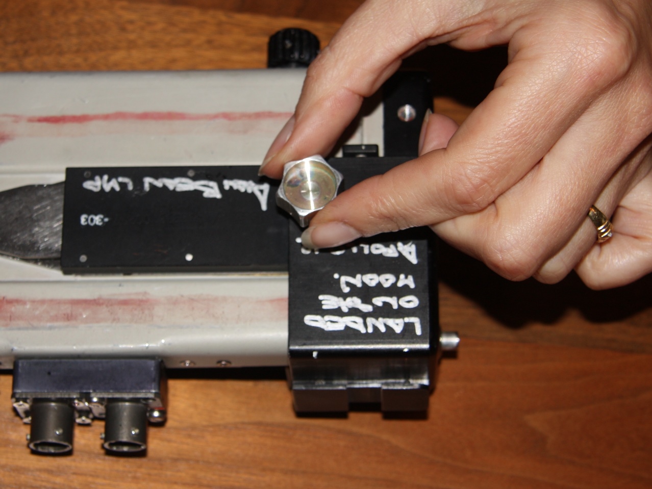
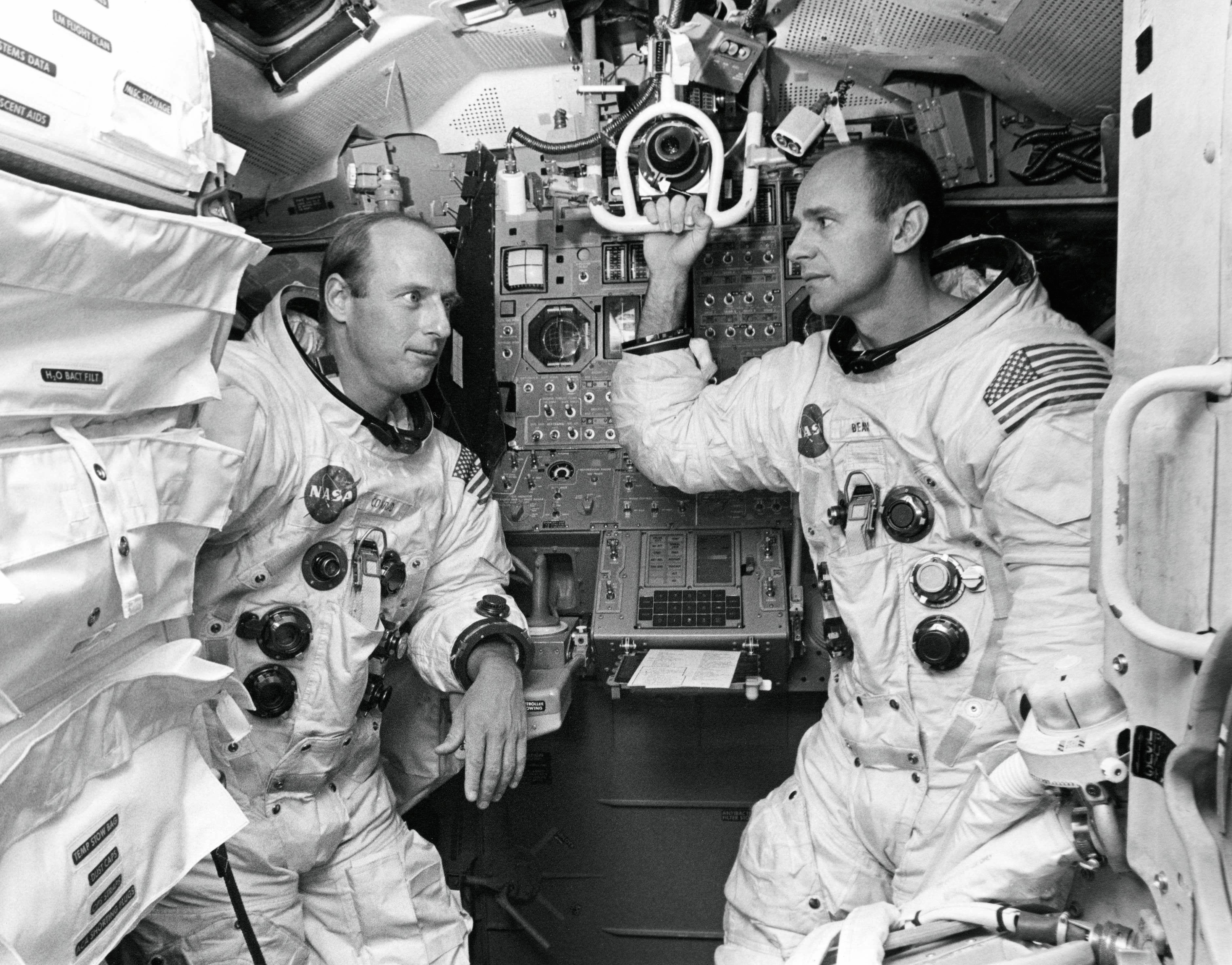
| Detail from a posed
training picture, ap12-69-H-1676,
showing Alan Bean in a LM simulator on 21 October
1969. The two Utility Lights are clamped to the
AOT (Alignment Optical Telescope) guard. |
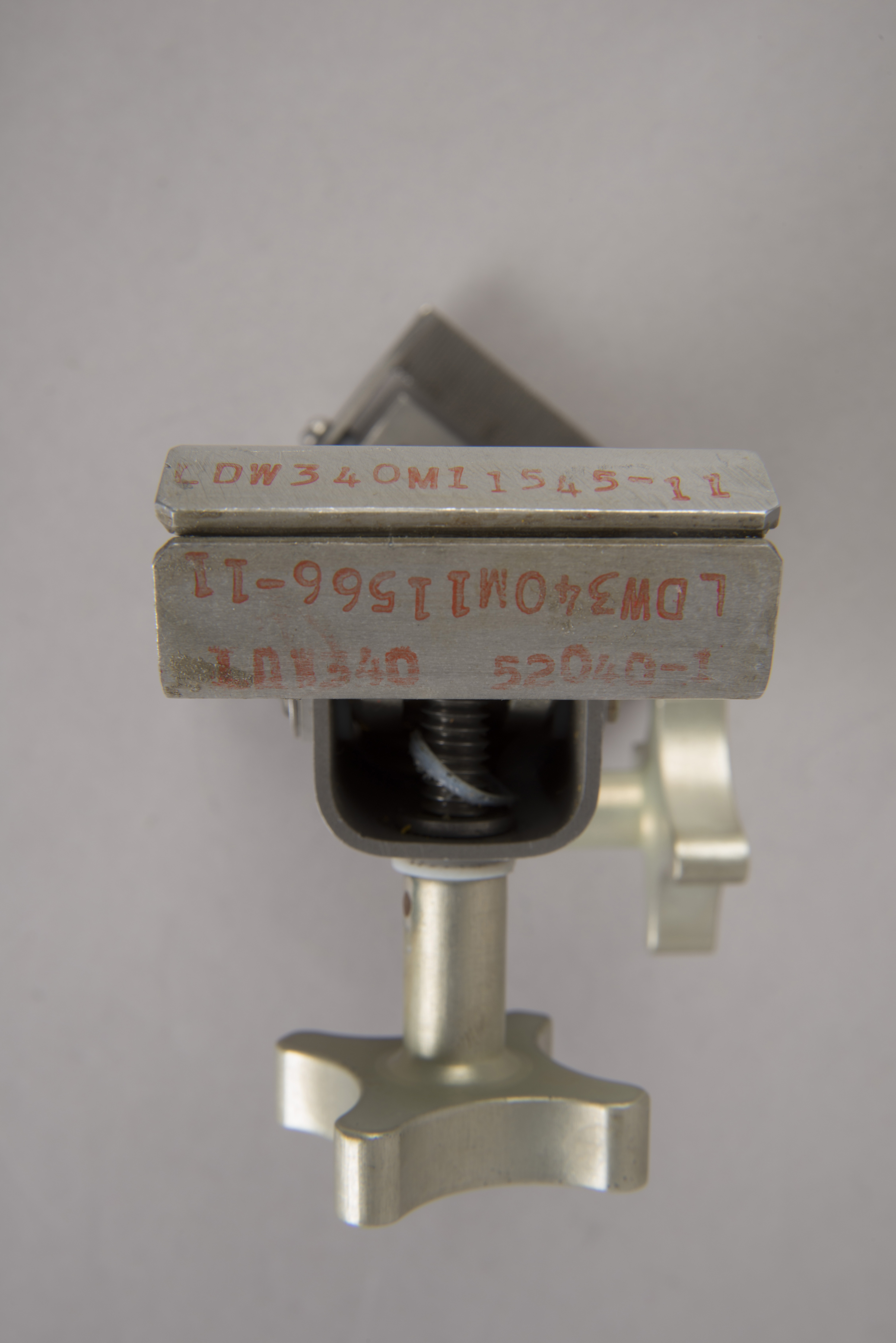
Utility Clamp (L)DW-340M11545-11 / Bracket LD-340-53051-3 /
Inspection Stamp 651
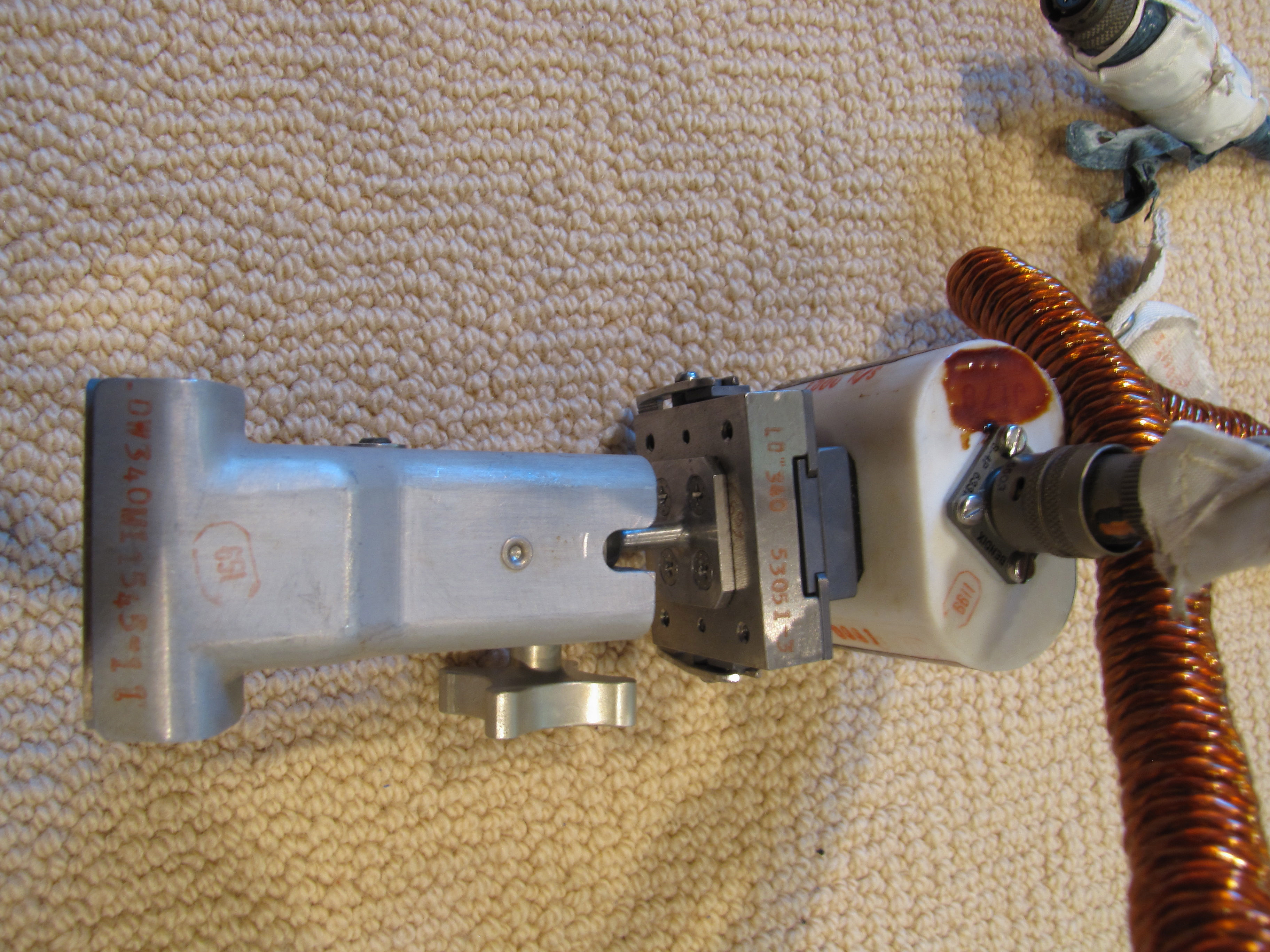
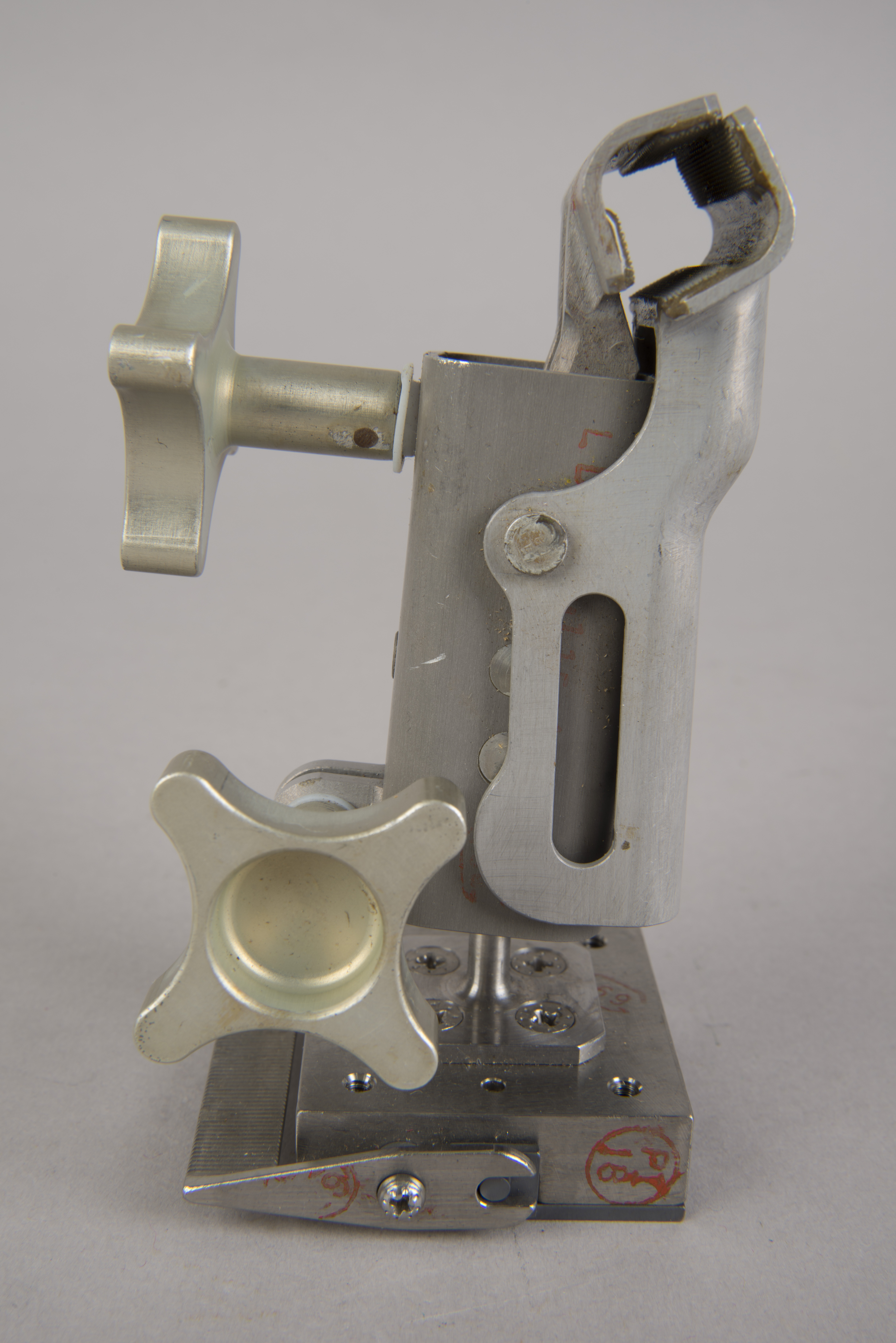
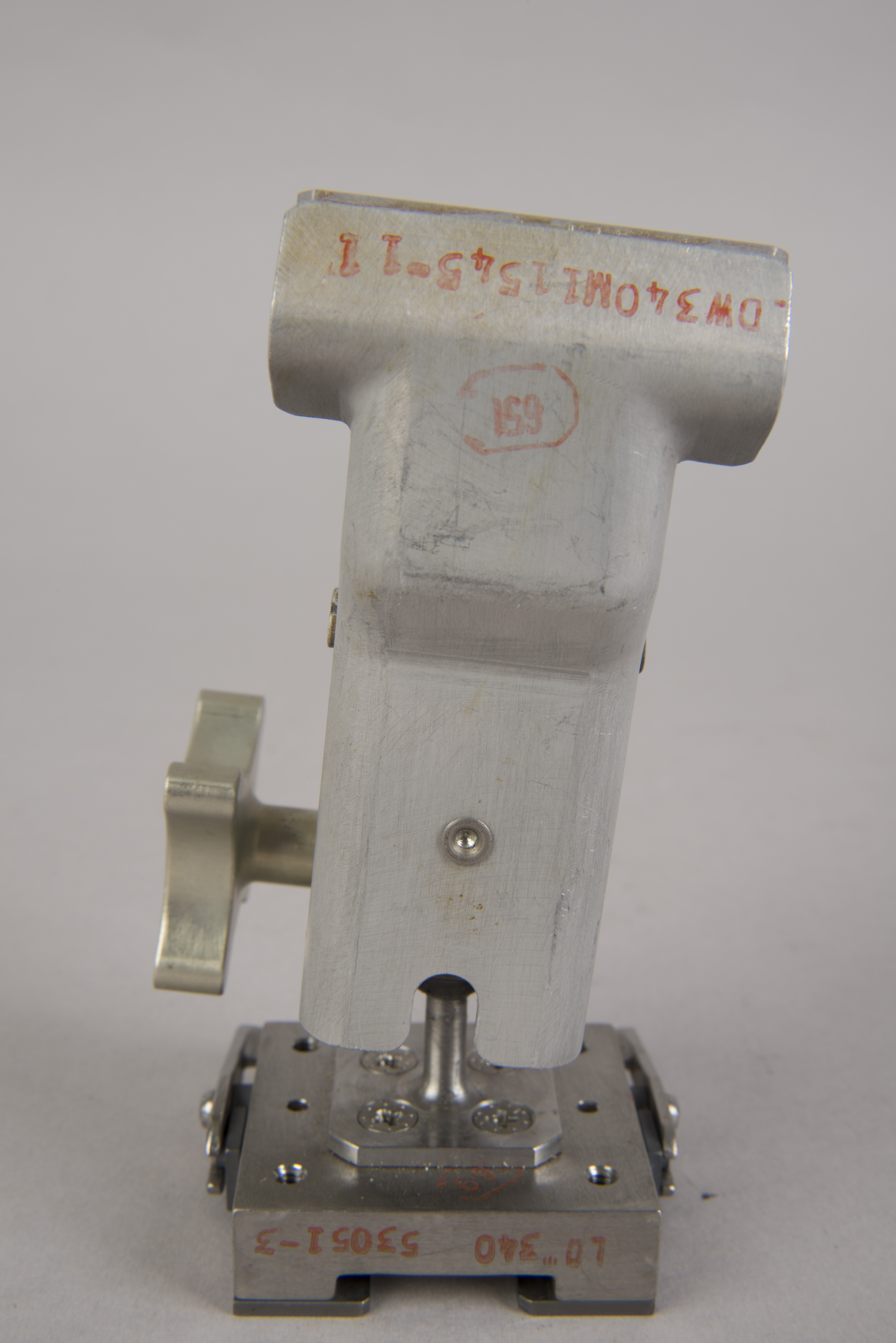
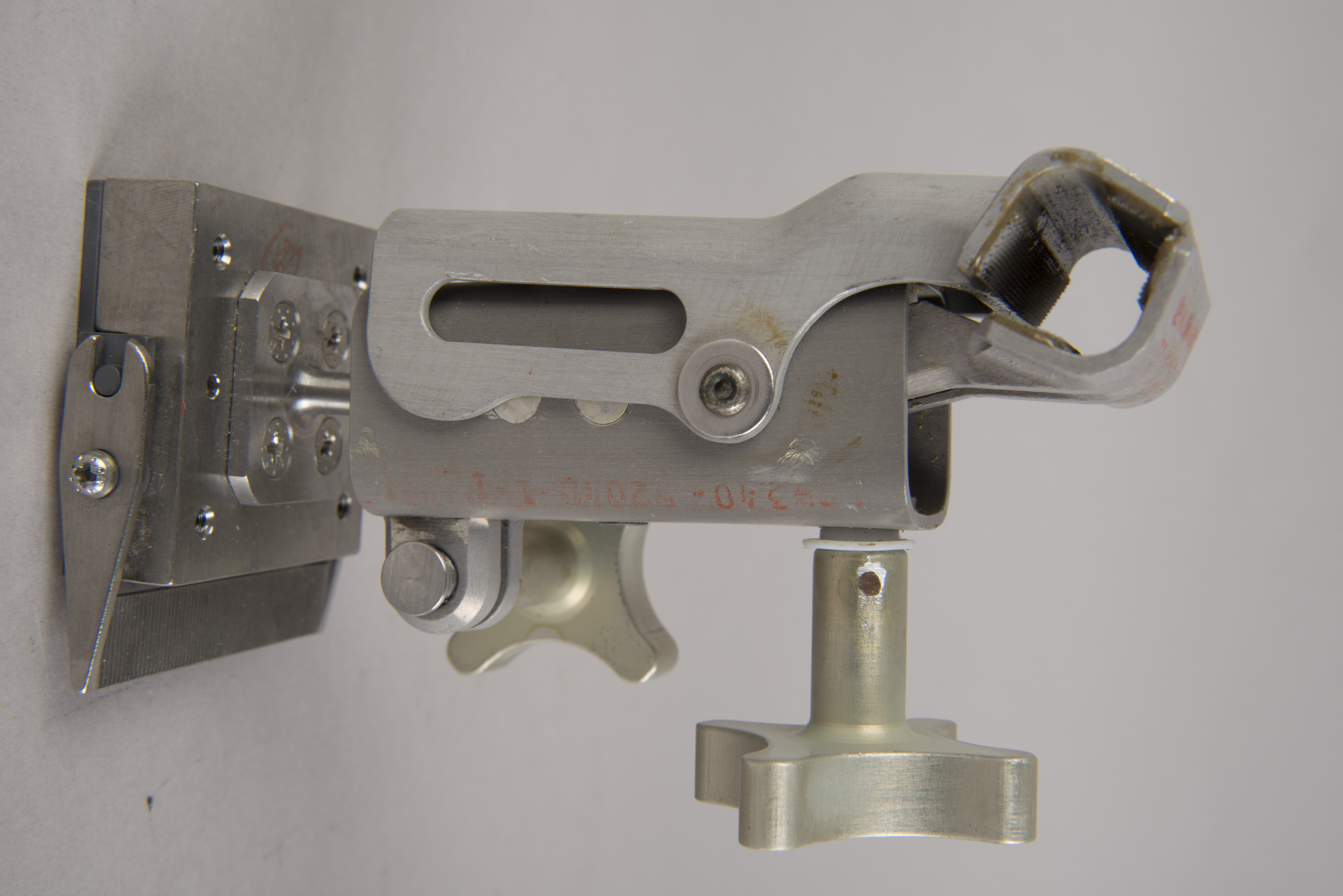
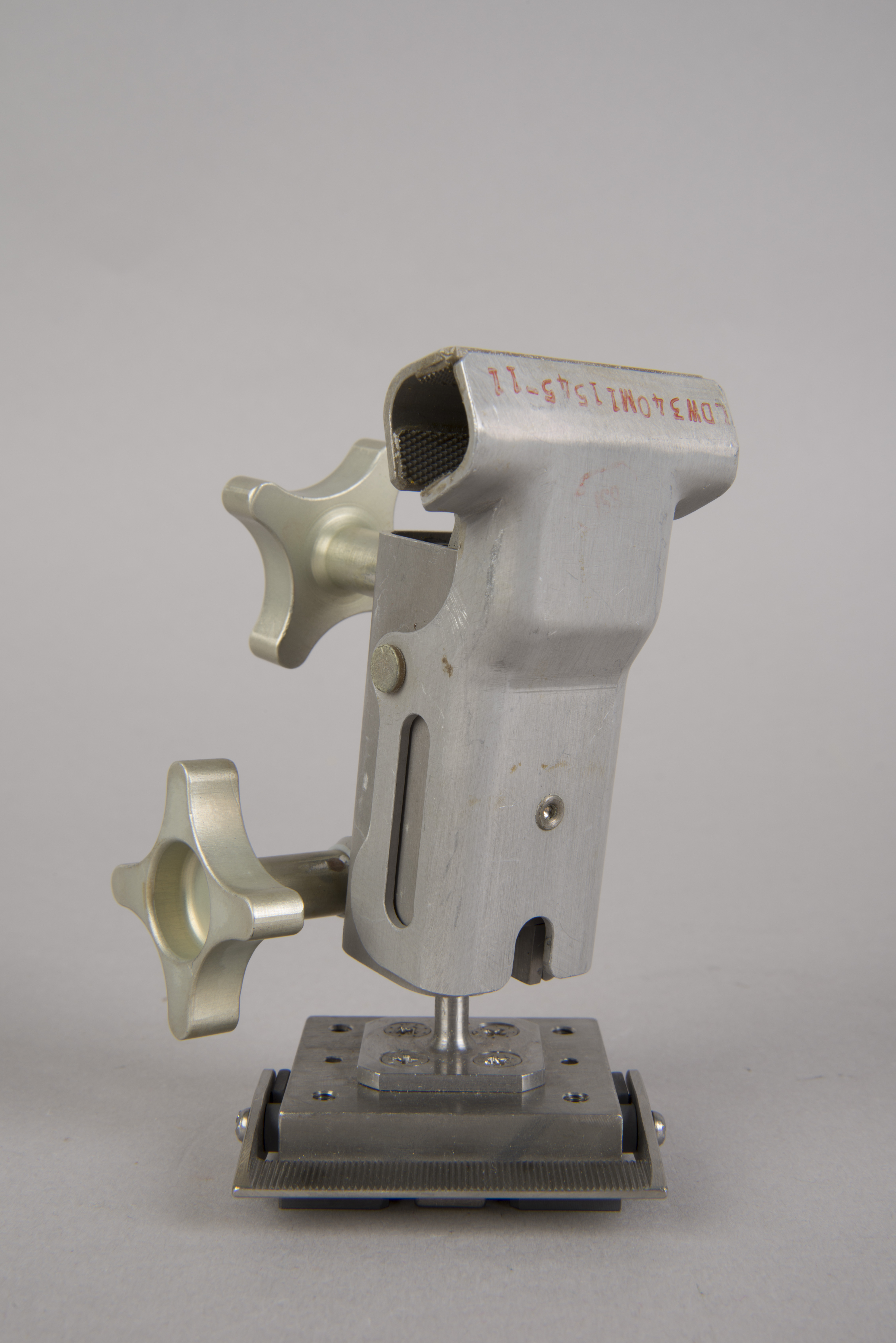
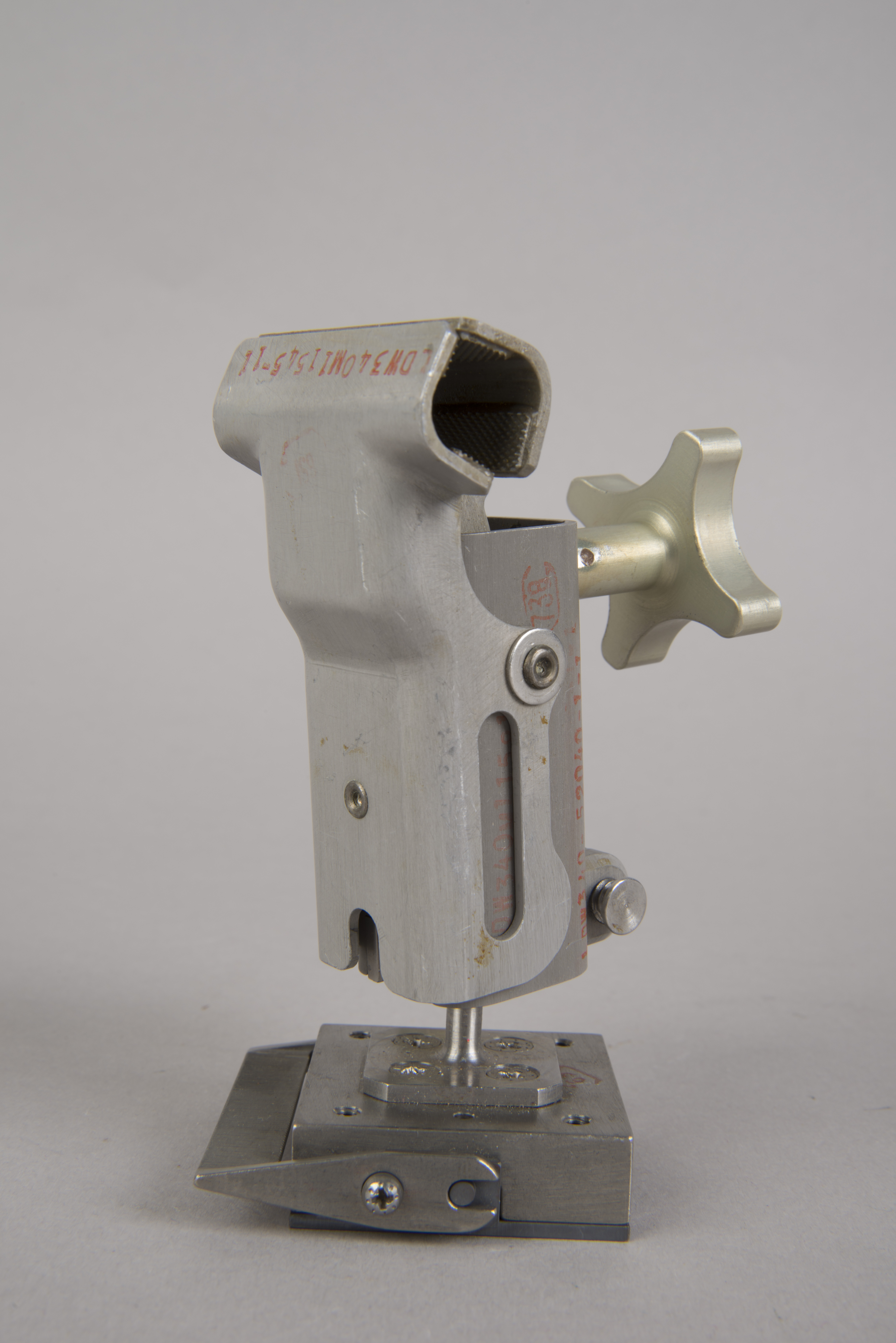
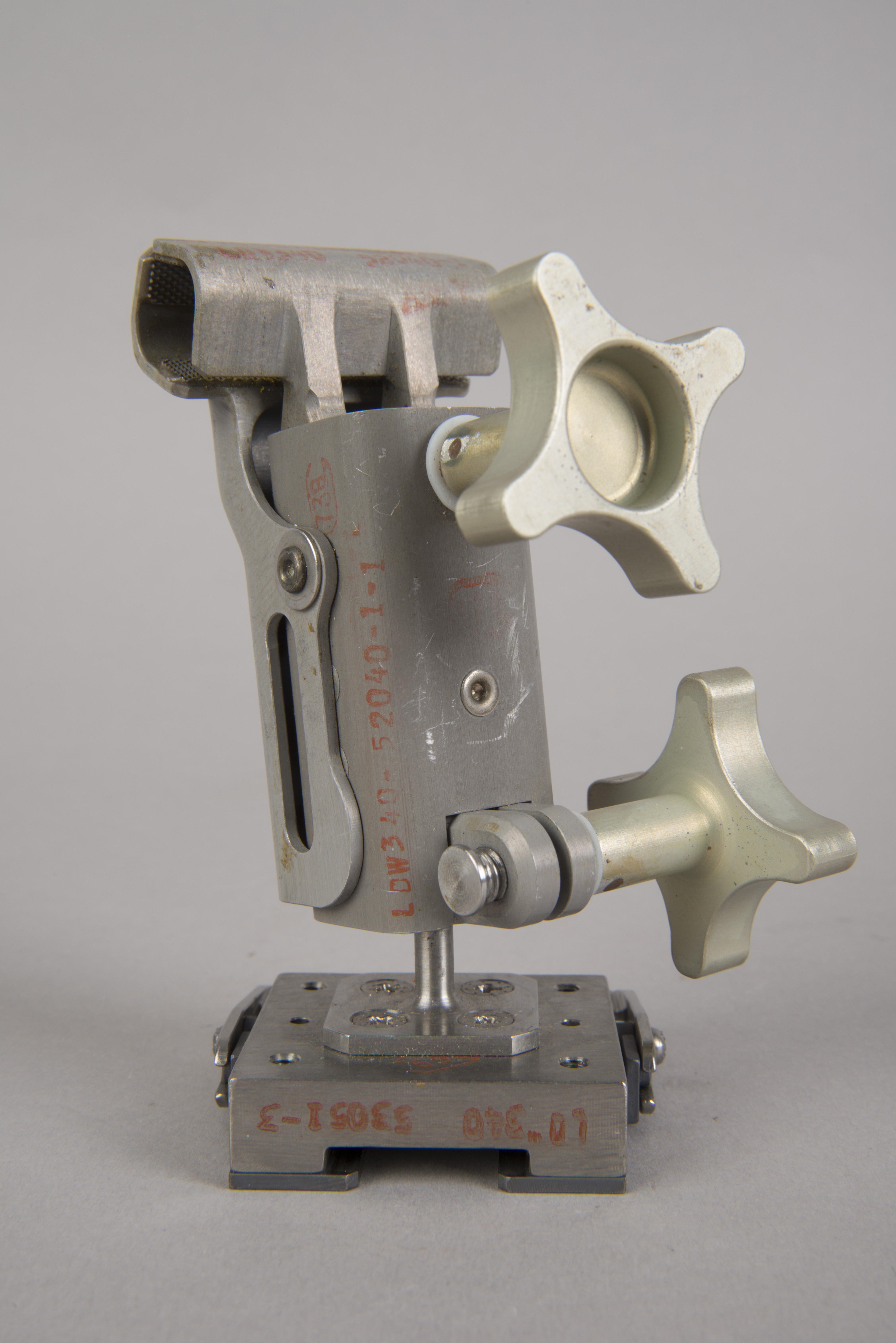
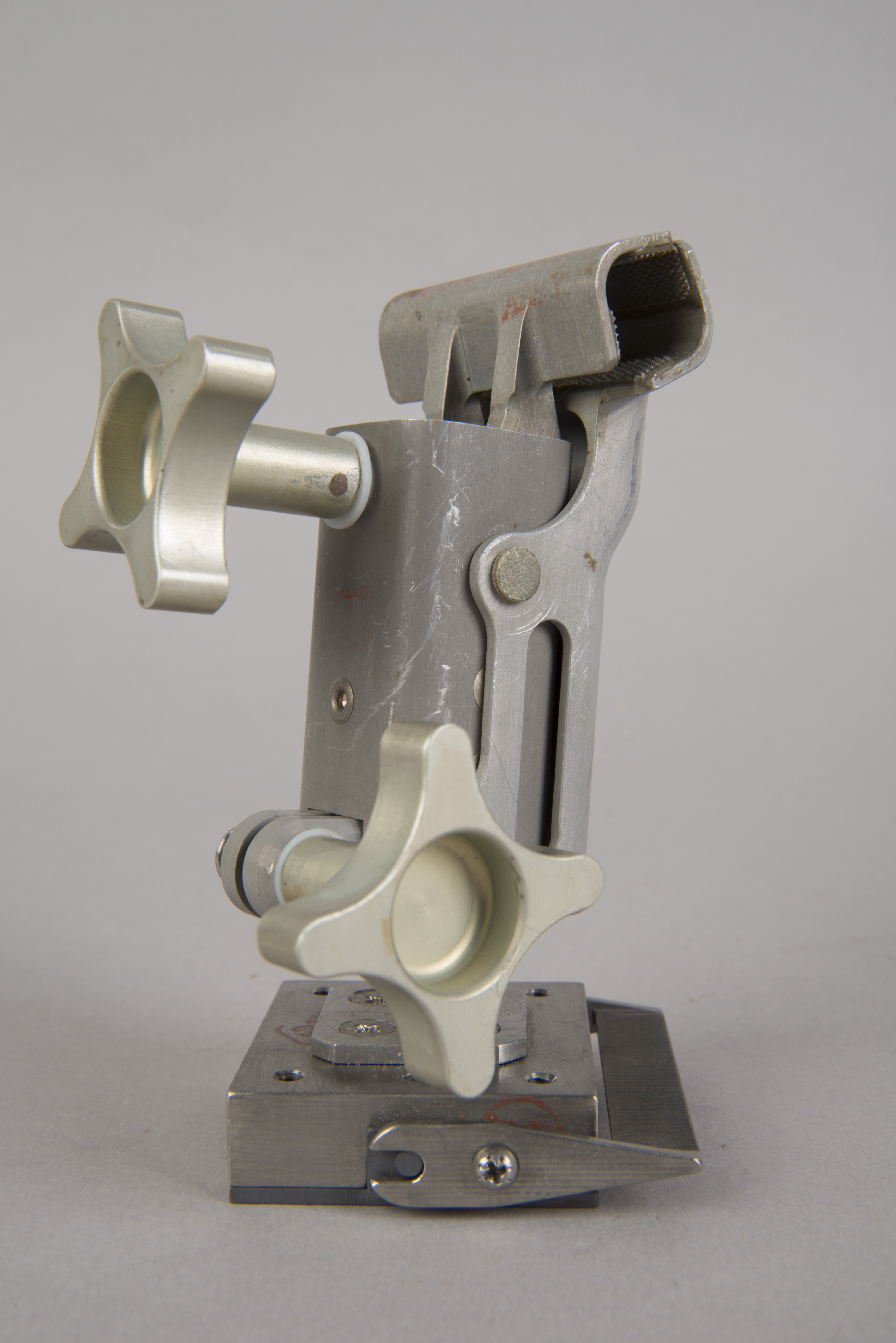
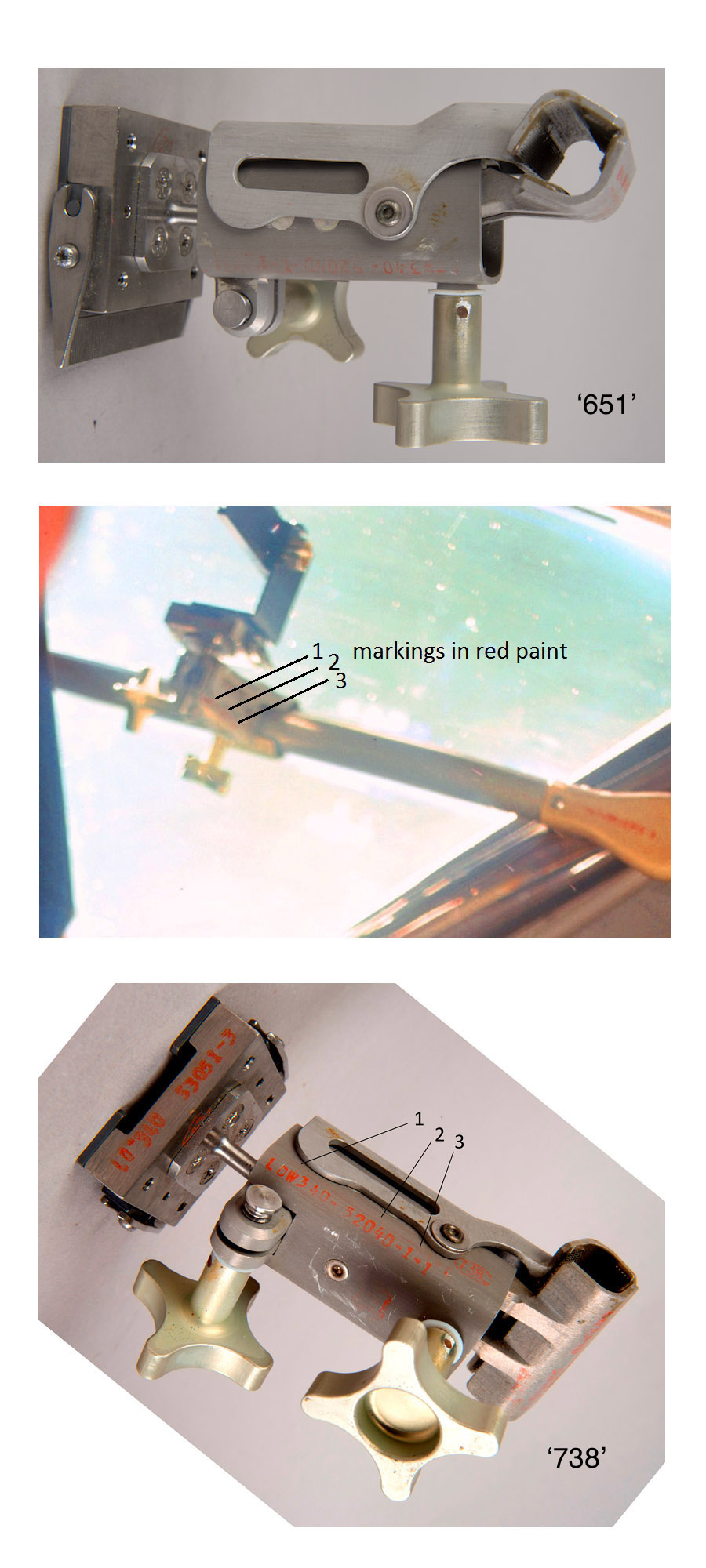
| This Utility Bracket
Assembly was attached to Utility Light S/N 0001 when
photographed in the Armstrong home. It can be
distinguished from the other Bracket Assembly because
(1) the vertical portion of the "L" in part number
LDW340M11545-11 on the clamp jaw is missing and (2) the
clamp is clearly marked with a '651' inspection stamp.
Photo courtesy Carol Armstrong and Allan Needell and used
with permission. (Click on the image for a larger
version.) |
NASM Conservation Photographs
 |
 |
 |
 |
 |
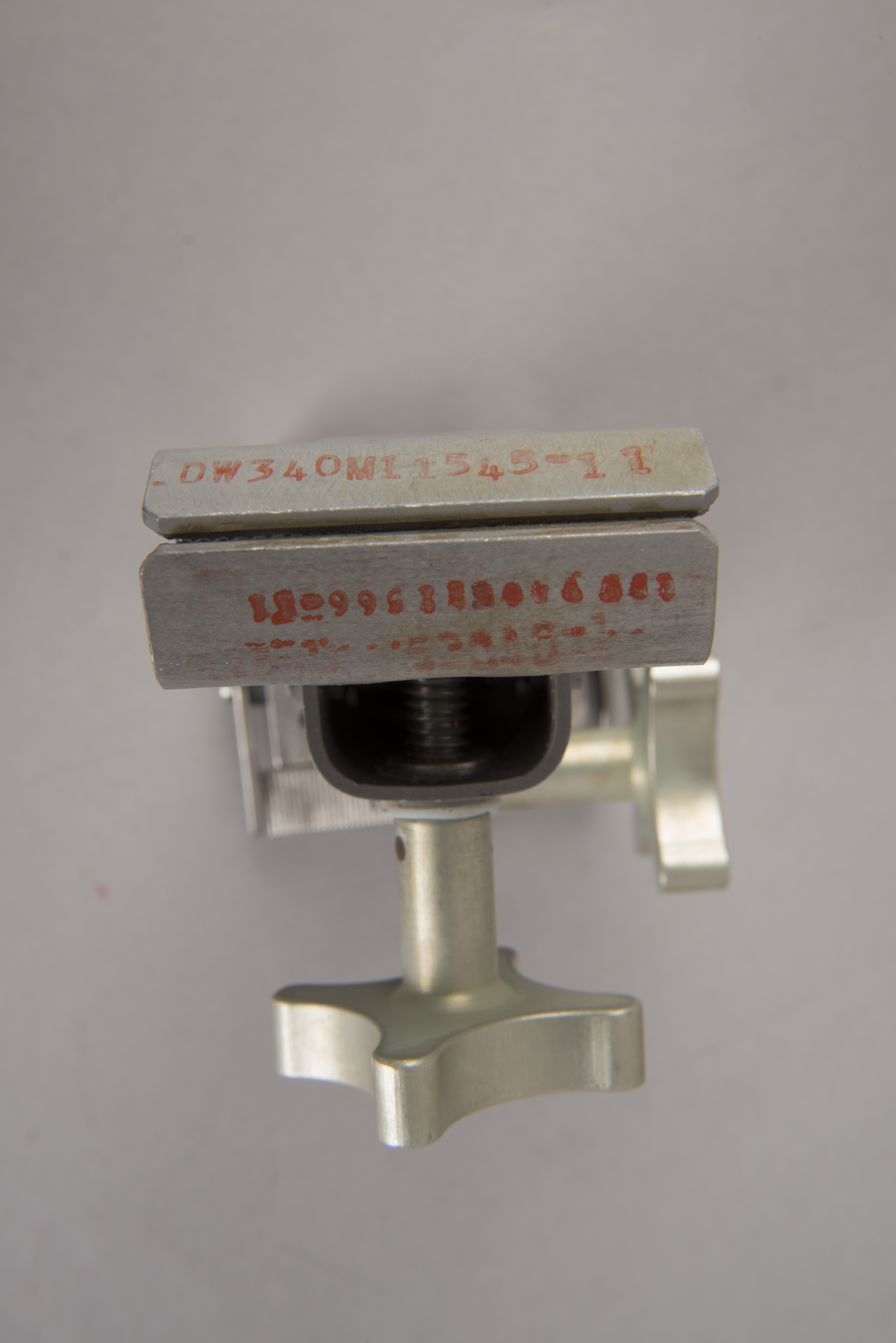 |
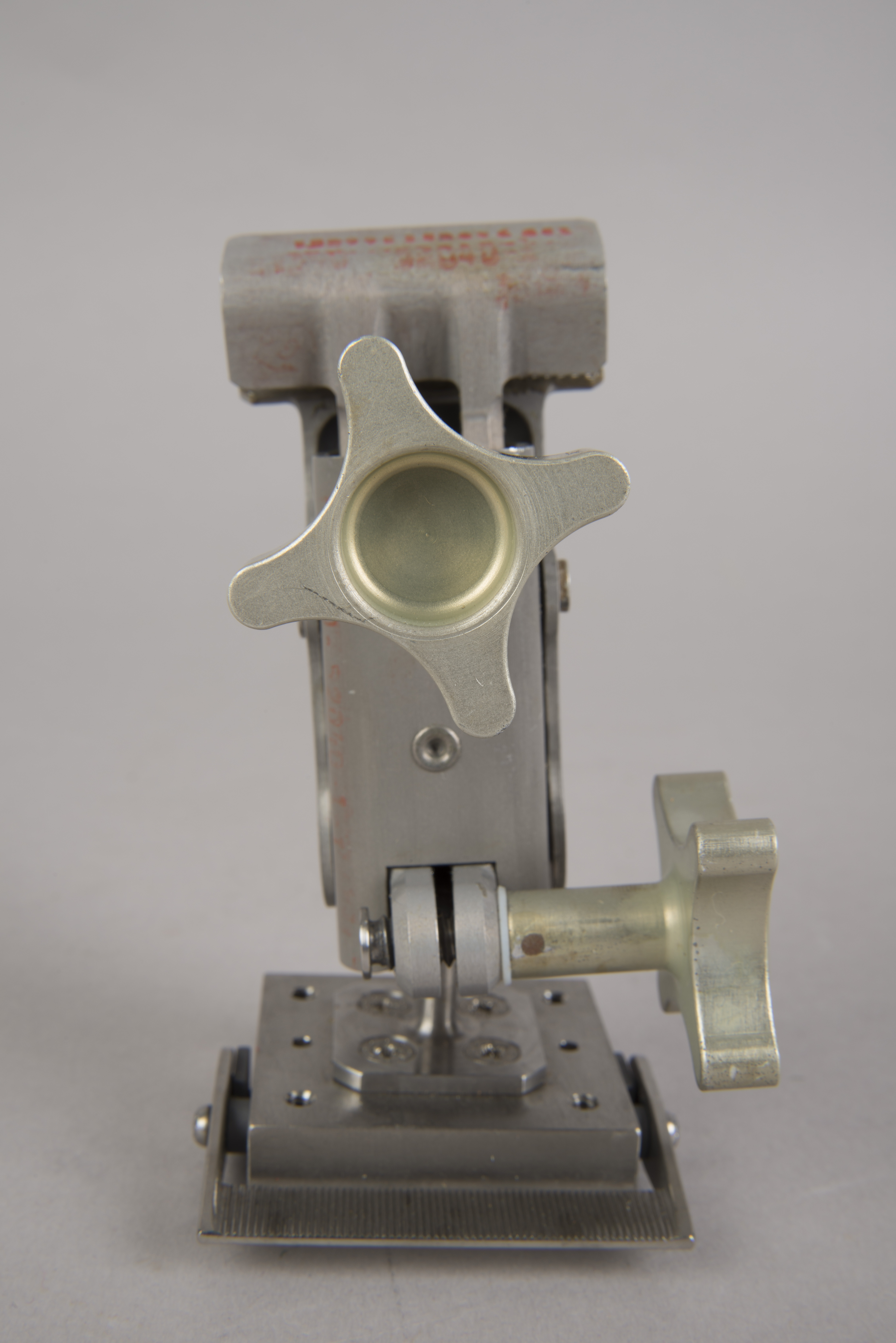
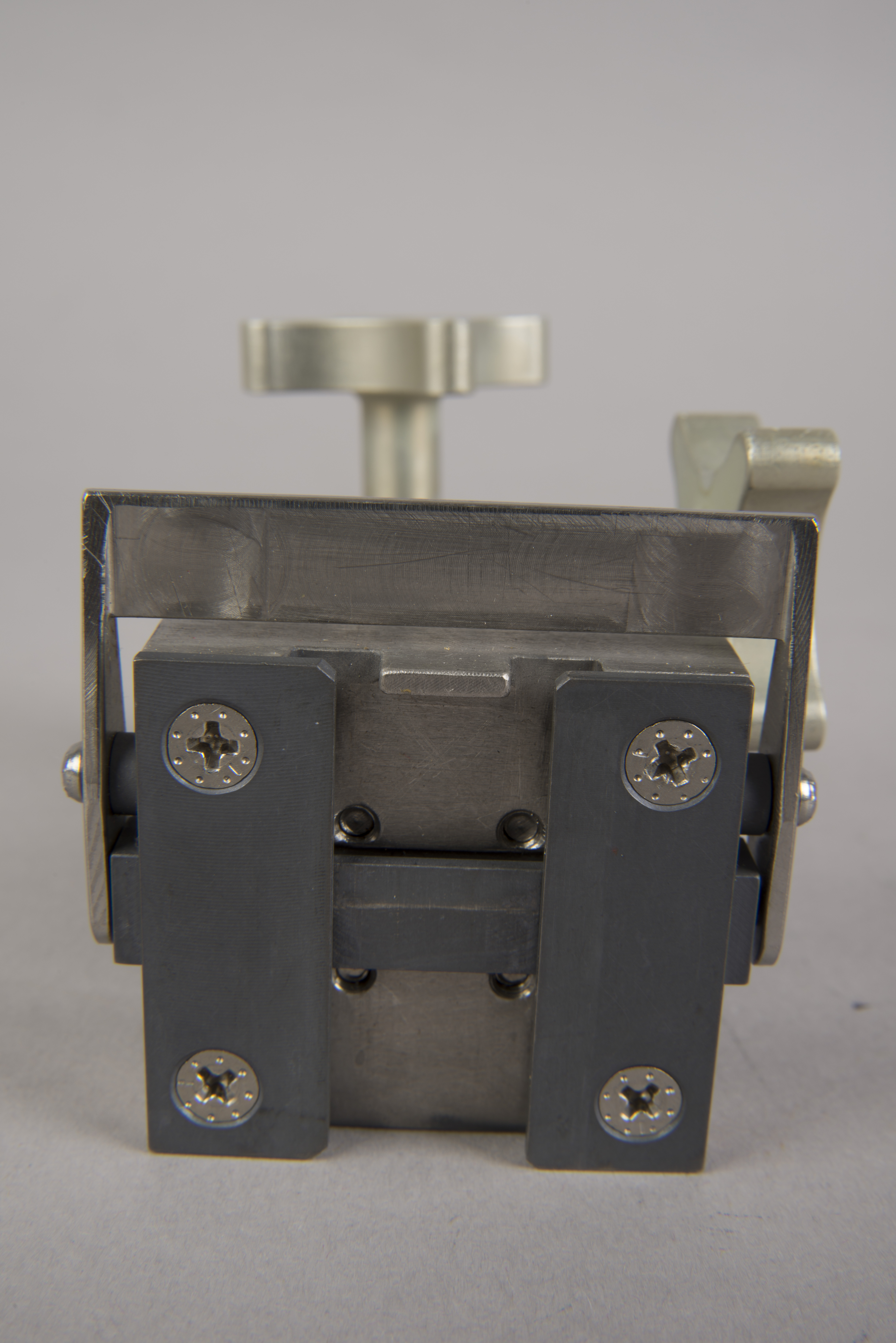
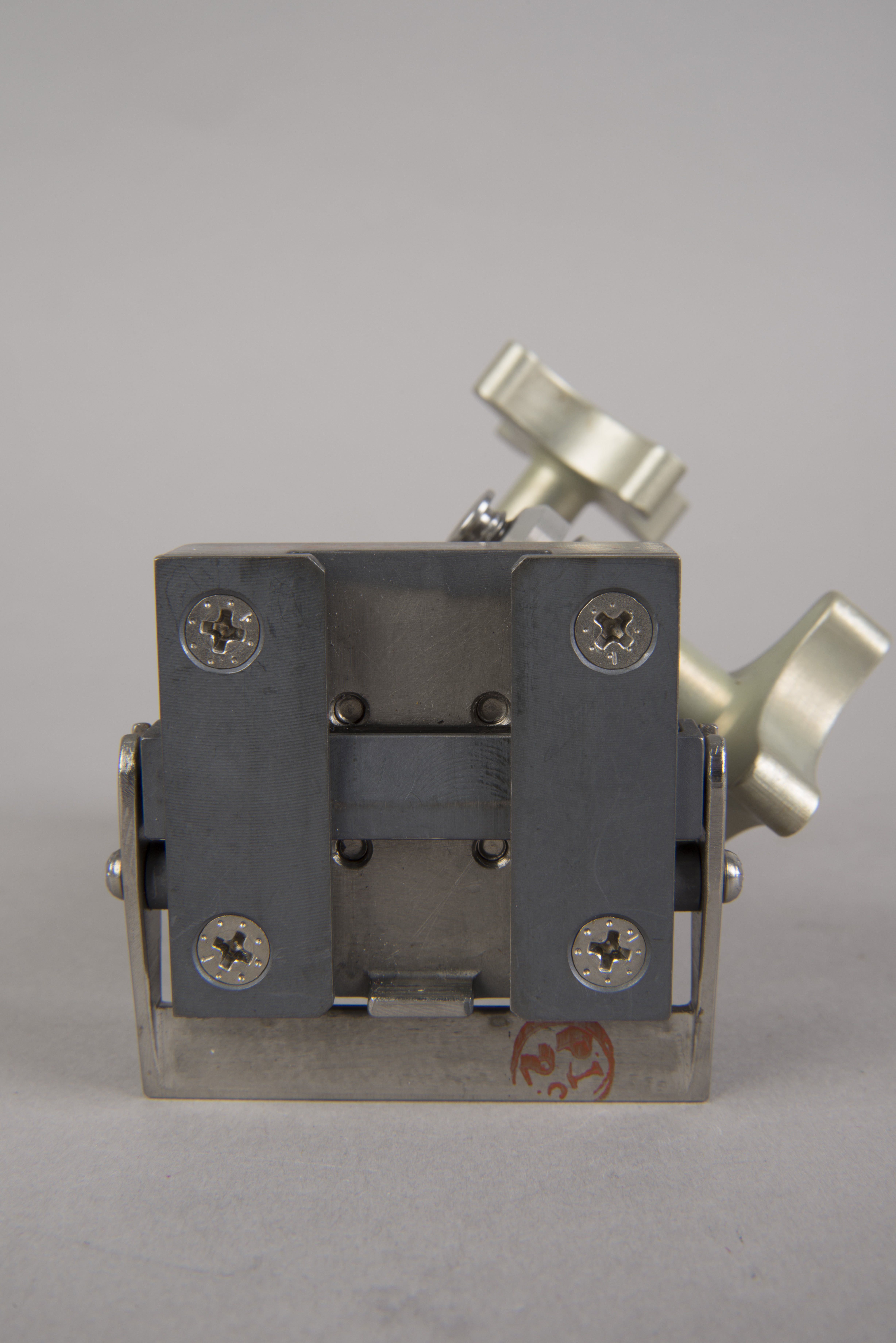
| In the images in the top
row and middle row right, the upper thumbscrew is used
to tighten or release the clamp jaws. Note the
grip pads on the inner surfaces of both clamp
jaws. The lower thumbscrew is used to loosen or
secure the mechanism that allows the relative
orientation of the clamp and bracket to be chosen. The
bracket at the bottom is used to mate the Assembly to
either the DAC or one of the Utility Lights. Operation
of the bracket is described in a section
below. (Click on the images for larger versions) |
Utility Clamp LDW-340M11545-11 / Bracket
LD-340-53051-3 / Inspection Stamp 738
NASM Conservation Photographs
 |
 |
 |
 |
 |
 |
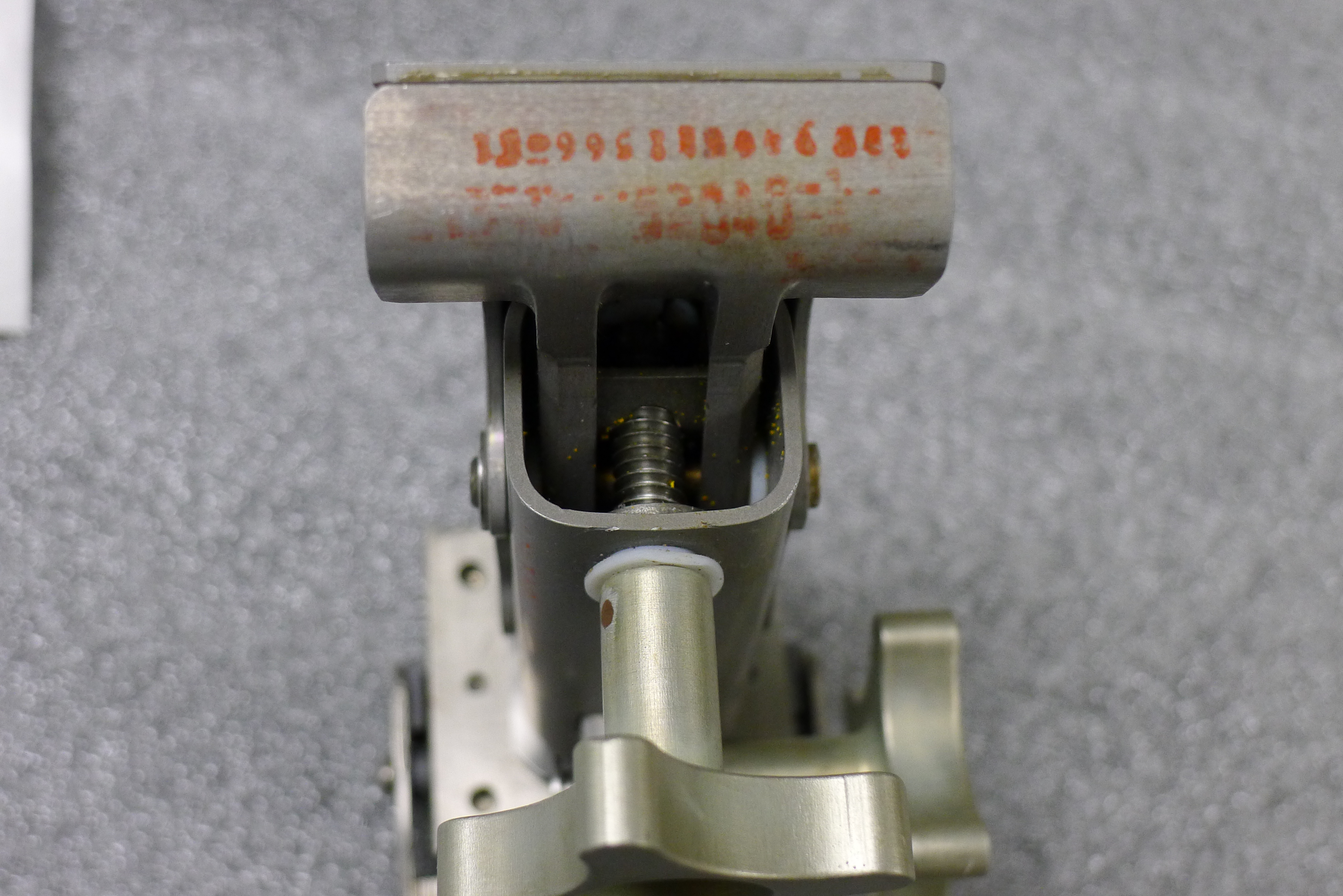
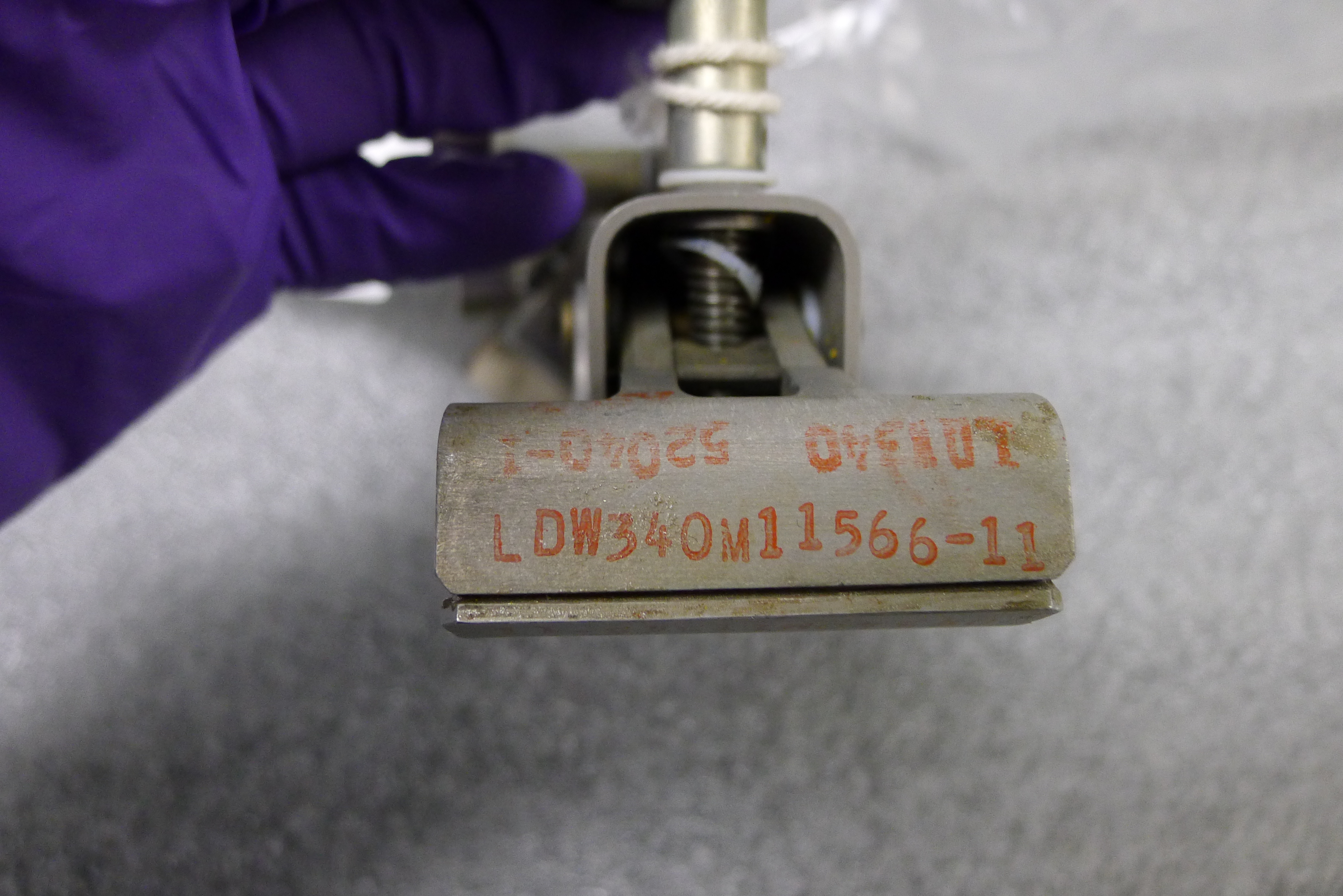
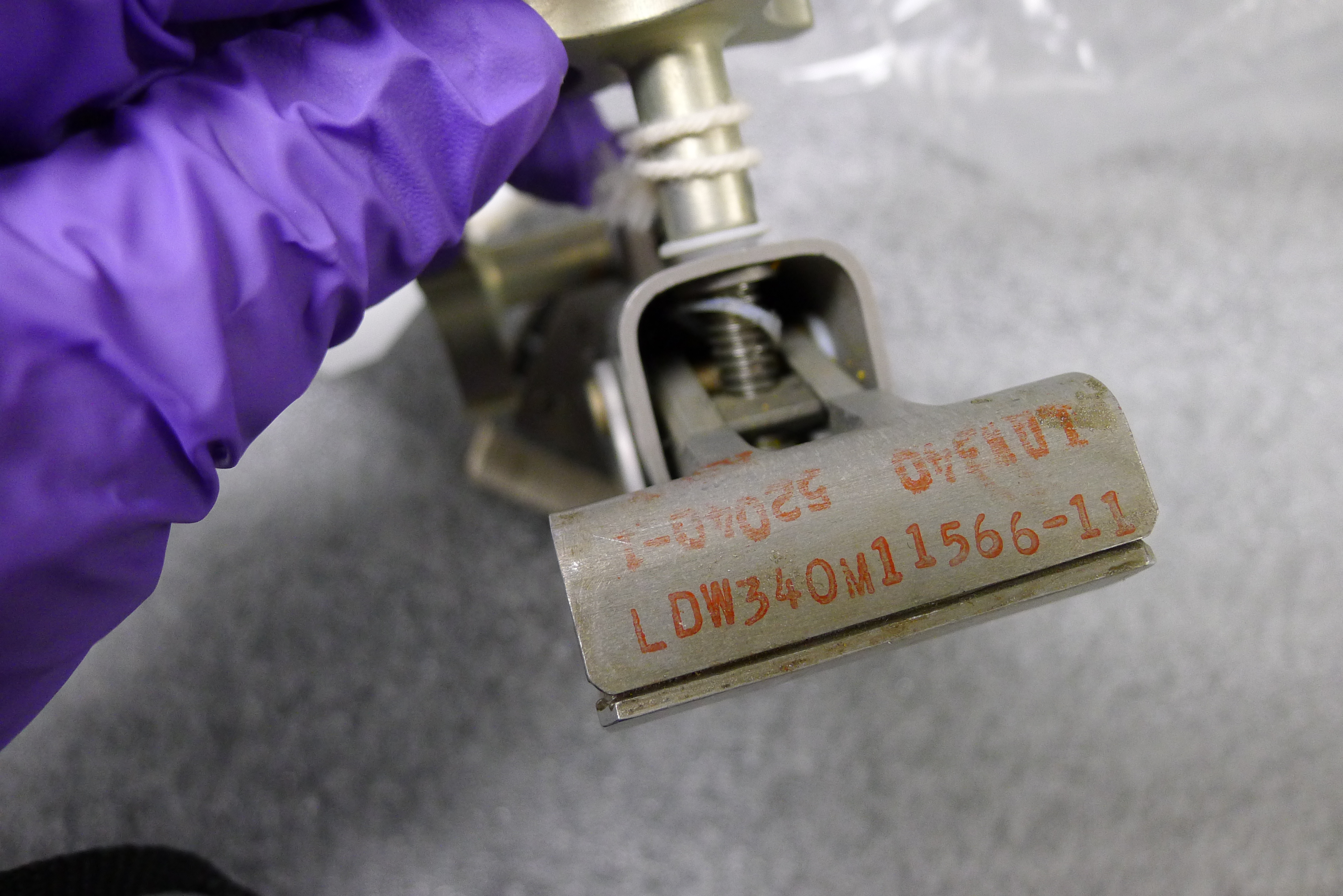
| Utility Bracket Assembly
with Inspection stamp '738'. A comparison between
the LDW340
stamp on this bracket, on the
one with inspection stamp 651, and a detail from AS11-36-5397
indicate that '738' is the bracket Buzz attached to the
crash bar for filming the descent and landing, primarily
because the LDW340 portion of '738' is next to the
bracket, was well inked, and was firmly pressed. In
contrast, the stamp on '651' is relatively faint and
inverted, putting the LDW340 portion farthest from the
bracket. (Click on the images for larger versions.) |
Return to
Apollo 11 Lunar Surface Journal
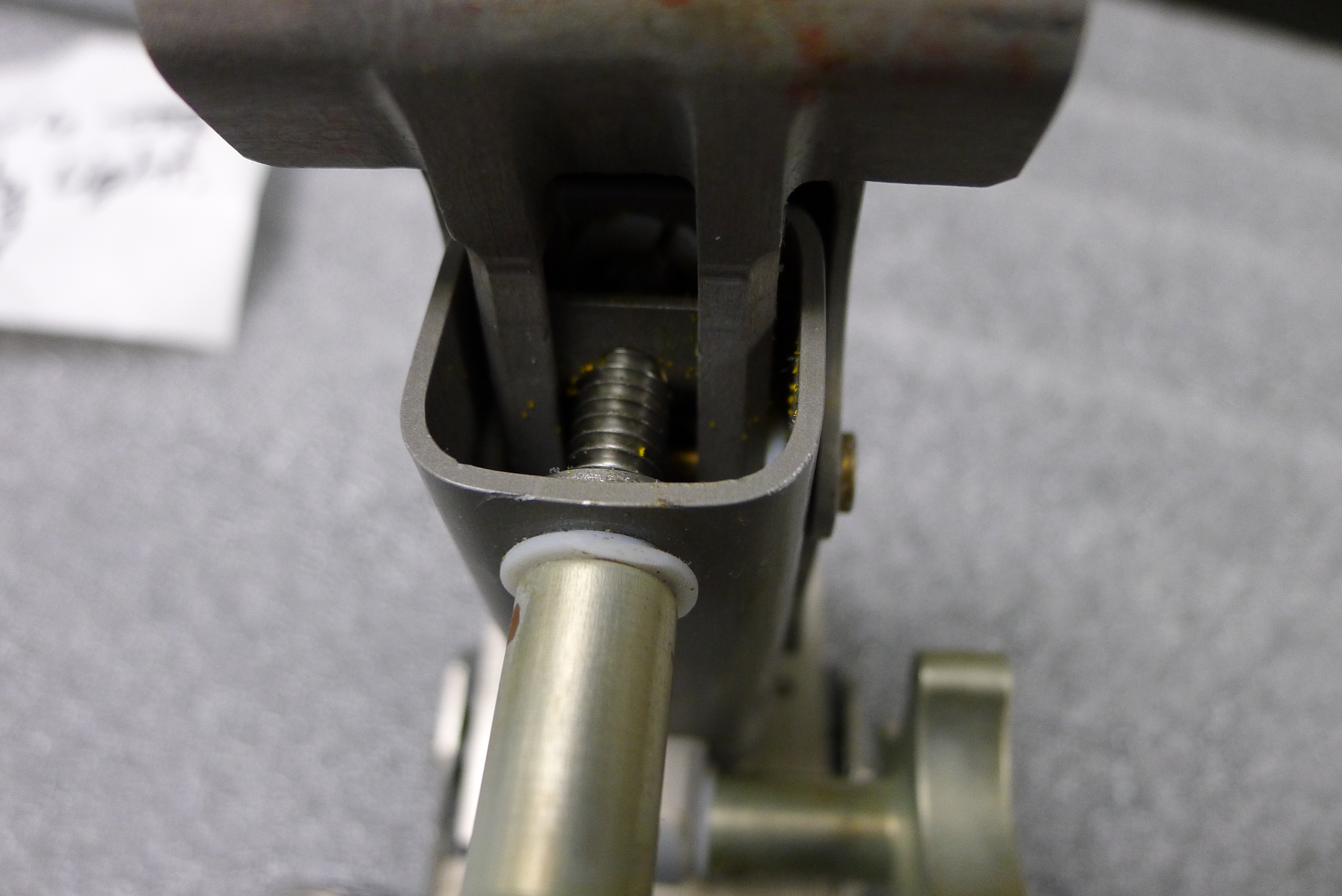
Yellow Paint Particles on the Utility Clamps
| In training photos, the Utility Clamps are often seen attached to the Alignment Optical Telescope Guard (AOT). The guard is painted yellow and, during close examination of the Apollo 11 Bracket Assemblies, Lisa Young at the National Air and Space Museum Conservation Unit noted what are probably particles of yellow paint in the well of the clamp body of both Utility Bracket Assemblies. Lisa writes "Most of the paint residue I saw was sort of spread throughout the entire screw mechanism and seemed to be loose, i.e. not all of it was adhered to the screw threads." |
NASM Conservation Photographs
 |
 |
 |
 |
| The top two images are
details showing numerous yellow paint particles in the
well of the clamp with inspection stamp
'651'. The bottom two images show two clearly
visible yellow paint particles in the well of the clamp
with inspection stamp '738'. Note the differences in the
red markings on each clamp and the presence of a teflon
washer resting diagonally across the tightening screw in
the bottom two images. (Click on the images
for larger versions.) |
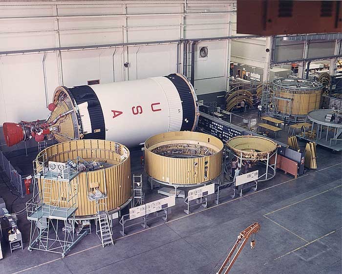
| Fred Karst, Director of Service Engineering
at Gulfstream Aerospace (a corporate descendant of
Grumman, the company that manufactured the Lunar Modules),
provides the following information about Zinc Chromate Primer,
which is very likely to be the coating on the AOT Guard: "For the LM, they would need corrosion protection as the vehicle would be in storage waiting for its flight. In Florida with its a very humid and salt laden air environment, protection would even be needed in a clean room. In aerospace, the vehicle is typically manufactured up to the primer coat. It is that primer coat that would be that yellow color, as that is the natural color of the chromates." Karst provided a photo of S-IVB stages being assembled, with yellow primer much in evidence. Fred adds "If the yellow material of the AOT guard is, in fact, the yellow epoxy paint that Grumman used - and for that matter we still do at Gulfstream, with our Grumman heritage - it tends to be brittle and will chip or flake off. The marks of yellow on the (snap)hook really do look like primer marks." The particles of yellow paint were probably scratched off the AOT guard when the clamps were either fastened to or removed from the AOT guard. The paint particles currently in the wells may not have been scraped off the guard during the mission but, rather, during Crew Compartment Fit and Function sessions done prior to the mission. See a discussion by Jack Schmitt. The following image is an enlarged detail from a photo taken during the Apollo 15 LM close-out at the Cape a day or two before launch. Similar photos from Apollos 12, 16, and 17 show scratches on each of the AOT guards. |
| Detail from an Apollo
15 LM close-out photo showing damage to the
yellow paint on the AOT guard done by the clamps. |
Return to
Apollo 11 Lunar Surface Journal
Utility Bracket Operation
Lotzmann Photos
(The item shown is not in the Smithsonian collection nor among the Armstrong material)
 |
 |
 |
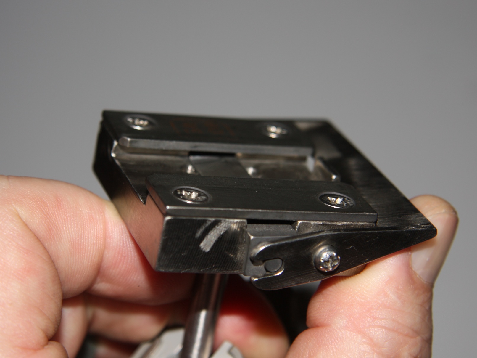 |
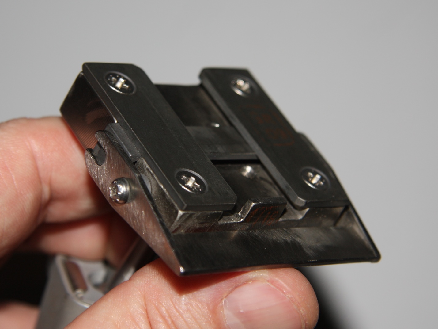
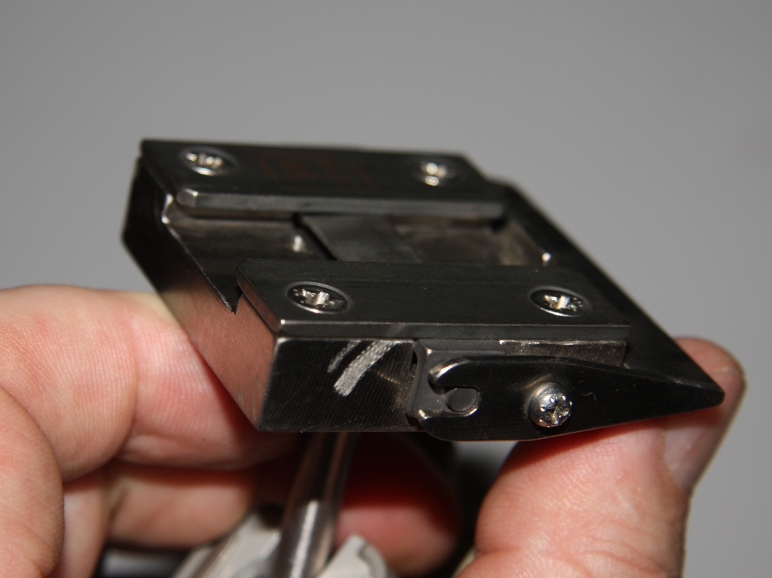
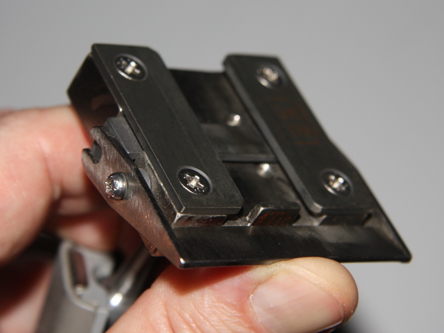
| (Top Left) Front view of
the bottom of the utility bracket in its engaged
position; (Top Right) Side view of the bracket in its
engaged configuration; (Bottom row) Upward pressure on
the front of the rocker arm, pulls a locking bar
downward out of the way so that the male fitting on a utility light
or the DAC can be inserted from left to right as seen in
the side views. (Click on the images for larger
versions.) |
Return to
Apollo 11 Lunar Surface Journal
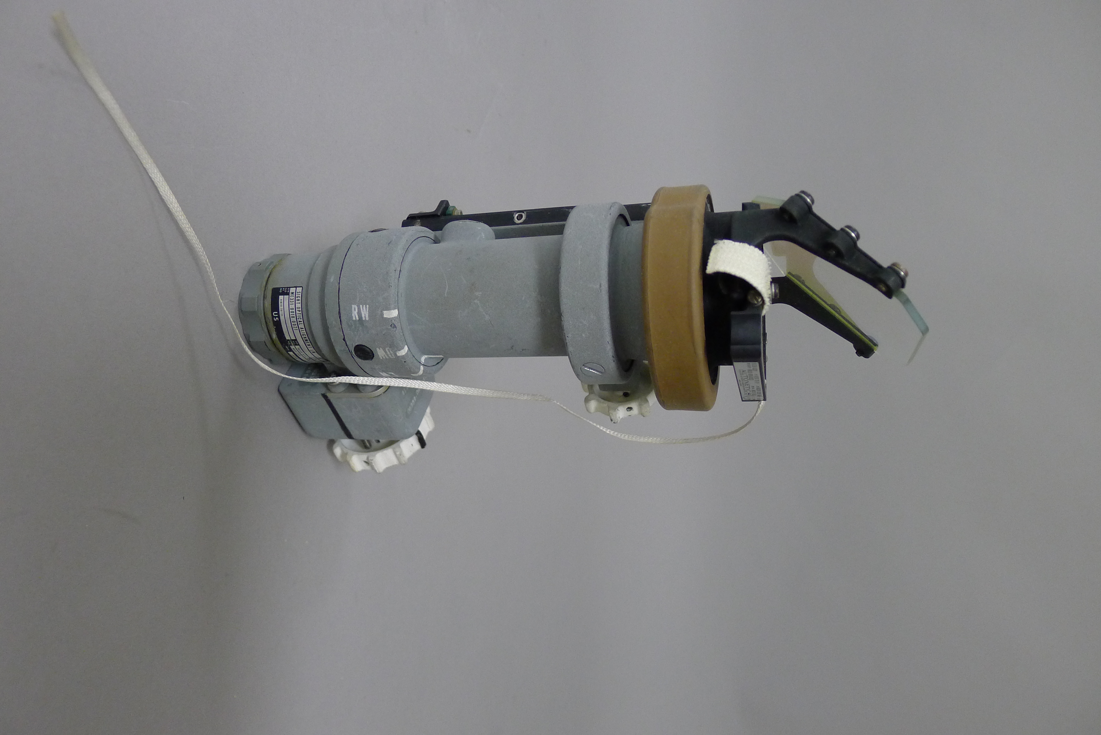
Crewman Optical Alignment Sight (COAS)
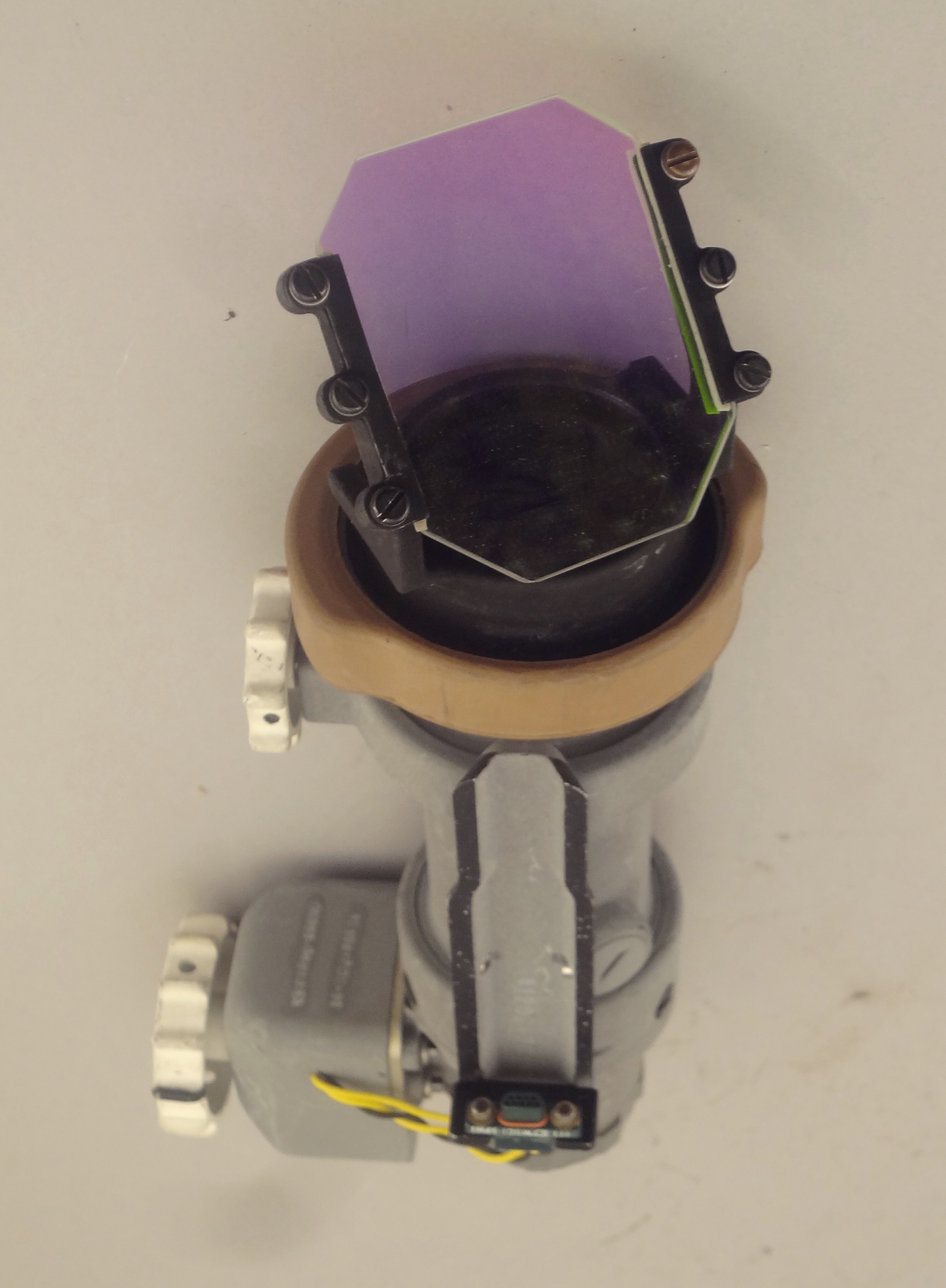
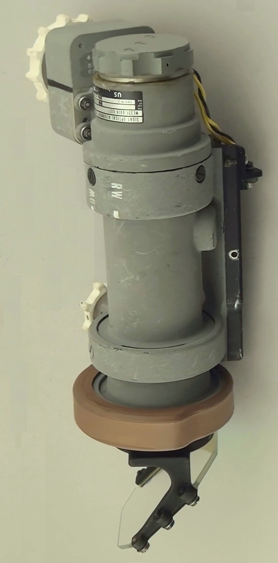
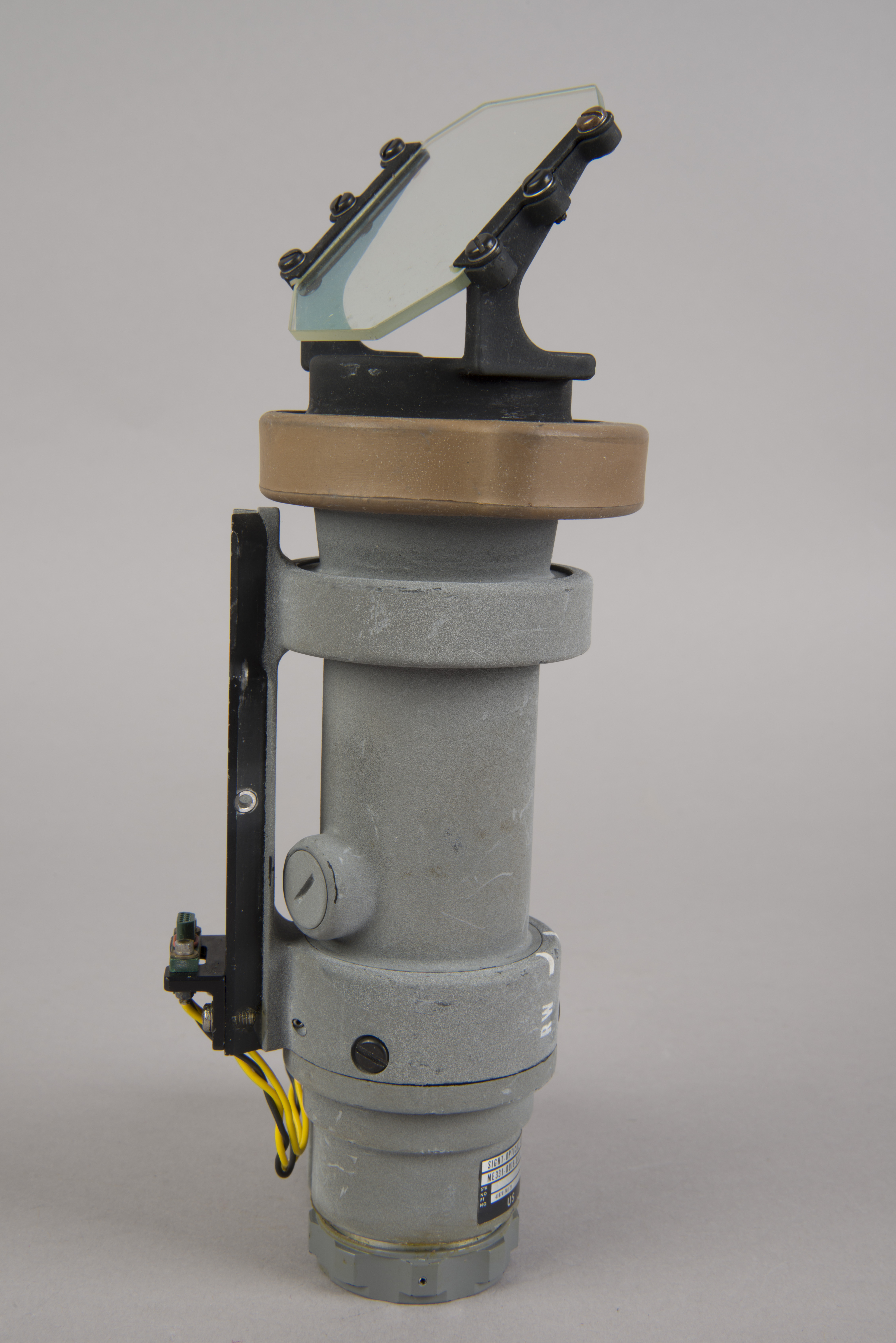
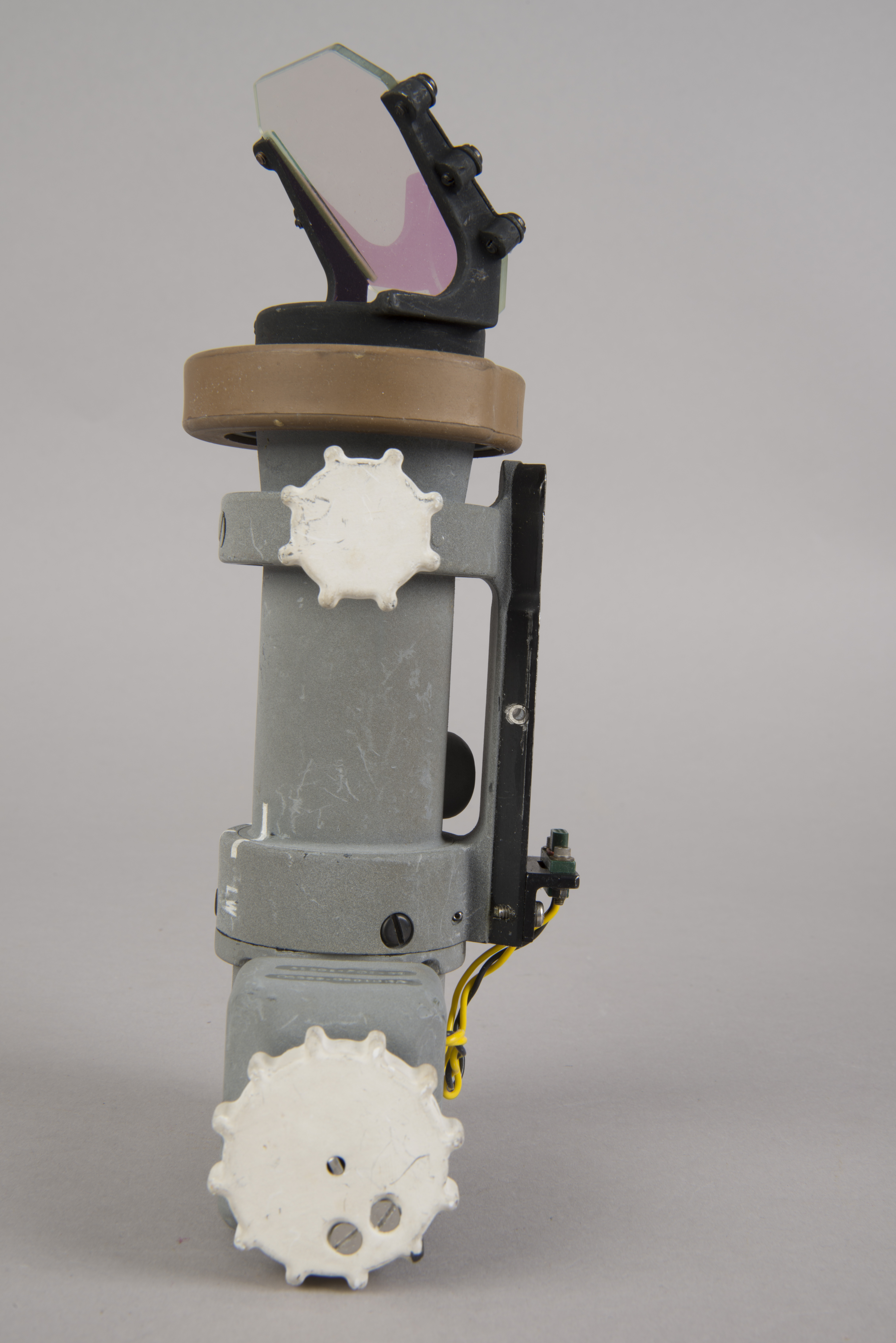
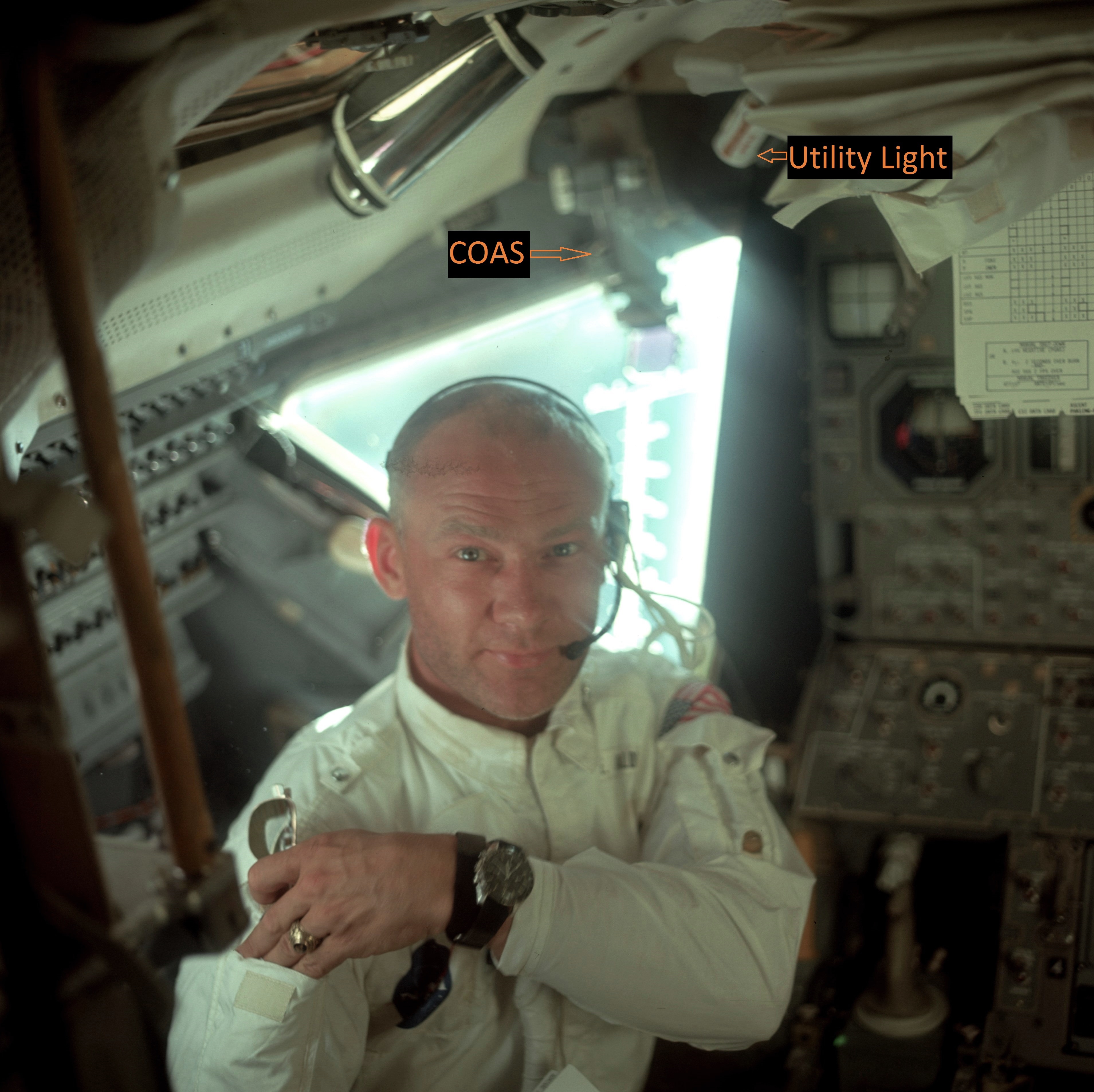
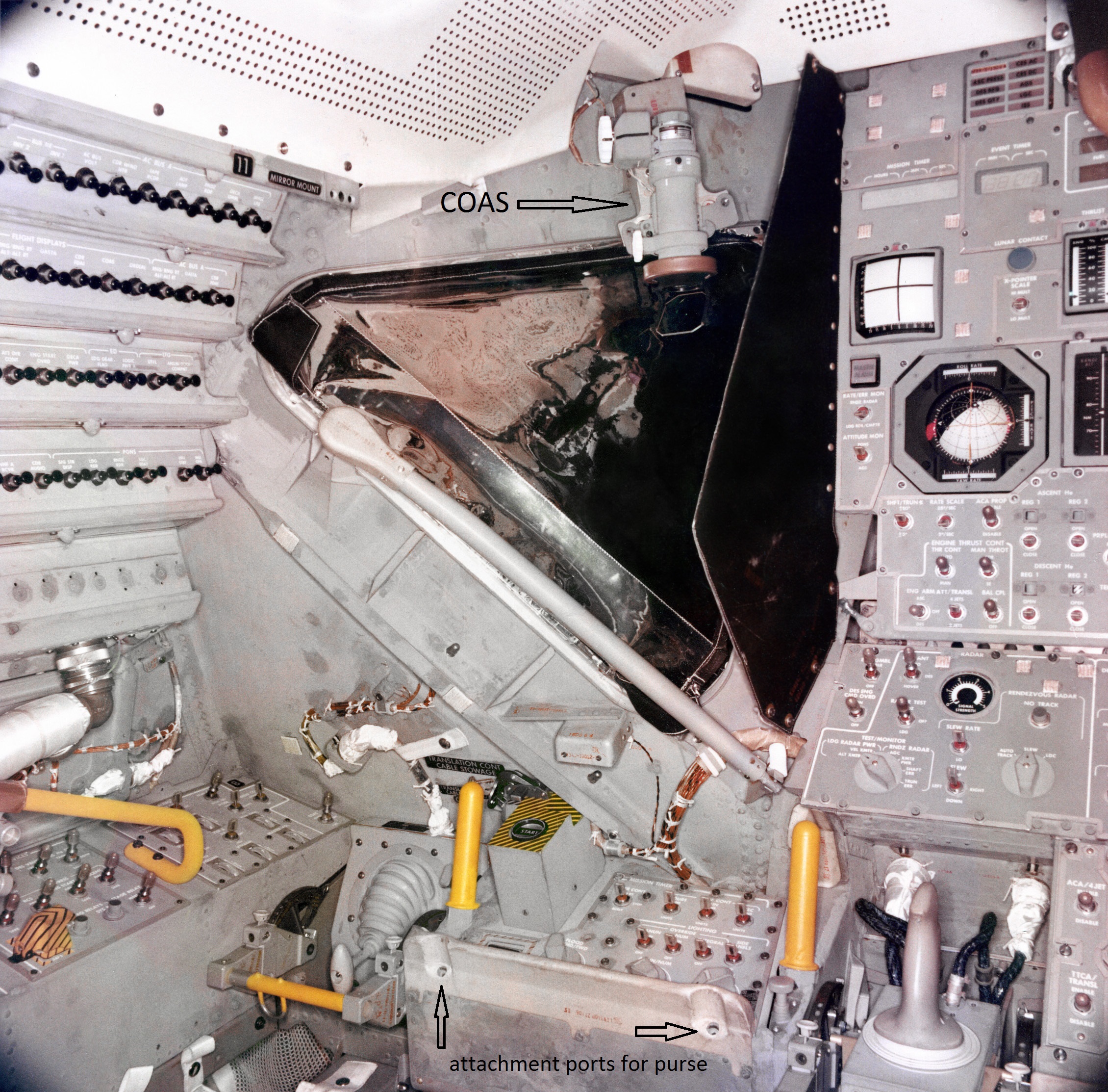
| Crewman Optical Alignment
Sight (COAS) which was installed above Armstrong's
window. Adjustment wheels on the side away from the
camera. Lotzmann photo. (Click on the image for a larger version) |
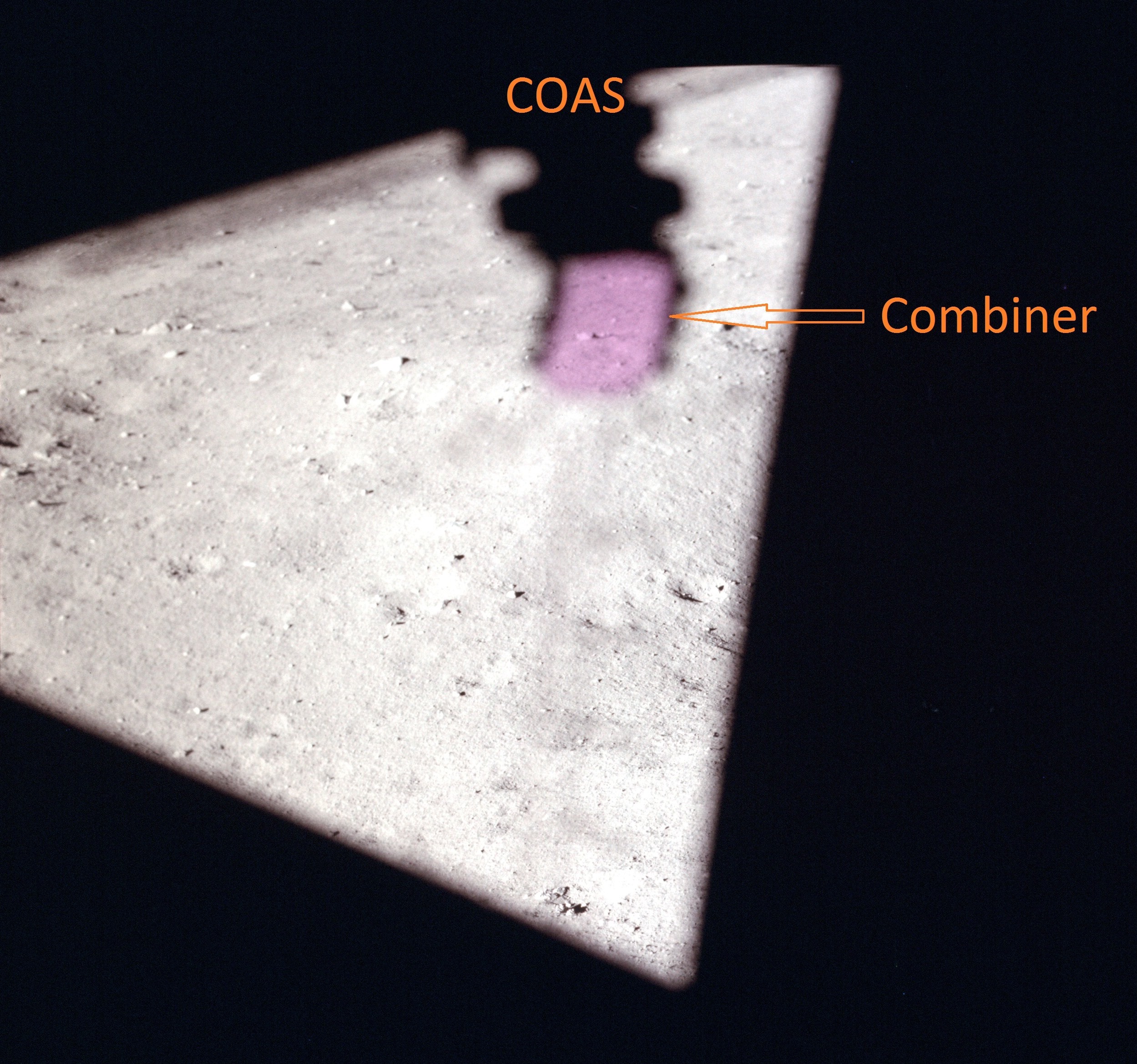
| Detail from AS11-36-5398, showing the COAS mounted above Armstrong's window. Photo taken by Armstrong during the initial LM imspection during the trip out from Earth. Note that the combiner end is down. (Click on the image for a larger version.) The COAS can also be seen in a labeled version of AS11-37-5527, and in AS11-37-5529, both of which were taken after the EVA. See, also, a photo taken on 18 March 1969, of a COAS mounted in the Neil's window the day before a run in the Altitude chamber; and a labeled version of AS11-36-5390. |
| From the Apollo
News Reference, pp. CPE10-11): The COAS provides the Commander with gross range cues and closing rate cues during the docking maneuver. The closing operation, from 150 feet to contact, is an ocular, kinesthetic (eye, hand) coordination that requires control with minimal use of fuel and time. The COAS provides the Commander with a fixed line-of-sight attitude reference image, which appears to be the same distance away as the target. The COAS is a collimating instrument. It weighs approximately 1.5 pounds, is 8 inches long, and operates from a 28-volt d-c power source. The COAS consists of a lamp with an intensity control, a reticle, a barrel-shaped housing and mounting track, and a combiner (the angled piece of glass) and power receptacle. The reticle has vertical and horizontal 10-degree gradations in a 10-degree segment of the circular combiner glass, on an elevation scale (right side) of -10 degrees to +31.5 degrees. The COAS is capped and secured to its mount above the left window (position No. 1). To use the COAS, it is moved from position No. 1 to its mount on the overhead docking window frame (position No. 2) and the panel switch is set from OFF to OVHD. The intensity control is turned clockwise until the reticle appears on the combiner glass; it is adjusted for required brightness. The docking target permits docking to be accomplished on a three-dimensional alignment basis. The target consists of an inner circle and a standoff cross of black with self-illuminating disks within an outer circumference of white. The target-base diameter is 17.68 inches. The standoff cross is centered 15 inches higher than the base and, as seen at the intercept, is parallel to the X-axis and perpendicular to the Y-axis and the Z-axis. |
| Page CPE-11 in the
Grumman Lunar Module News Reference. |
Lotzmann Photos
 |
 |
 |
 |
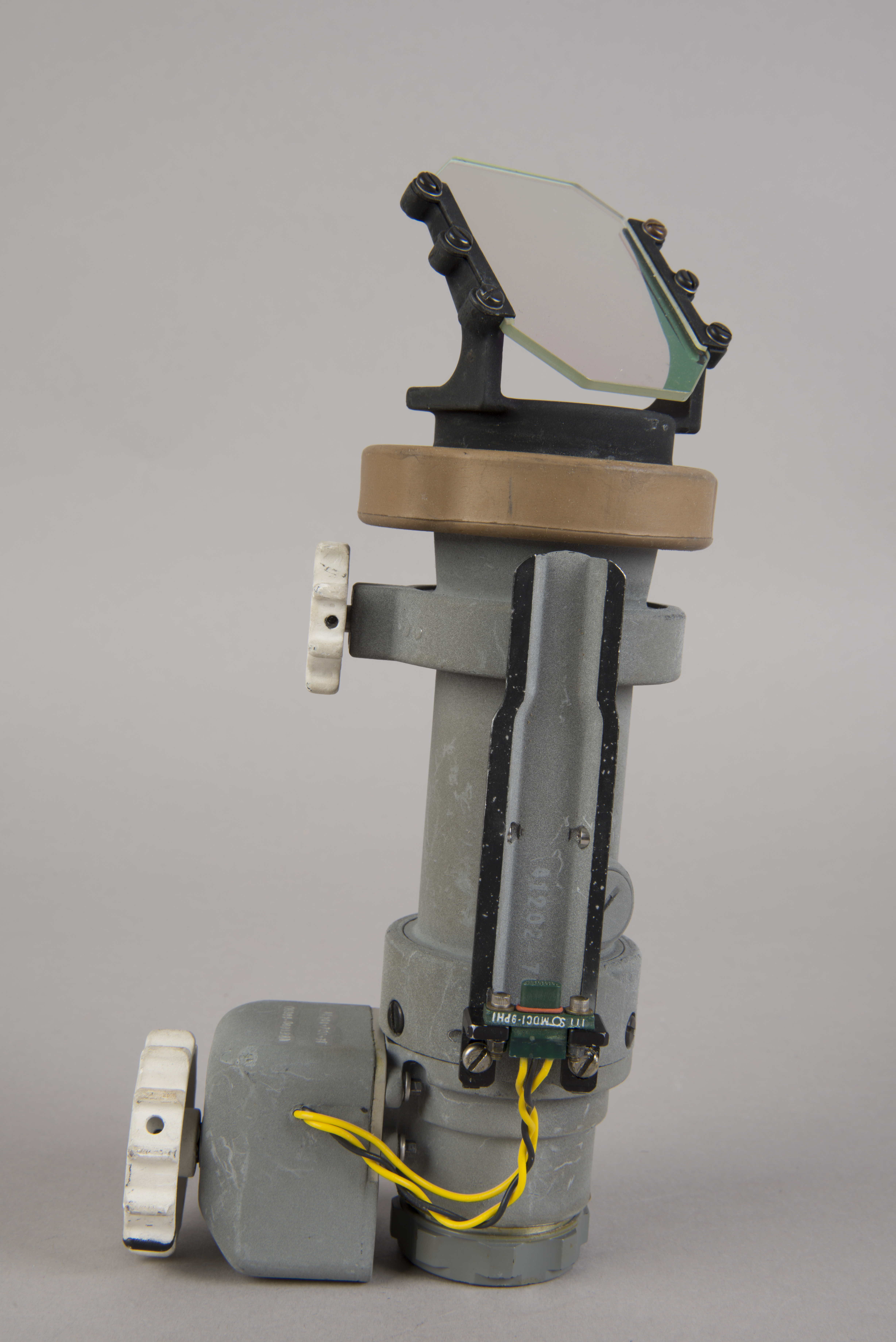
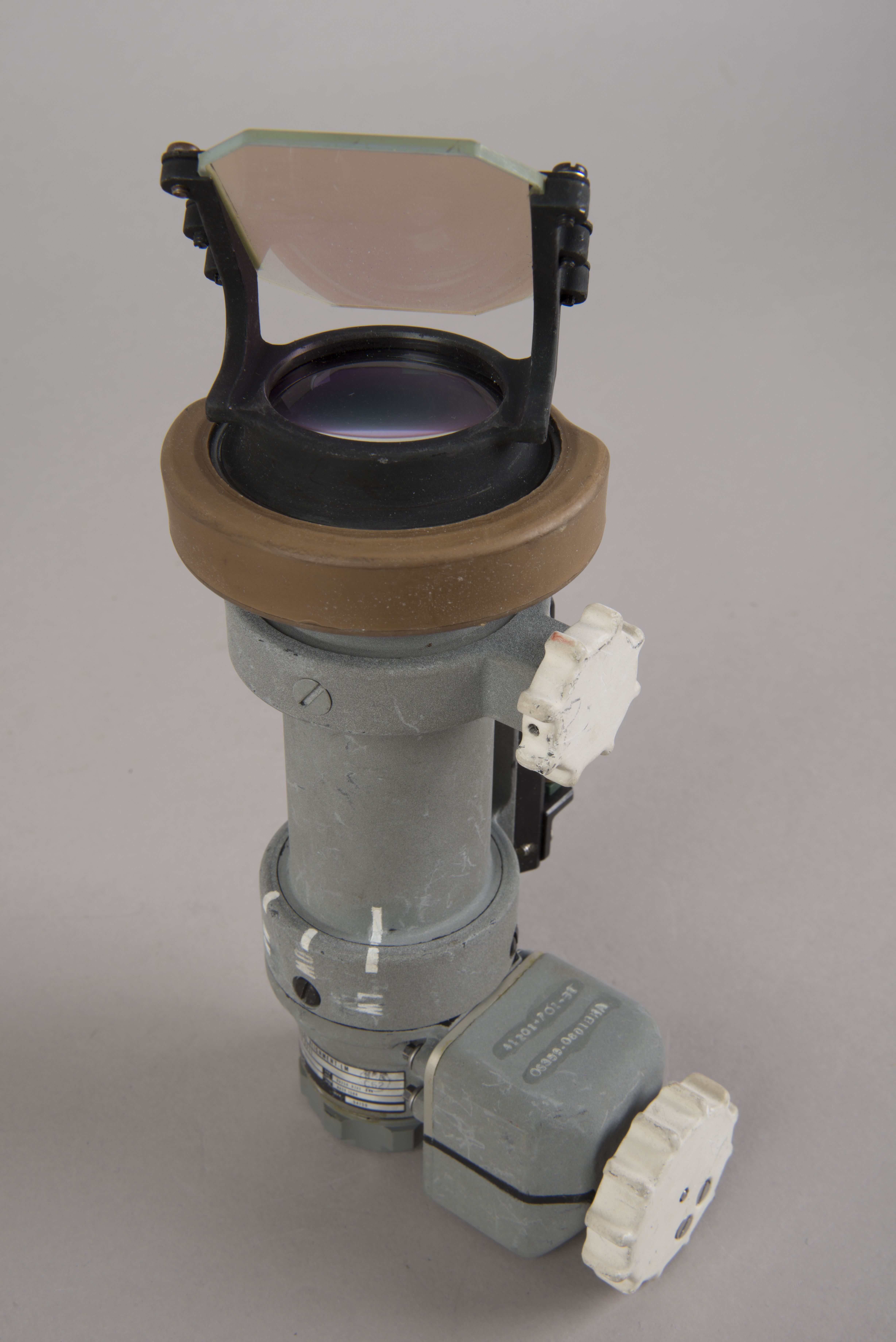
| Side view with adjustment
wheels toward camera. The combiner is on the left
and the light-source cap is on the right. Mounting track
facing upward. |
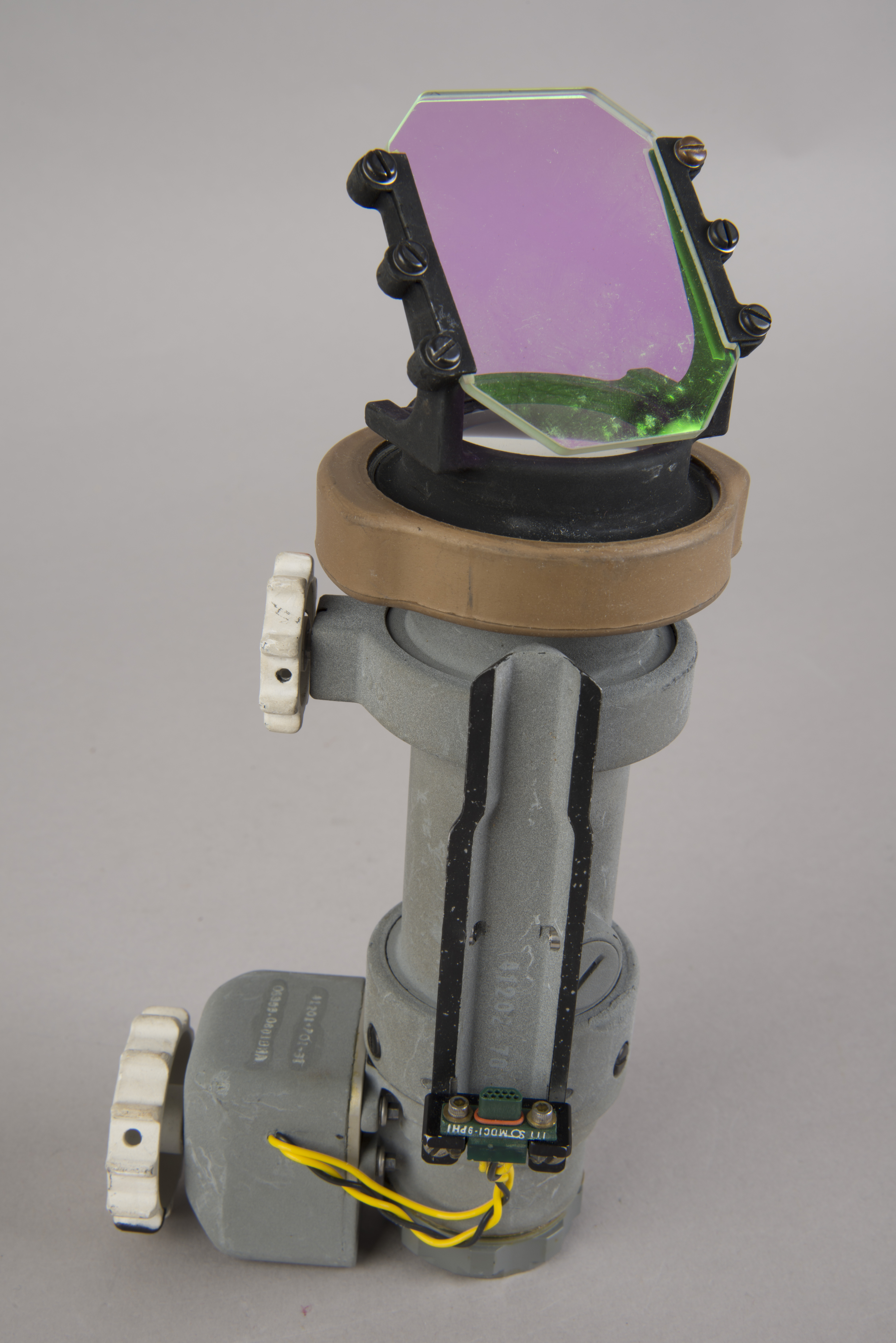
View along mounting track
with filter (combiner)-end closest to the camera.
Note that the black/yellow wires seem to connect with
electrical contacts at the far end of the bracket. |
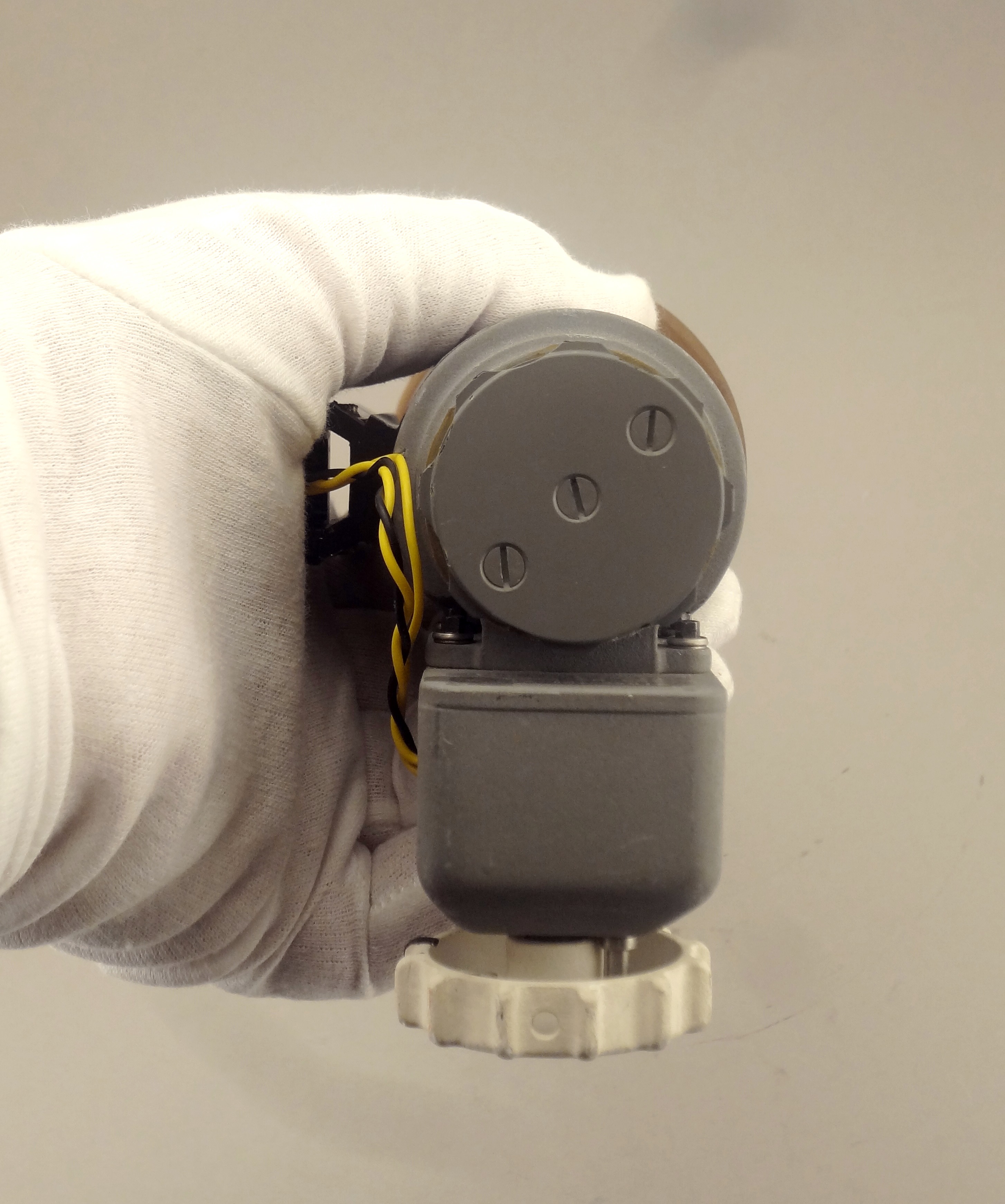
View of the light-source
cap. The box on the left may be a mechanism for
adjusting the light source intensity. |
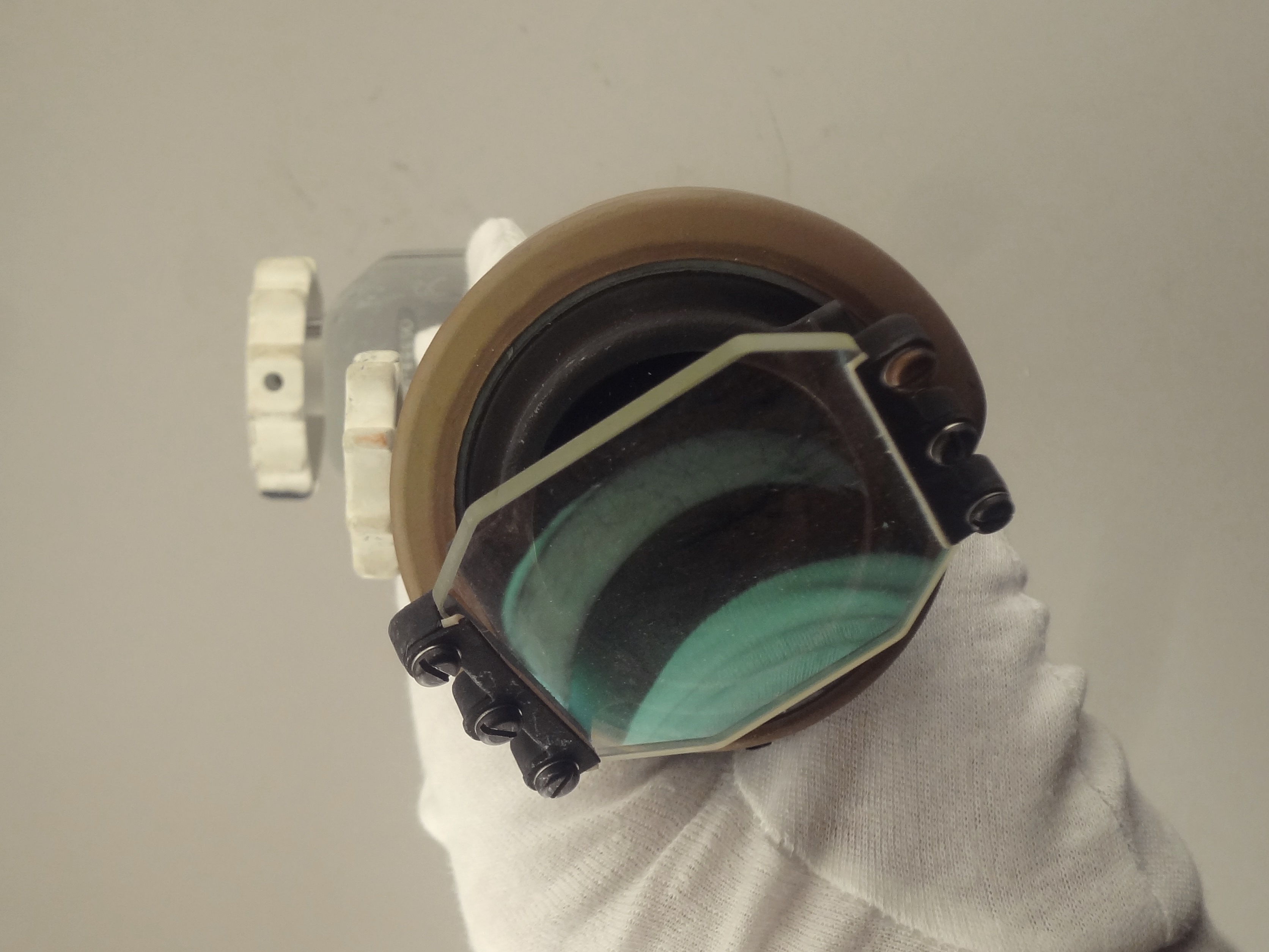
View through the
combiner. |
| The text from the LM News
Reference uses the words "Mounting track". The two
photos on the left indicate that electrical contact with
the dc power source is made at the top of the track
(farthest from the diagonally mounted combiner) and that
current flows through the yellow and black wires into
the adjacent, side-mounted box. (Click on the images for larger versions) |
 |
 |
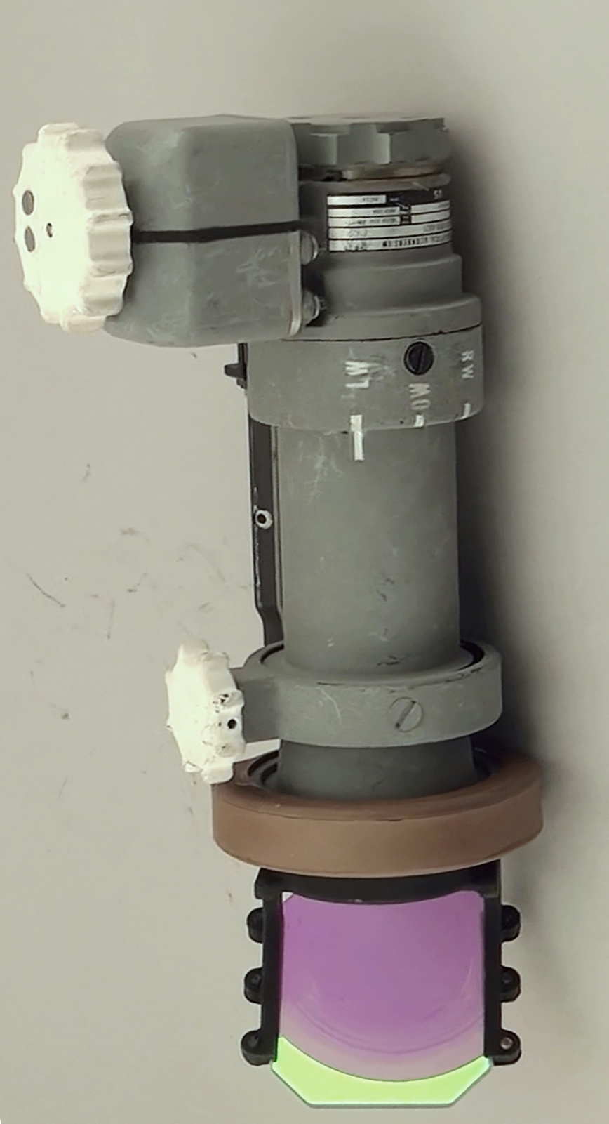
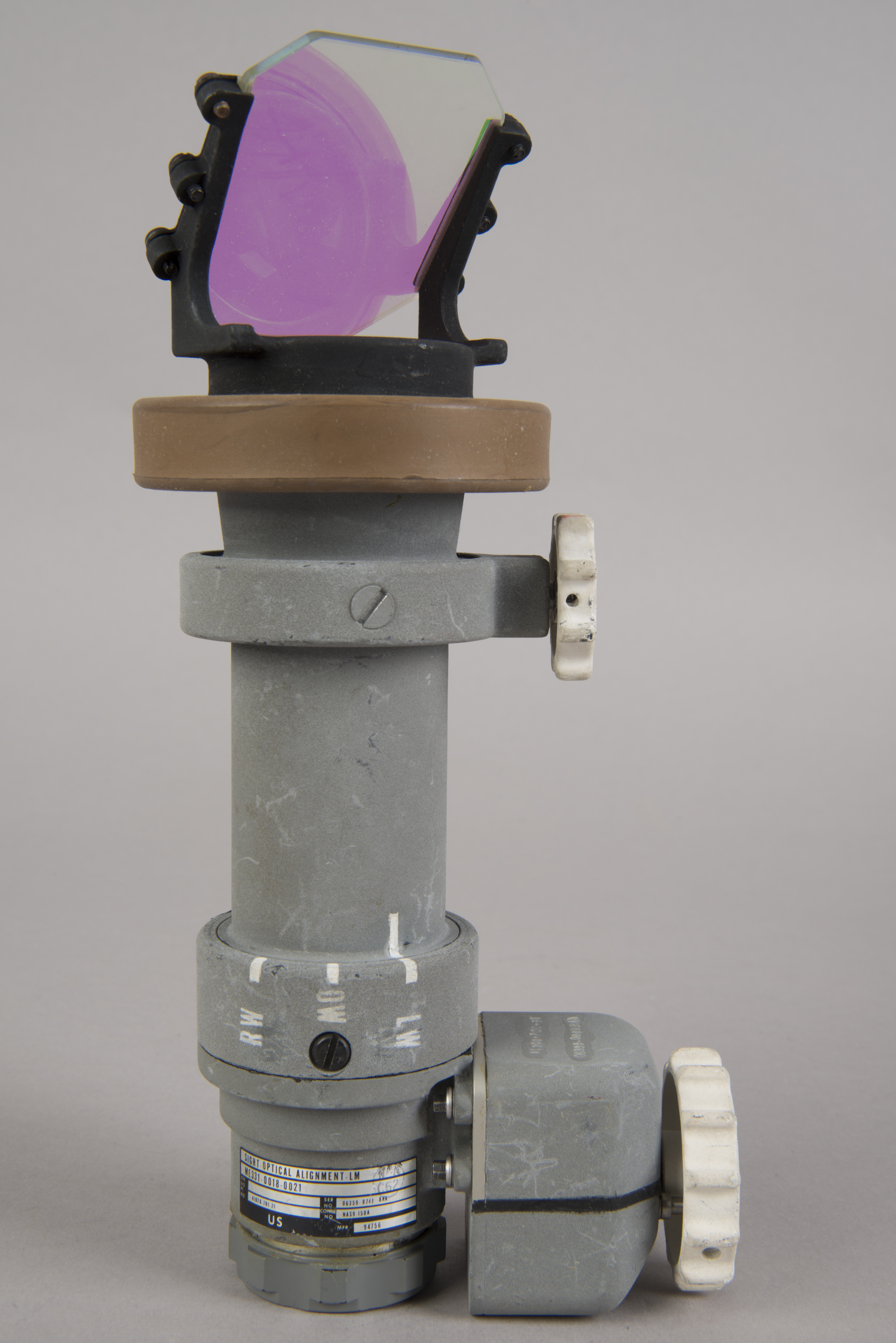
| The upper end of the
COAS could be rotated to any of three detents.
These detents put the reticle in orientations
suitable for the COAS being mounted in the CDR's
window (LW = Left Window), the Rendezvous window (OW
= Overhead Window), or the LMP's window (RW = Right
Window. Lotzmann high-definition video frames.
(Click on the images for larger versions.) |
NASM Conservation Photographs
 |
 |
 |
 |
 |
 |
Return to Collection Image
Return to Apollo 11 Lunar Surface Journal
COAS Filter with Casing
NASM Conservation Photographs
 |
 |
 |
 |
 |
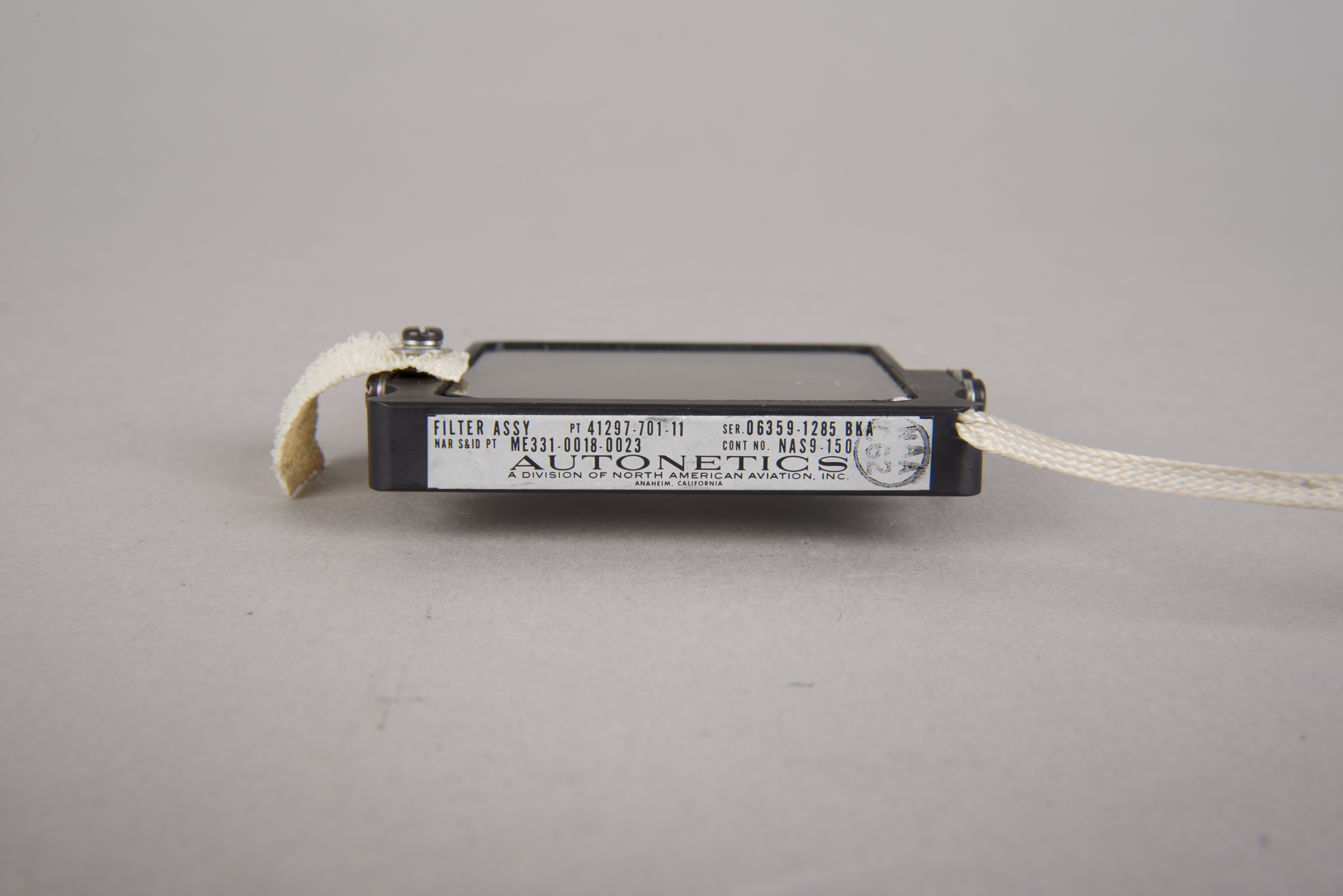 |
| COAS filter. Note the
spring clips, one on each side, in the righthand images
in the top two rows. (Click on the images for larger versions.) |
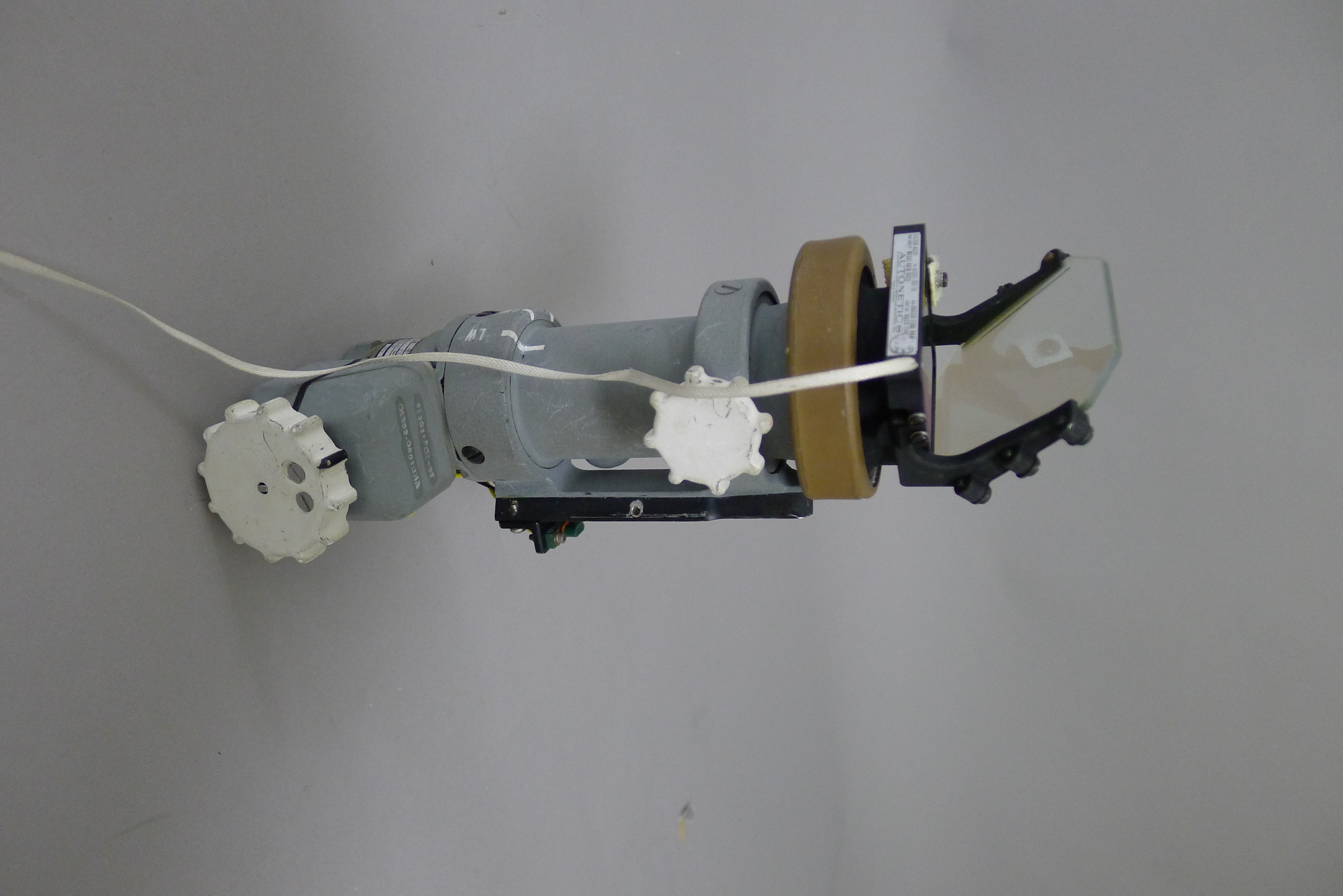
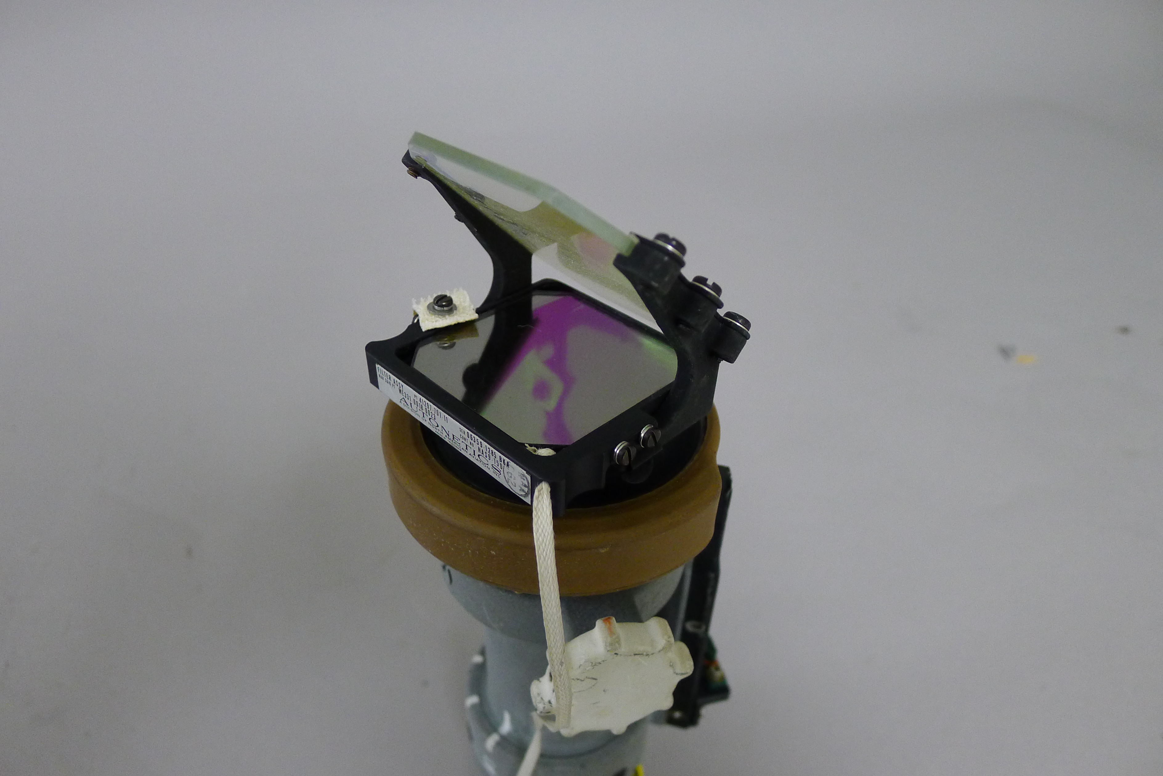
COAS with Filter Installed
NASM Conservation Photographs
 |
 |
 |
 |
| Apollo 11 COAS with
filter installed. (Click on the images for larger versions) |
Return to Collection Image
Return to Apollo 11 Lunar Surface Journal
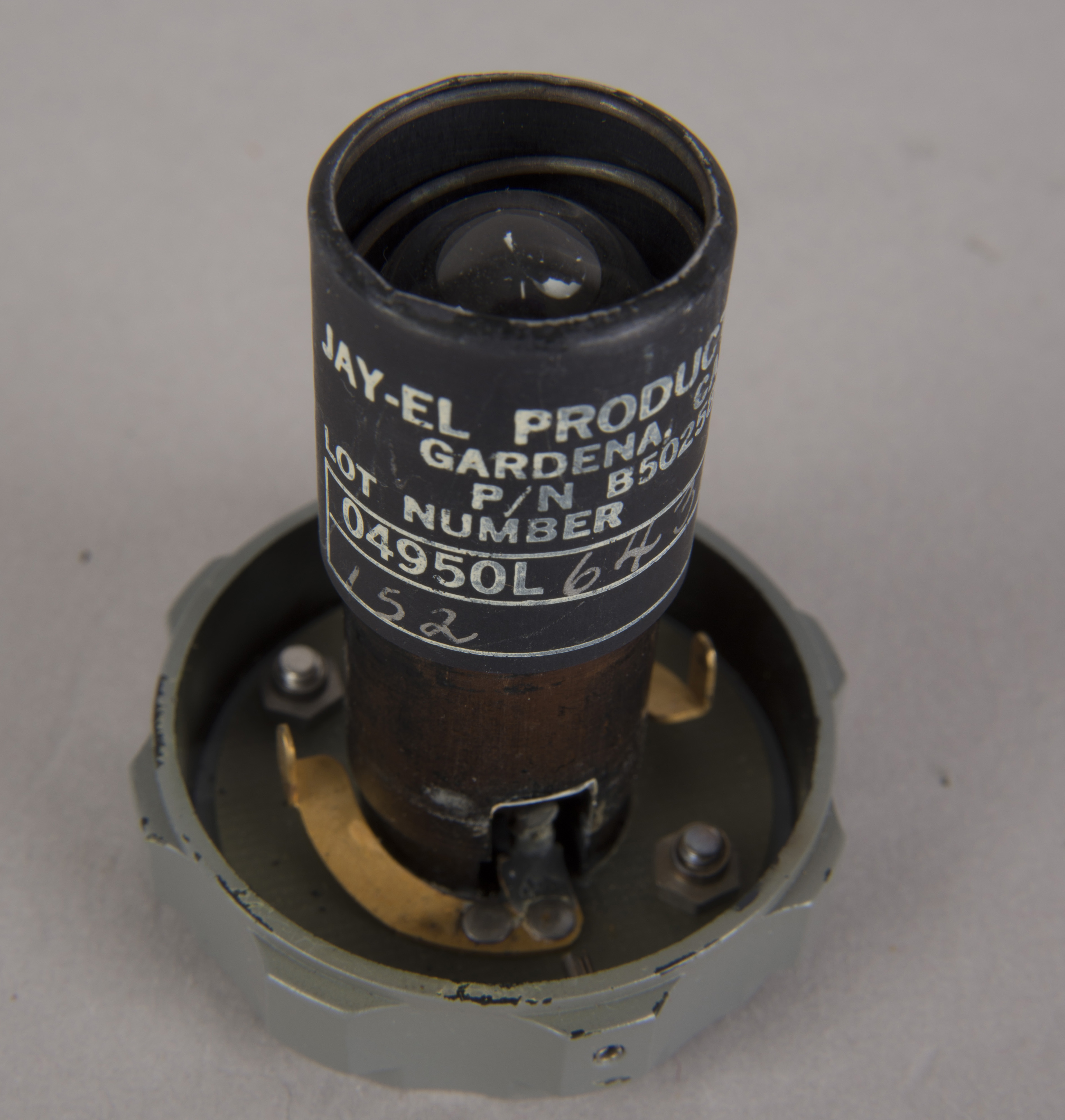
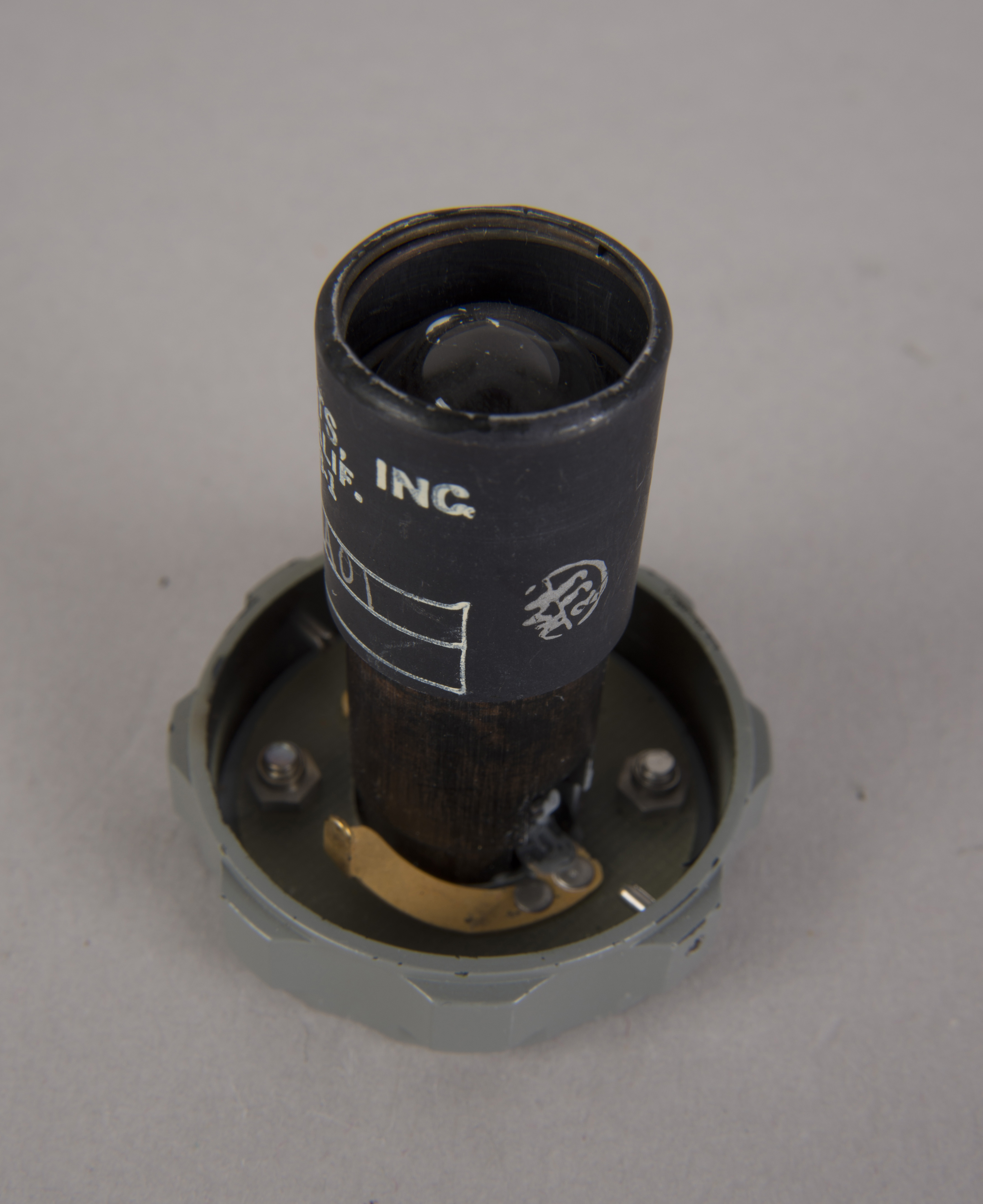
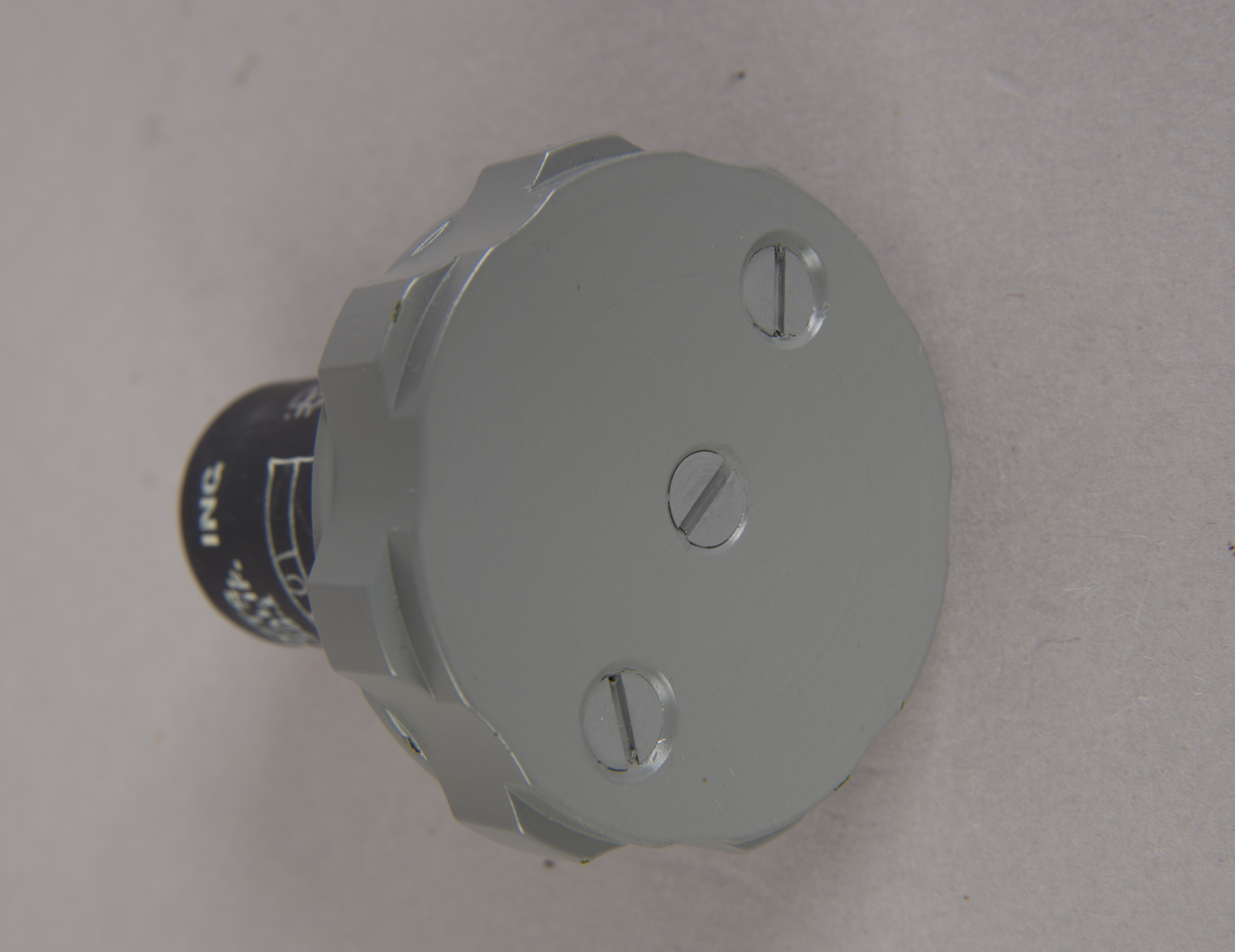
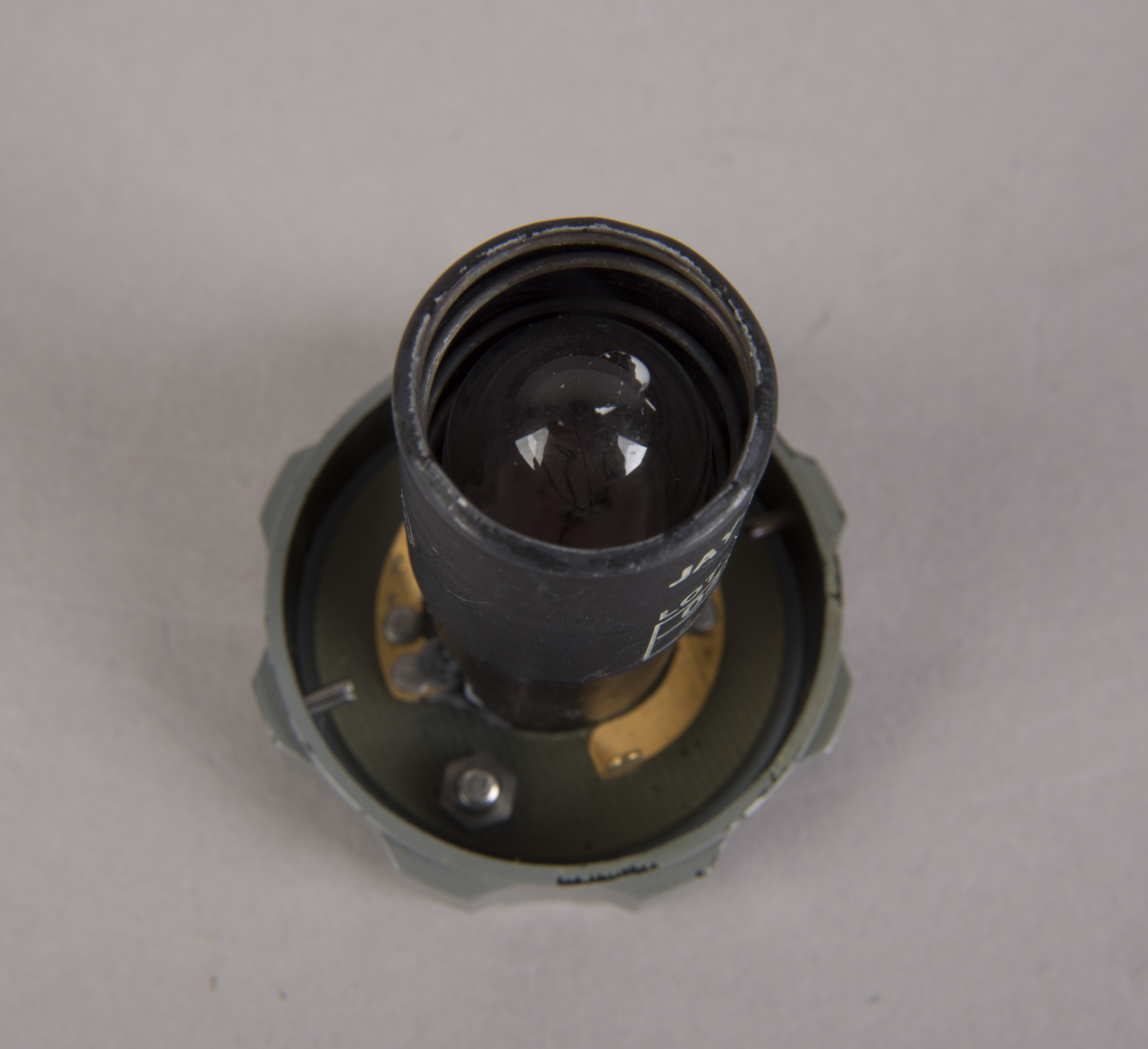
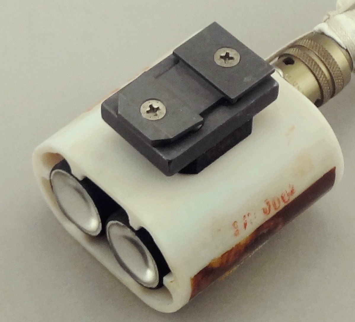
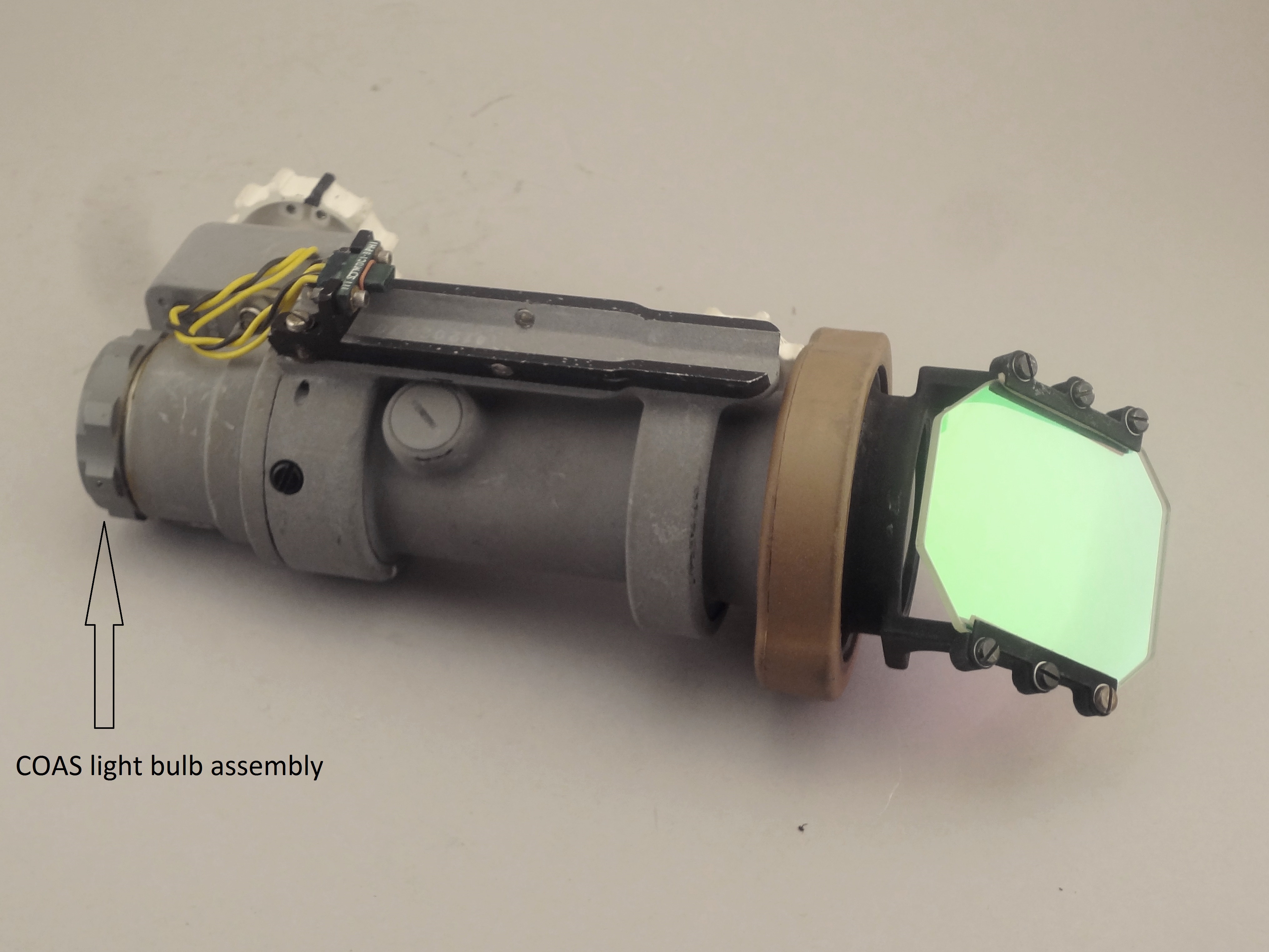
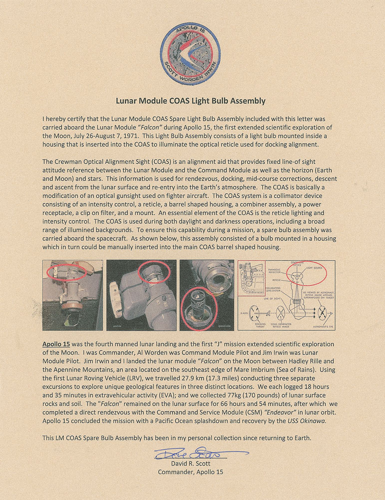
Crewman Optical Alignment Sight (COAS) Spare Light Bulb Assembly
| COAS light bulb assembly (spare). An identical assembly was on the end of the COAS closest to the cabin overhead. This spare was stowed in the Right-Hand-Side Stowage Compartment (RHSSC) next to Buzz's flight station. Images of the Apollo 12 and Apollo 15 flown items are available from external sources. See, also, a description from Dave Scott of the flown Apollo 15 item. Lotzmann photograph. (Click on the image for a larger version.) |
NASM Conservation Photographs
 |
 |
 |
 |
 |
 |
| (Click on the images for
larger versions.) |
Return to
Apollo 11 Lunar Surface Journal
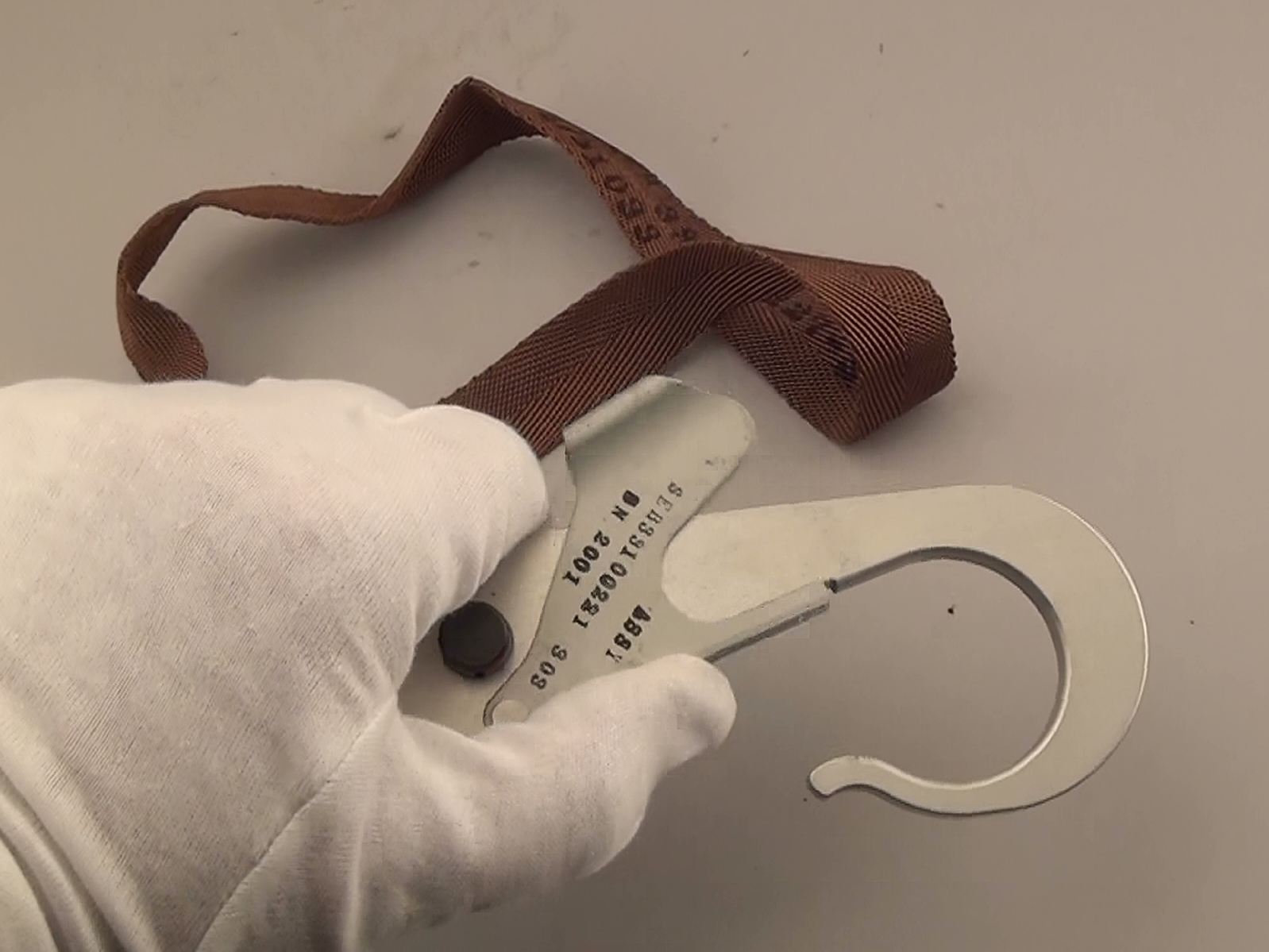
Waist Tether (EVA)
NASM Conservation Photograph
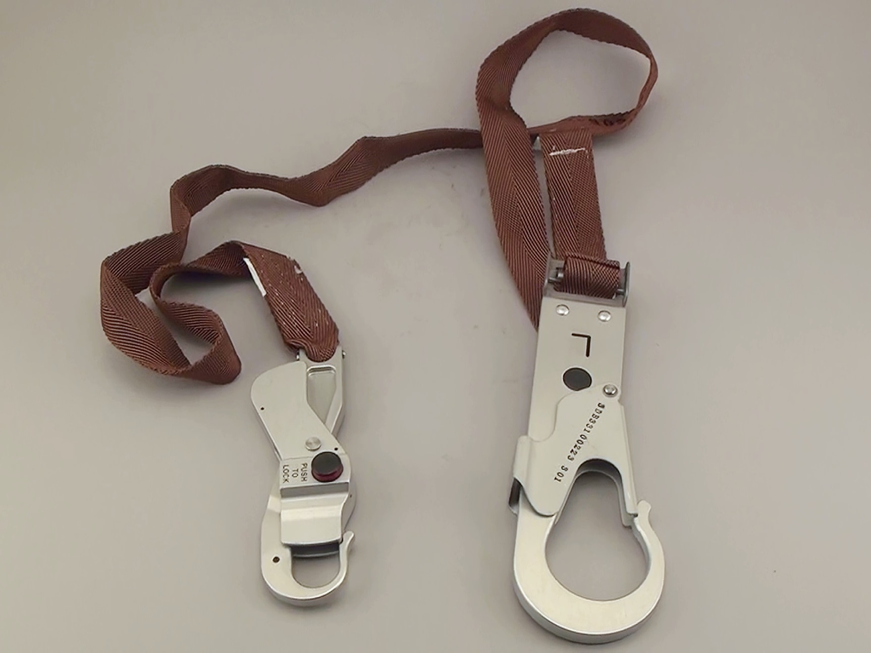
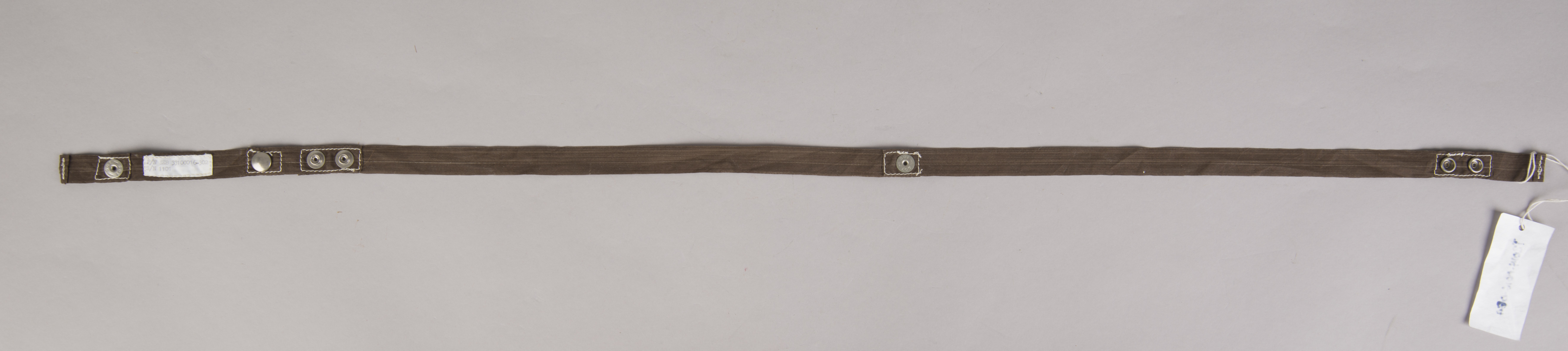
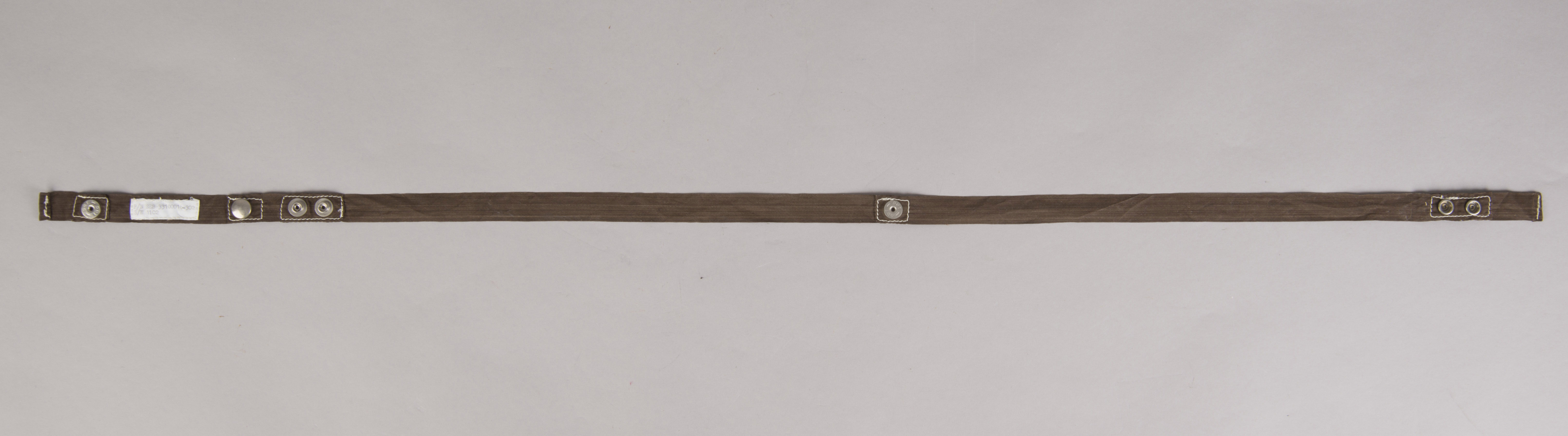
| There were two waist
tethers (also known as EVA tethers) in the LEC-Waist Tether Kit. This one
was returned to Earth. The other, presumably, was
left behind in the LM ascent stage. (Click on the image for a larger version.) |
NASM Conservation Photographs
 |
 |
 |
 |
 |
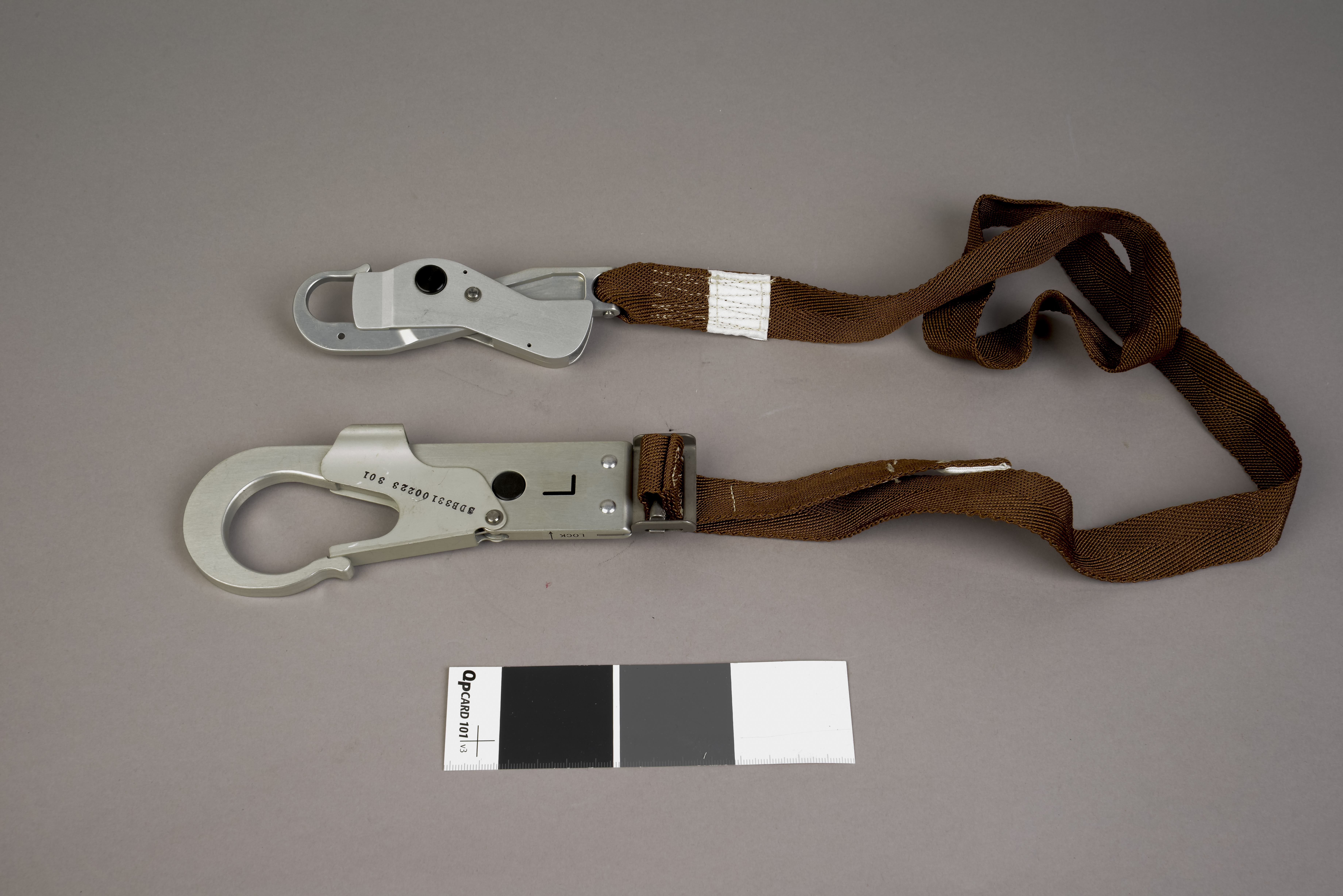 |
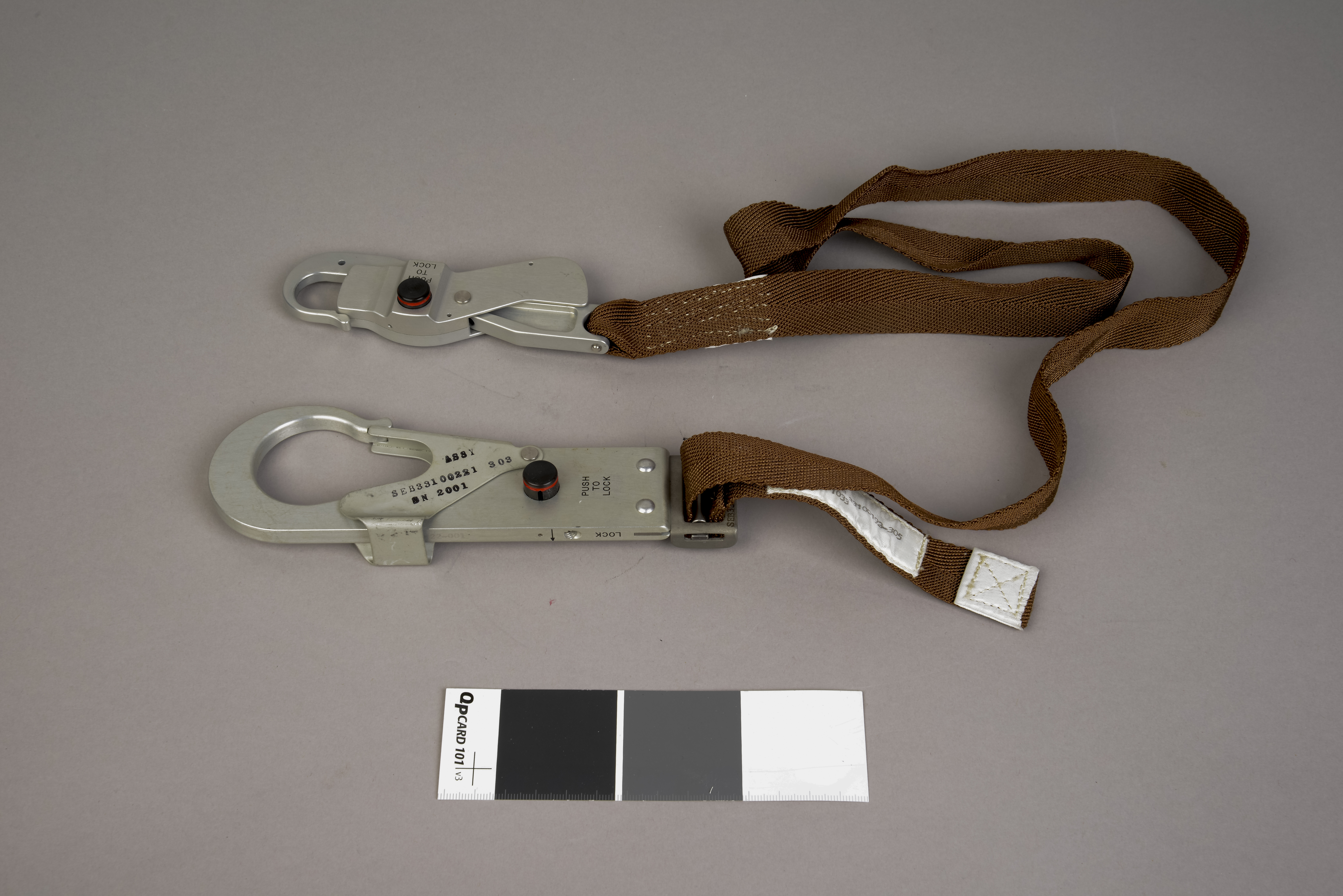
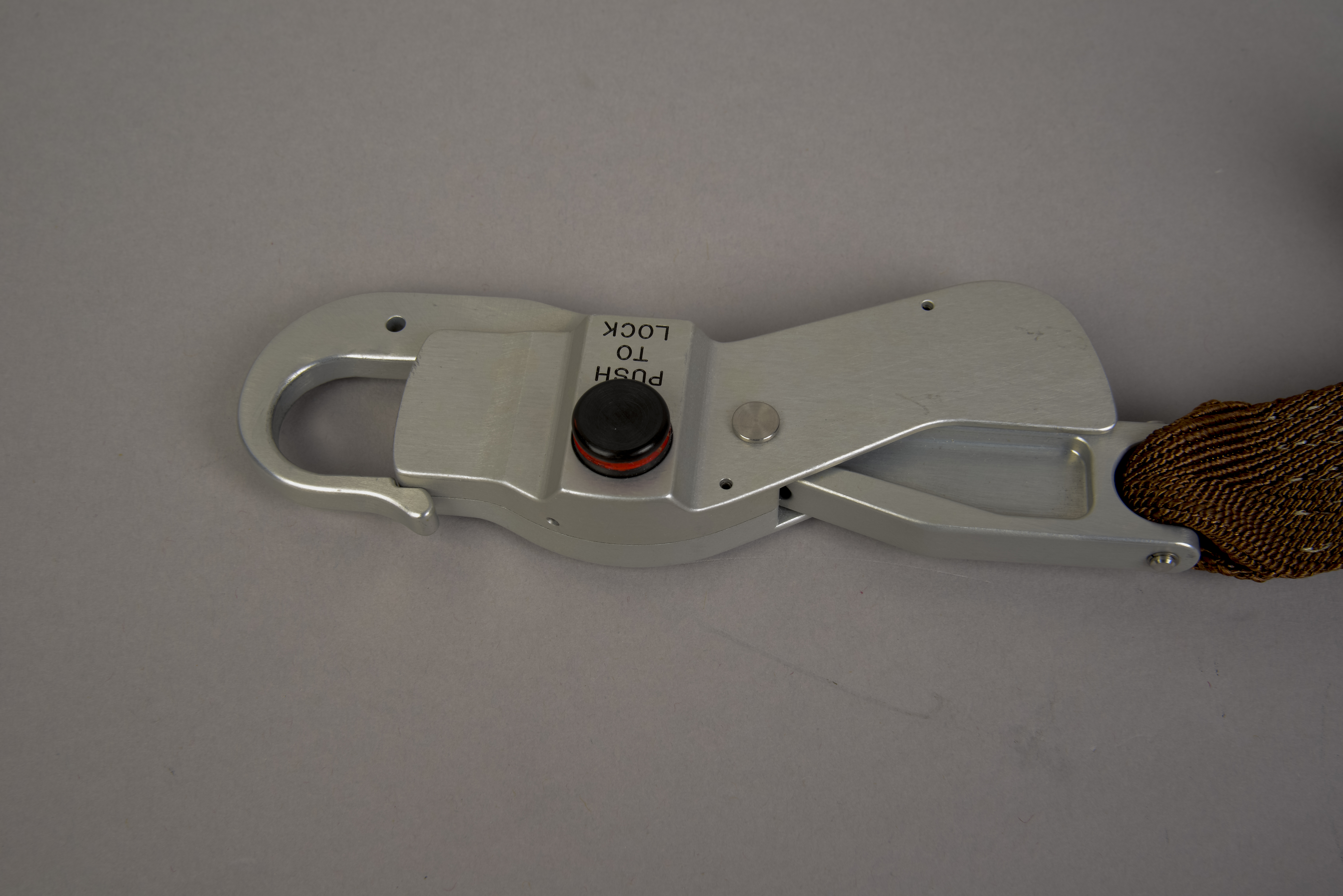
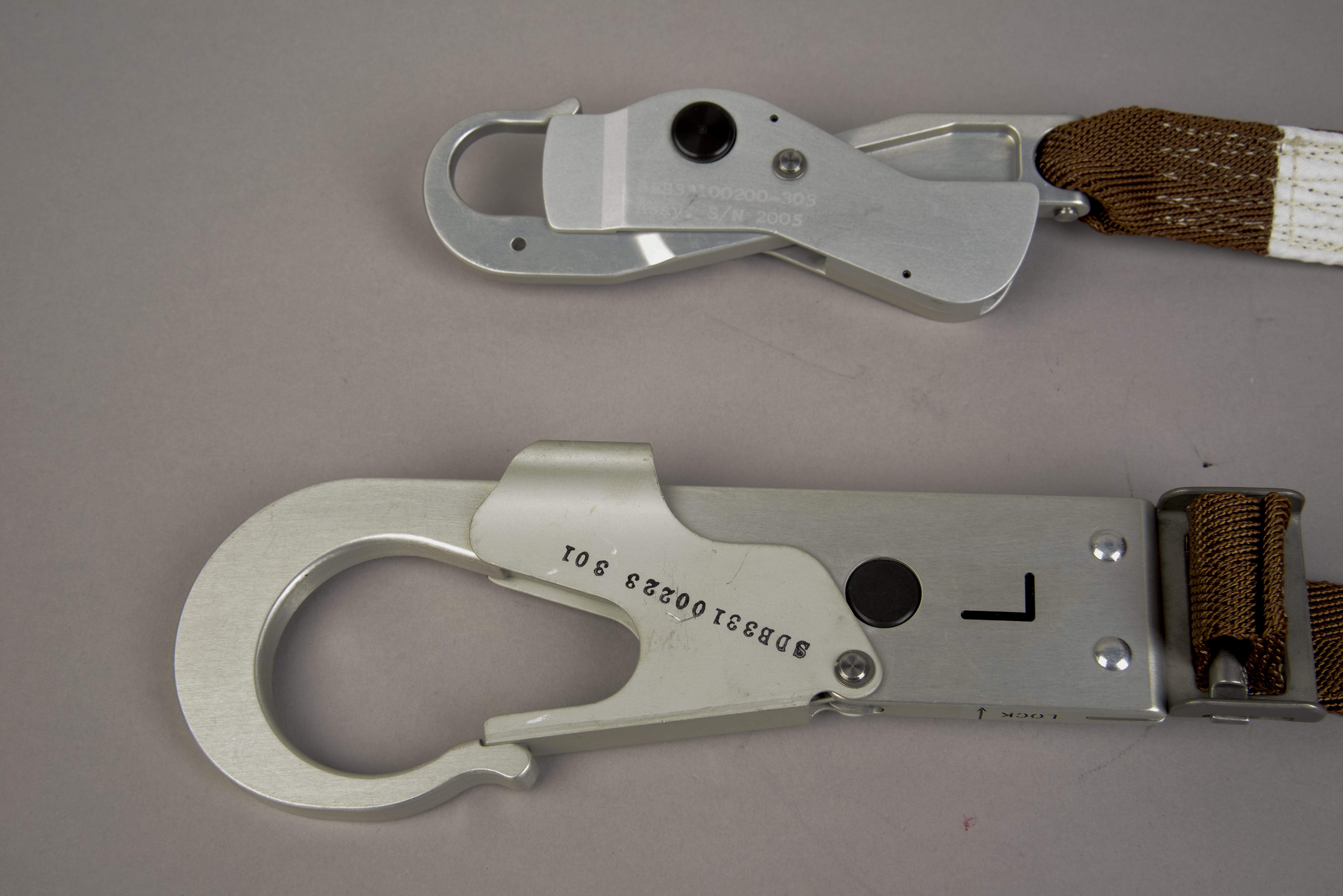
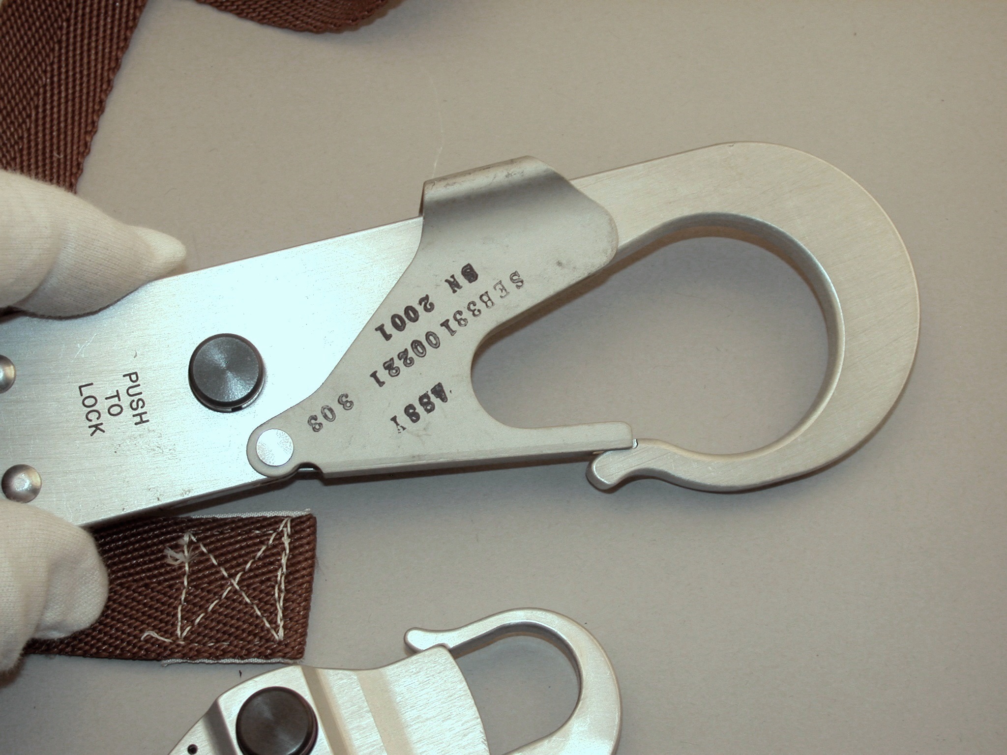
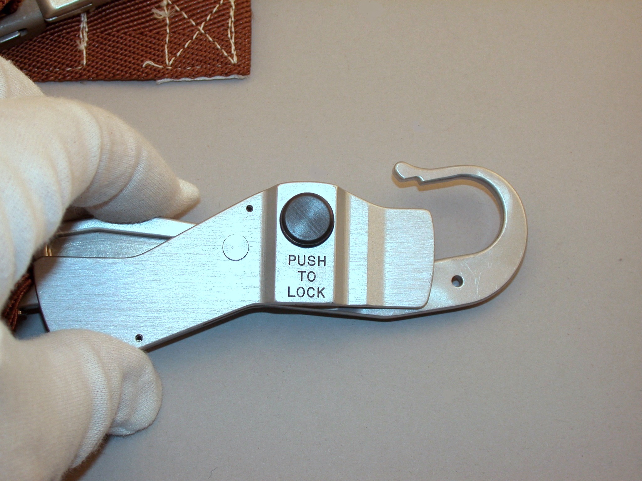
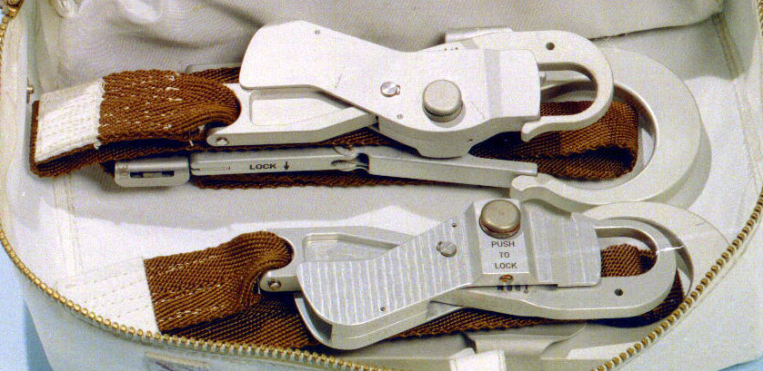
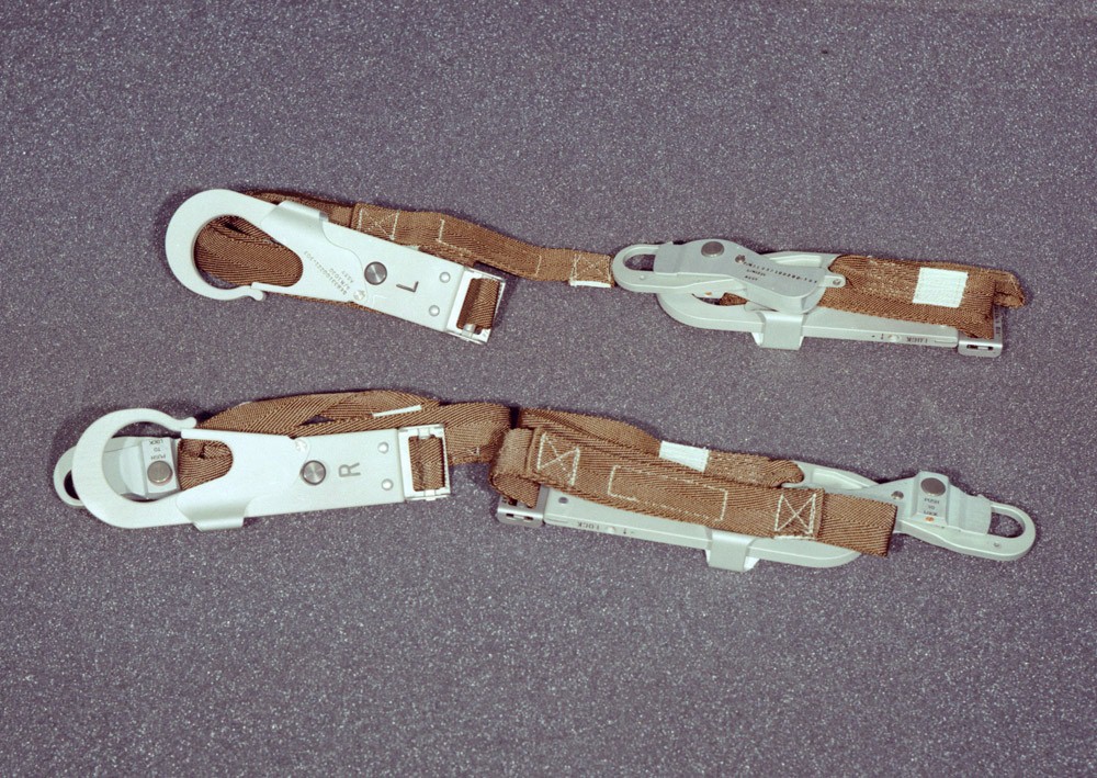
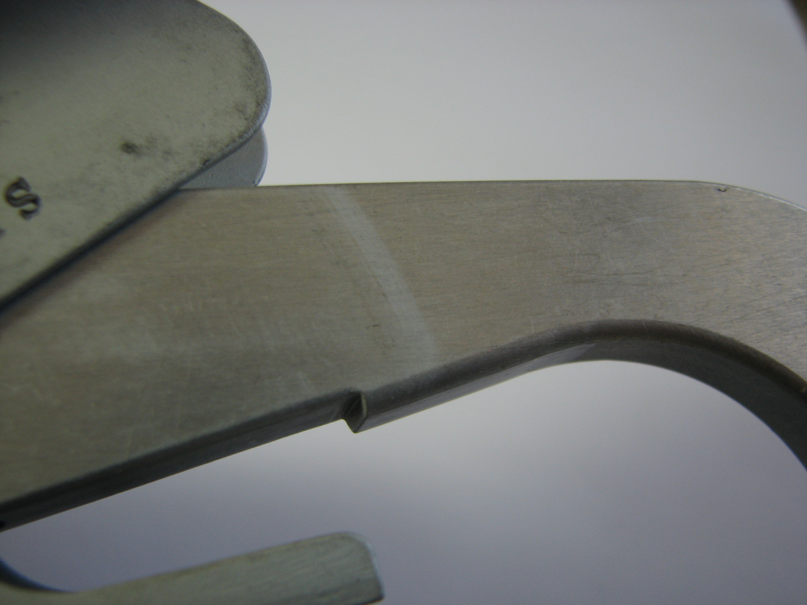
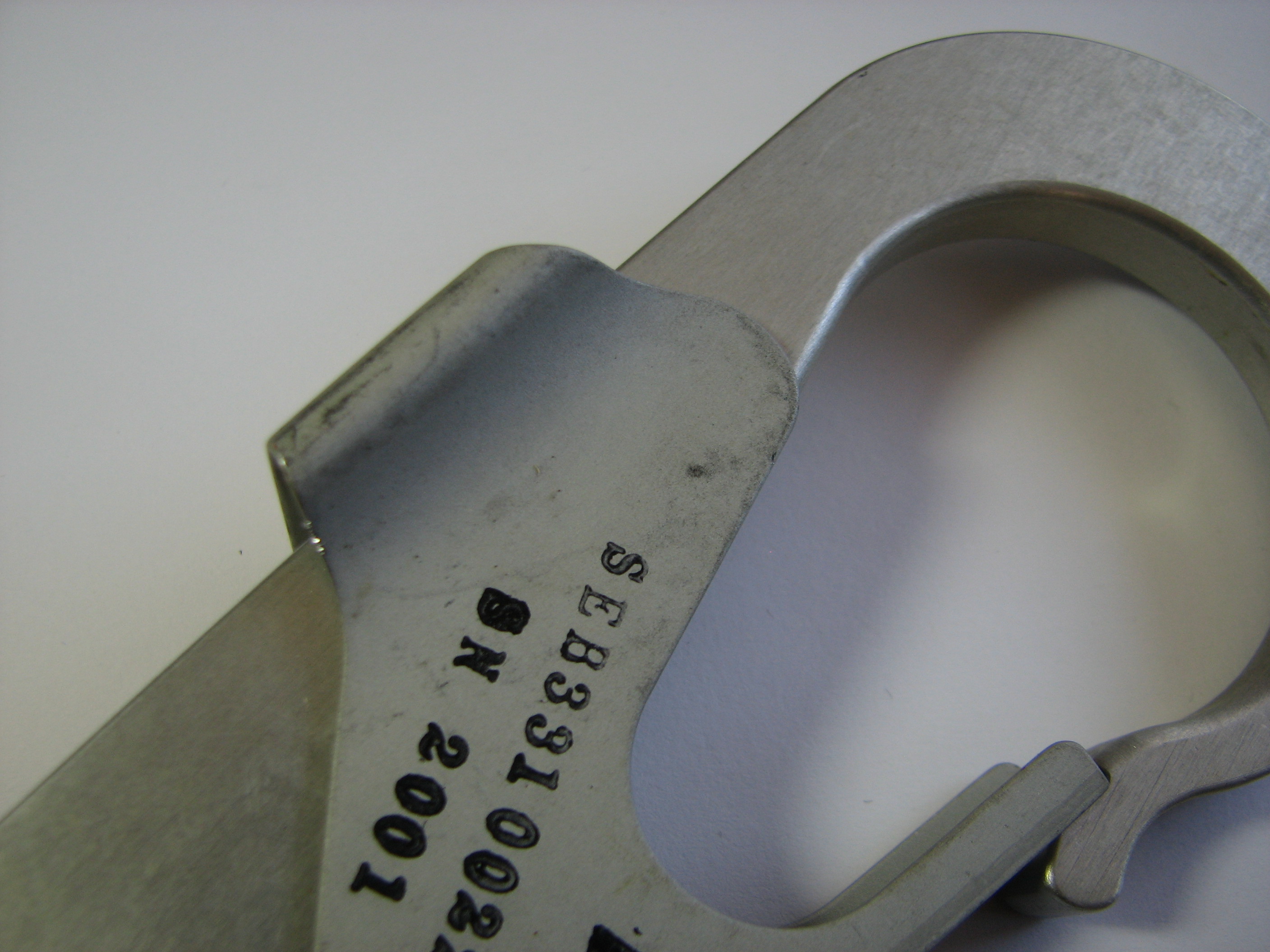
| The Waist Tether has a
snaphook at each end, one considerably larger than the
other. Each hook has a gate which allows easy attachment
to a ring attached to a suit or piece of equipment or to
the porch rail. The overall length of the tether -
from hook tip to hook tip - is 50 inches (127 cm); the
strap width is 1 inch (2.5 cm); the large hook is 7.5
inches (19 cm) long and has a maximum width of 2.25
inches (5.7 cm); the small hook is 5 inches (12.7 cm) by
1.5 inches (3.8 cm). As can be seen in the two photos in
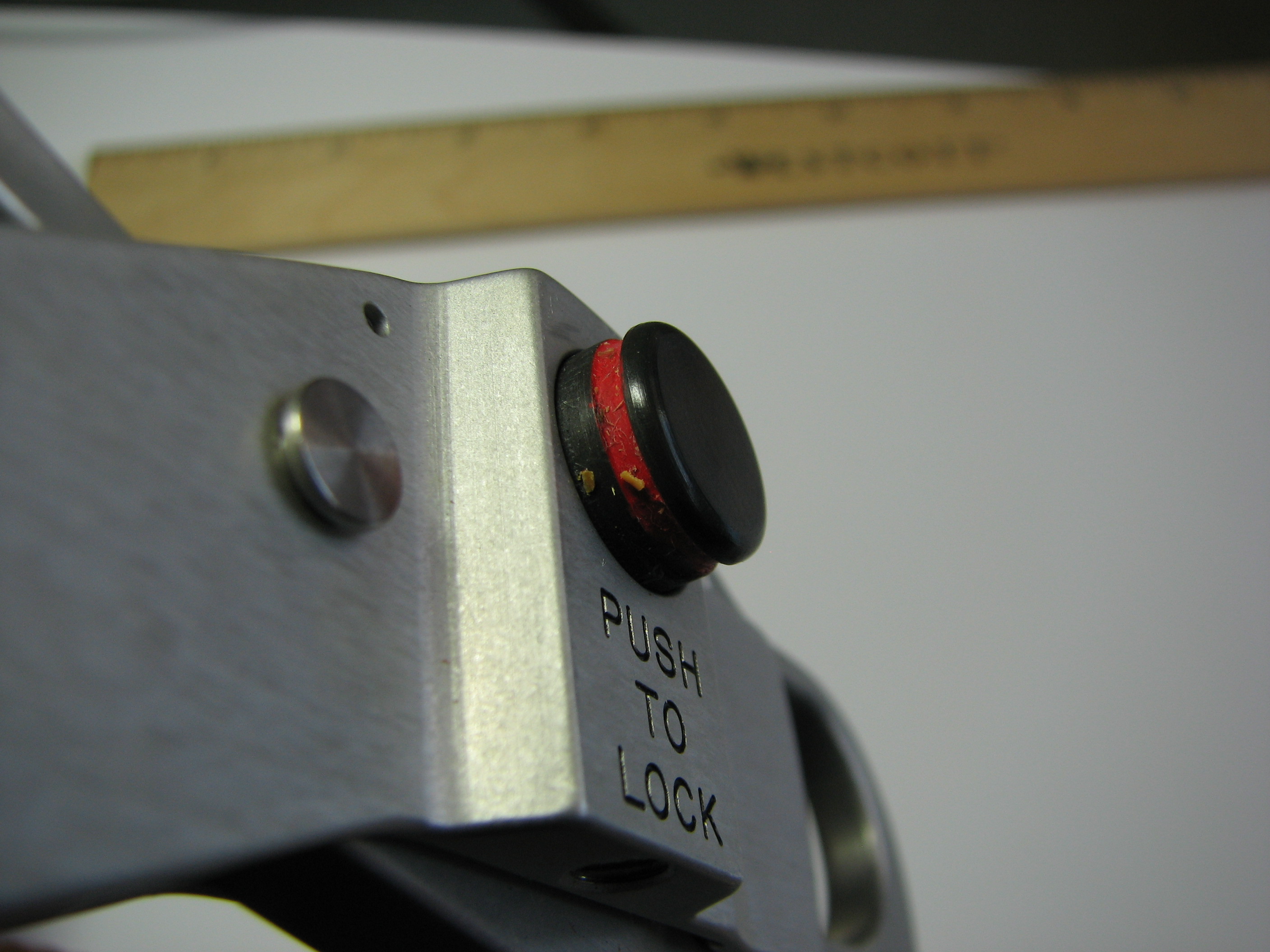
the middle row, each hook has a push-button lock.
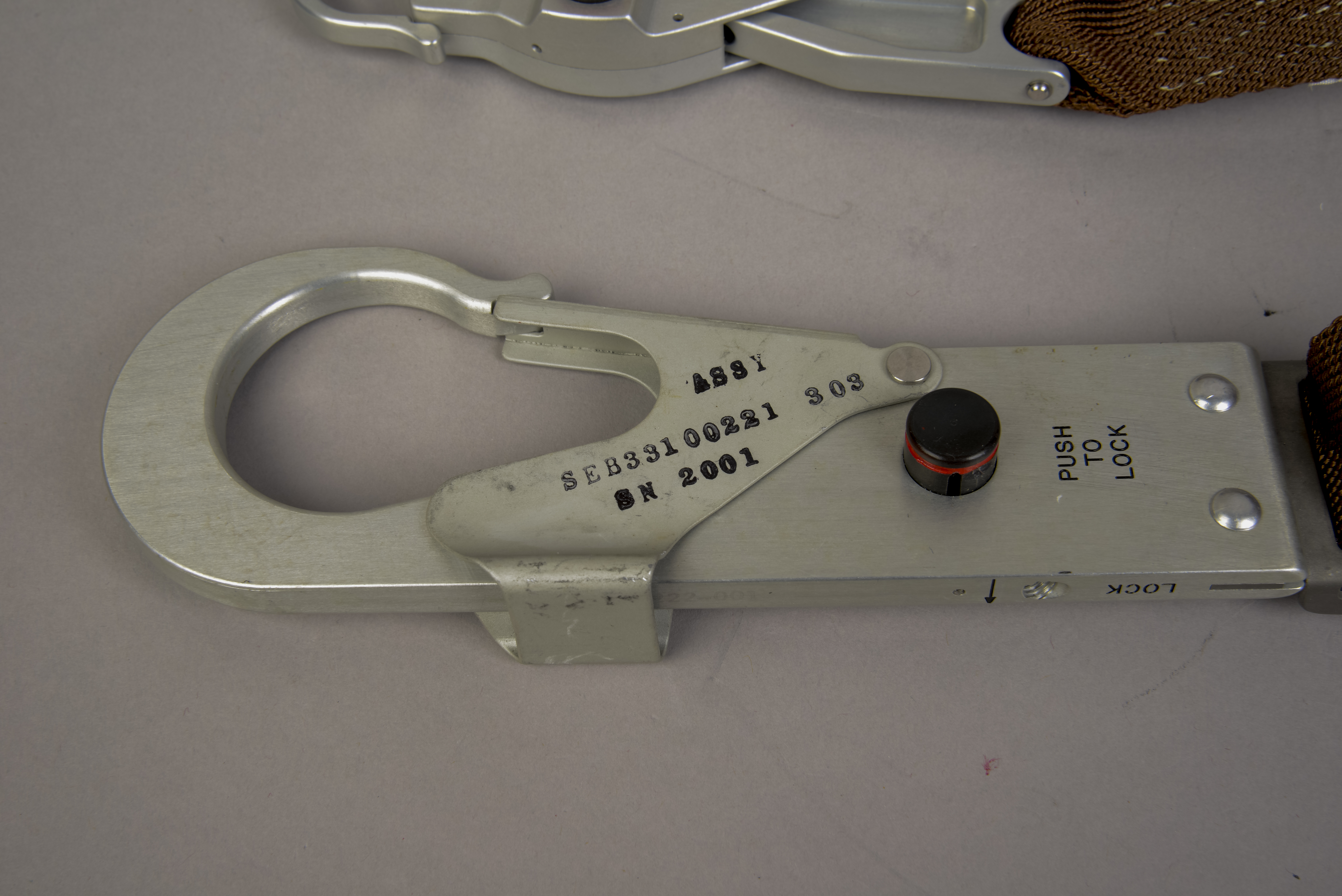
Note that one side of the large hook (middle left image)
shows the locking button in its open position, an
engraved marking 'Push to Lock', and a stamped assembly
number and serial number. The other side (bottom
left) has a large engraved letter 'L' and a stamped part
number on the gate. The gray scale card
seen in the upper left and lower right images has a
length scale marked in mm and cm. (Click on the images for larger versions.) |
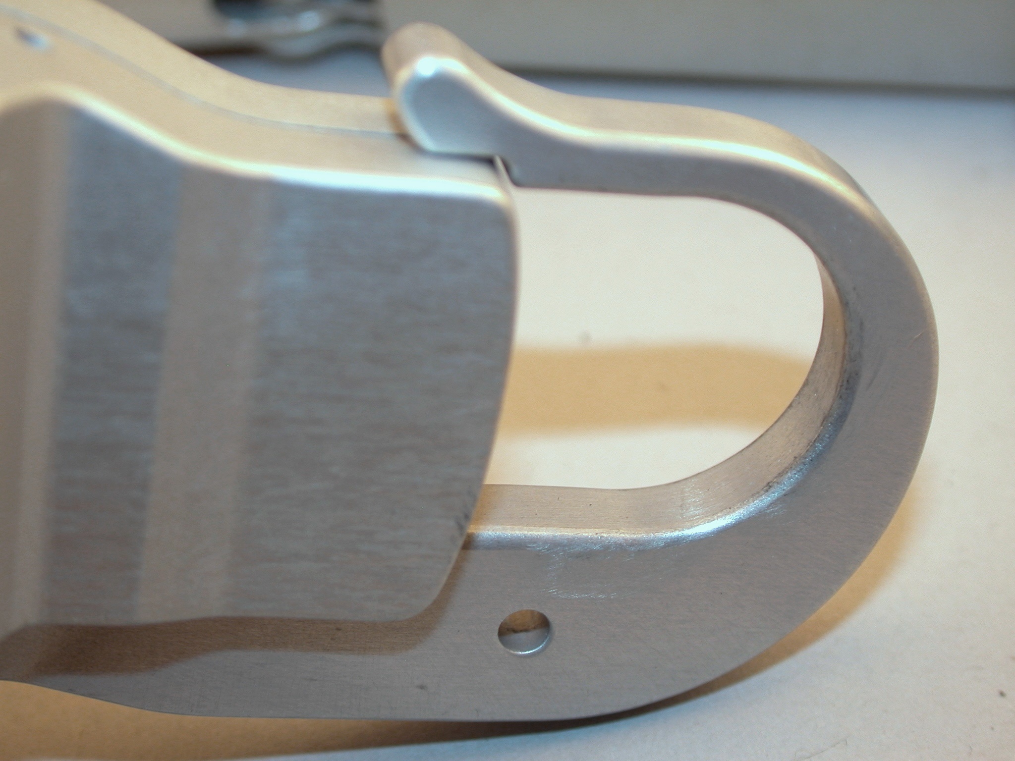
Lotzmann Close-up Photos
 |
 |
 |
 |
| Lotzmann close-ups of the
large snaphook (top row) and the small snaphook (bottom
row). The small hook shows scratches on both sides,
particular in the full resolution versions. (Click on the images for larger versions.) |
| The tethers were primarily intended for use
during an EVA transfer to the CM, should one be necessary
after rendezvous. Tethers were first
developed for use during an EVA transfer by Apollo 9
LMP Rusty Schweikart. During the Apollo 11 lunar surface EVA, Buzz took one outside and attached it to the base of porch rail on his left, in case it was needed for raising or lowering gear between the porch and the surface. It wasn't needed during the EVA. At the end of the EVA, either Buzz or Neil took it back inside the cabin in case they might need it when they returned to lunar orbit. During the rest period, Neil used one of the tethers to suspend his legs while he lay on the ascent engine cover, trying to rest. The evidence presented below clearly indicates that the tether that Neil brought back to Earth was (1) the one he used during the rest period; and (2) was not the one Buzz took outside and hooked to the porch railing for the duration of the EVA. |
Return to
Apollo 11 Lunar Surface Journal
Evidence that the waist tether Buzz hooked to the porch railing was not the one Neil brought back to Earth
| During preparations for the EVA, just prior
to PLSS and OPS donning, the list of steps on LM
Lunar Surface Checklist page 26 had the crew
remove the 80mm Hasselblad from the Right Hand Side
Stowage Compartment (RHSSC), attach a magazine, check
operation of the camera, and then put the camera back in
the RHSSC. The 80mm Hasselblad did not have a
reflective silver-colored finish and was not intended for
use out on the surface. Next, the crew were to take
the Lunar Equipment Conveyor (LEC) and one of the Waist
Tethers from the LEC/TTHR package and, five lines up from
the bottom of the page, attach the waist tether to the
80mm Hasselblad, which they apparently left in the RHSSC
while they donned the PLSSs. The next mention of the 80mm
Hasselblad in the procedures is on page 44 of the Final
Lunar Surface Procedures, just before Buzz leaves
the cabin: "Place spare Hasselblad camera on floor
at left side of +Z hatch. Check EVA tether
attached." Clearly, Buzz did not leave the tether
attached to the spare Hasselblad but, rather, took it
outside and attached it to the porch railing. Had
they needed the spare Hasselblad, it would have been easy
for Buzz to climb the ladder, reach in to get the camera
from the cabin floor, and attach it to the small snaphook
for lowering. This minor change in procedures may have
come up late in training, too late for changes to be made
in the printed procedures now available. Indeed, a
check of the Apollo 11 Crew Training documentation,
shows that Buzz did a 1/6-g training session in the KC-135
on 10 July 1969, and a photo from
that session shows Buzz attaching the large snaphook of
what is almost certainly a waist tether to the rail on his
left, just as he did at Tranquility. |
Training photo of a waist tether hooked to the porch rail

| Detail from Apollo 11
photo S69-31188,
taken at a training session on 15 April 1969 at the
Cape. It shows a waist tether hanging from the
left porch rail with a black, non-EVA Hasselblad hanging
from the small snaphook at the bottom. The Descent stage
is 323 cm tall; the tether is 127 cm from hook tip to
hook tip. (Click on the image for a larger
version.) |
Apollo 11 mission photo of a waist tether attached to the porch rail
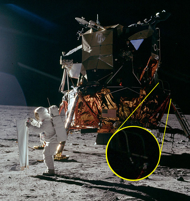
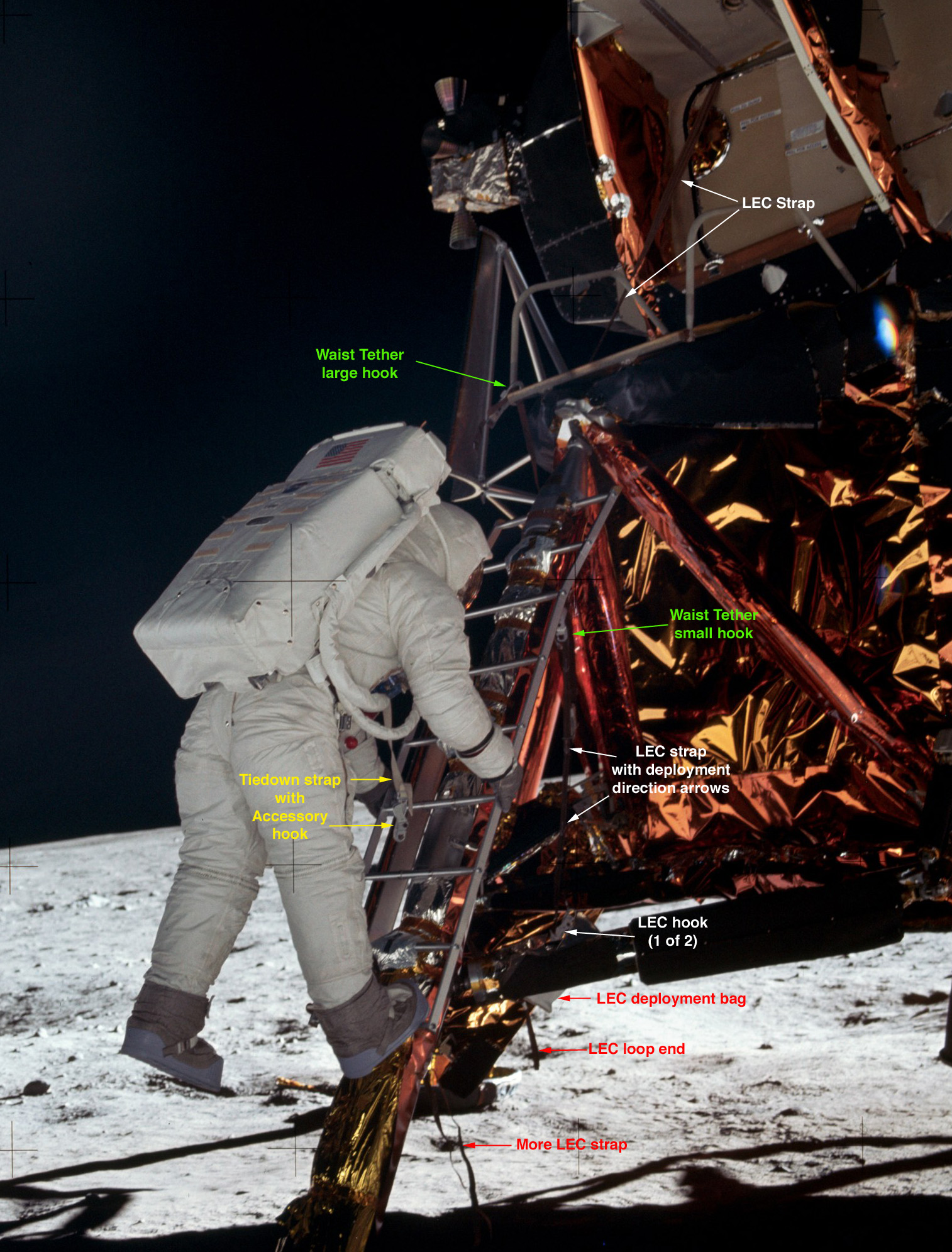
| Labeled detail for AS11-40-5868,
one of Neil's shots of Buzz coming down the ladder,
showing a waist tether hooked to the porch rail. A more complete detail
also shows the Lunar Equipment Conveyor (LEC) that they
used to transfer the surface Hasselblad down from the
cabin, including one of the two LEC snaphooks and a
large snaphook hanging at the bottom of Buzz's PGA
tiedown strap. |
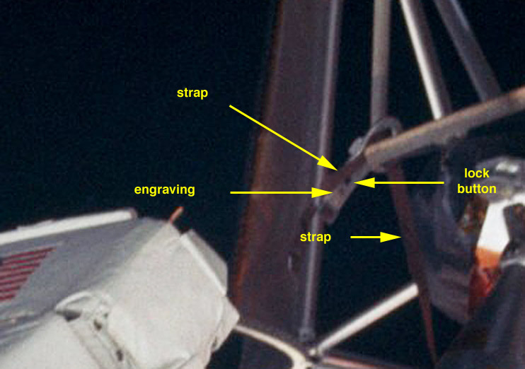
| Enhanced detail of the
large snaphook attached to the porch rail. Note
that, although the top of the hook is toward the hatch,
the strap comes around from the base of the hook on the
far side, then up onto the porch, passes around the
porch rail above the porch surface and hangs downward on
the far side. The 'lock' button is on the side
nearest the camera, with something engraved below the
button. |
| Journal Contributor Brian McInall has
examined this picture and others and shows that the Waist
Tether Buzz attached to the porch rail is not the
one Neil brought back to Earth. The hypothesis
depends on mirror symmetries between the two flown tether
straps and snaphooks. Although we don't have
relevant pre-flight images of the large hooks, we do have
an image showing differences between the small hooks and
the part of the tether straps attached to them. |
| This detail from S69-37997
shows the two waist tether in the bottom of the outer
bag that held the LEC, the waist tethers, and the
large snaphooks that the crew would attach to the PGA
tiedowns below their RCUs before the EVA. The small
hooks are facing each other with the "Push-to-Lock"
engraving up on the near hook and the
"Push-to-Lock" engraving down on the far
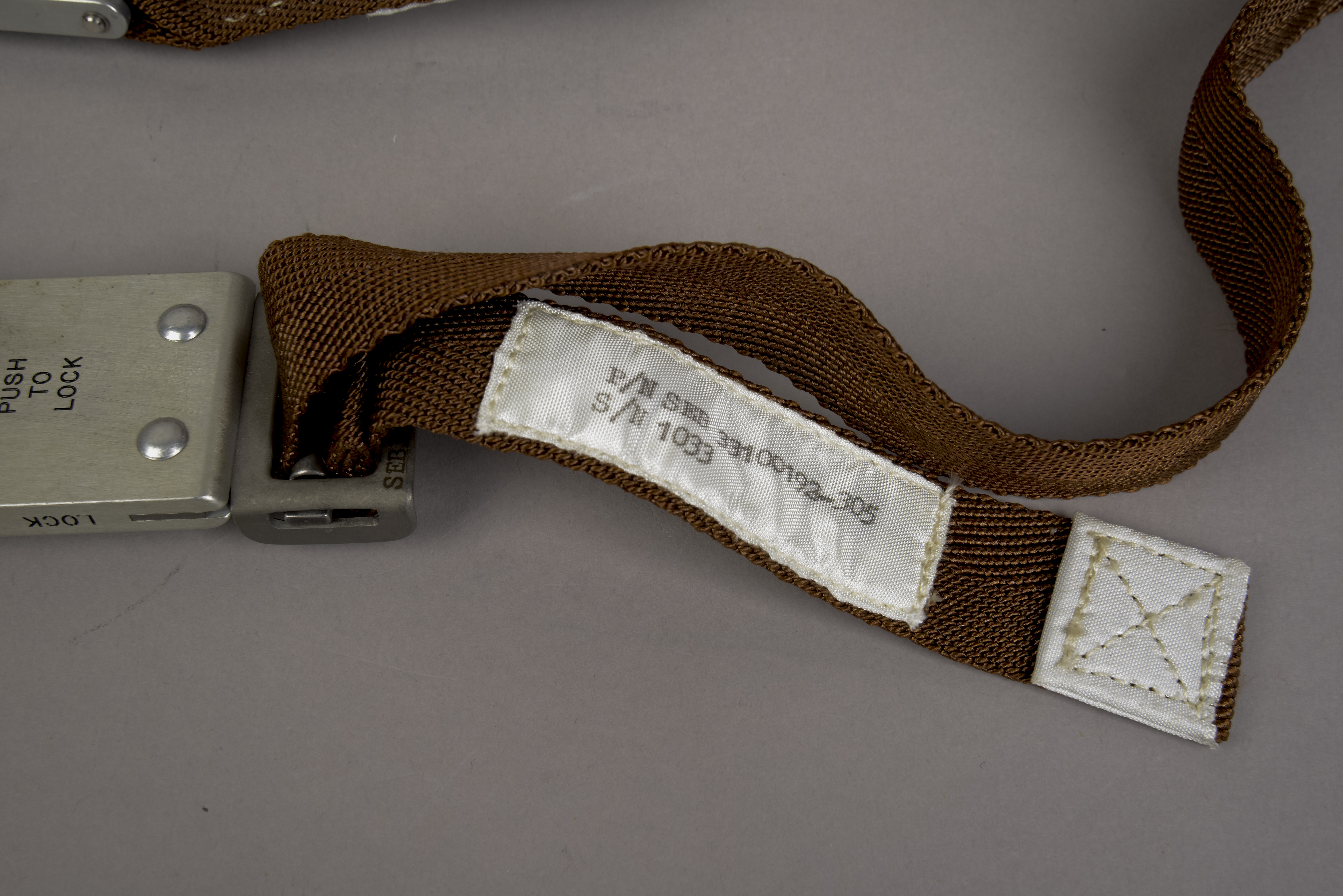
hook. Note that there is a white reinforcement
patch facing up on each of the straps, just to the left
of the strap attachment to the buckles. Note that
this photo does not show the flown tethers.
However, it was taken on 23 June 1969 and almost
certainly shows tethers identical to those flown on
Apollo 11. |
|
|
| The pair of images of the
Returned Tether shows there is a white reinforcement
patch only on one side of the strap near the small
snaphook; and one white reinforcement patch at the end
of the strap near the large hook and a longer,
Part/Serial number tag close to the
buckle on the bottom of the large hook. Because
the white reinforcement patch near the small snaphook
faces down when the "Push-to-Lock" engraving is up, we
conclude that, in the photo of the two
tethers in the LEC outer bag, the one at the back is an
identical twin of the Returned Tether. |
| Before we reconsider details from AS11-40-5868,
which was taken about 5 meters southwest of the porch, the
next figure features AS11-40-5872,
which Neil took from about 15 meters north and 8 meters
west from the porch, giving us a view of the side of the
large hook hidden in 5868. |
| This detail from AS11-40-5872
shows the ladder at center right. The highlighted
magnification at the lower right shows the front
edge of the porch slanting slightly down to the right
from the circle center and the left porch rail running
diagonally up and slightly to the left from the circle
center. Hanging down below the left edge of the
porch is the distinctive pattern of the white
reinforcement patch and, above it, the longer
Part No./Serial No. tag. The white object
the lower right in the magnification is a spacecraft
part in the background. |
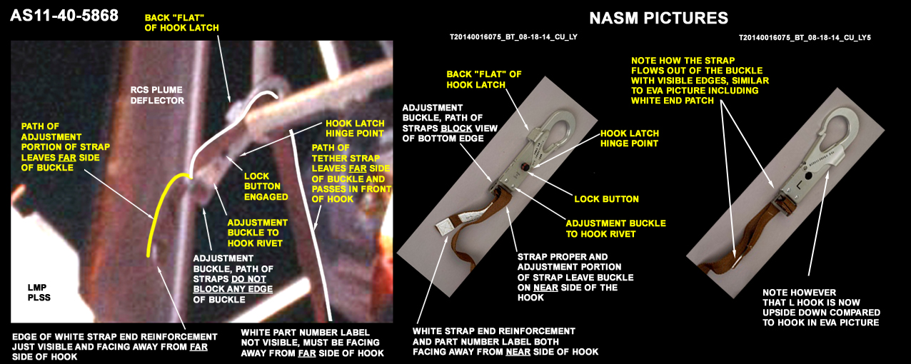
| Left image: enhanced,
labeled detail from 5868. Center image: Large hook on
the Returned Tether with the back 'flat' of the hook
latch, the buckle, and the hook gate in the same
relative positions as the hook in 5868. Right image:
Large hook on the Returned Tether turned 180 degrees
around its long axis. |
| In a comparison between the left and center
images above, the most important detail is that both the
short, adjustment portion of the strap (the portion that
includes the reinforcement patch and the Part/Serial No.
label) and the main portion of the strap leave the buckle
on the hidden, back side of the hook attached to the porch
rail (left image) while they leave the buckle on the
visible side of the buckle on the Returned Tether (center
image). Another telling detail is that, on the hook
attached to the porch rail (left image), the short,
adjustment portion of the strap shows only an edge of the
reinforcement patch. As we know from 5872, both the
patch and label are clearly visible from locations north
of the ladder. In the center image, the patch and
label are facing the viewer. In the right image, only an
edge of the patch is visible, but only because the
Returned Tether is rotated 180 degrees around its long
axis. This illustrates the mirror symmetries the two
tethers in a set. As noted previously, the main portion of the strap seen in 5868 leaves the back of the buckle, comes up an over the top of the hook in front of the back 'flat', then goes around the base of the porch rail and hangs down from there. The right image shows how the strap emergence would look from the 5872 location, ignoring the fact that the hook itself is rotated around its long axis. |
| The evidence Brian McInall presents convincingly shows that the waist tether Buzz hooked to the porch rail is not the one Neil returned to Earth. |
| John Fongheiser calls
attention to this 1969 KSC photo showing two
pairs of Waist Tethers with one large hook with an
engraved "L" and another with an "R". The two
hooks show the same mirrored symmetry noted for the
flown Apollo 11 tethers. This photo demonstrates
that the hook Buzz attached to the porch rail had an 'R'
engraved on the side facing the camera in AS11-40-5868. |
Return to Collection Image
Return to Apollo 11 Lunar Surface Journal
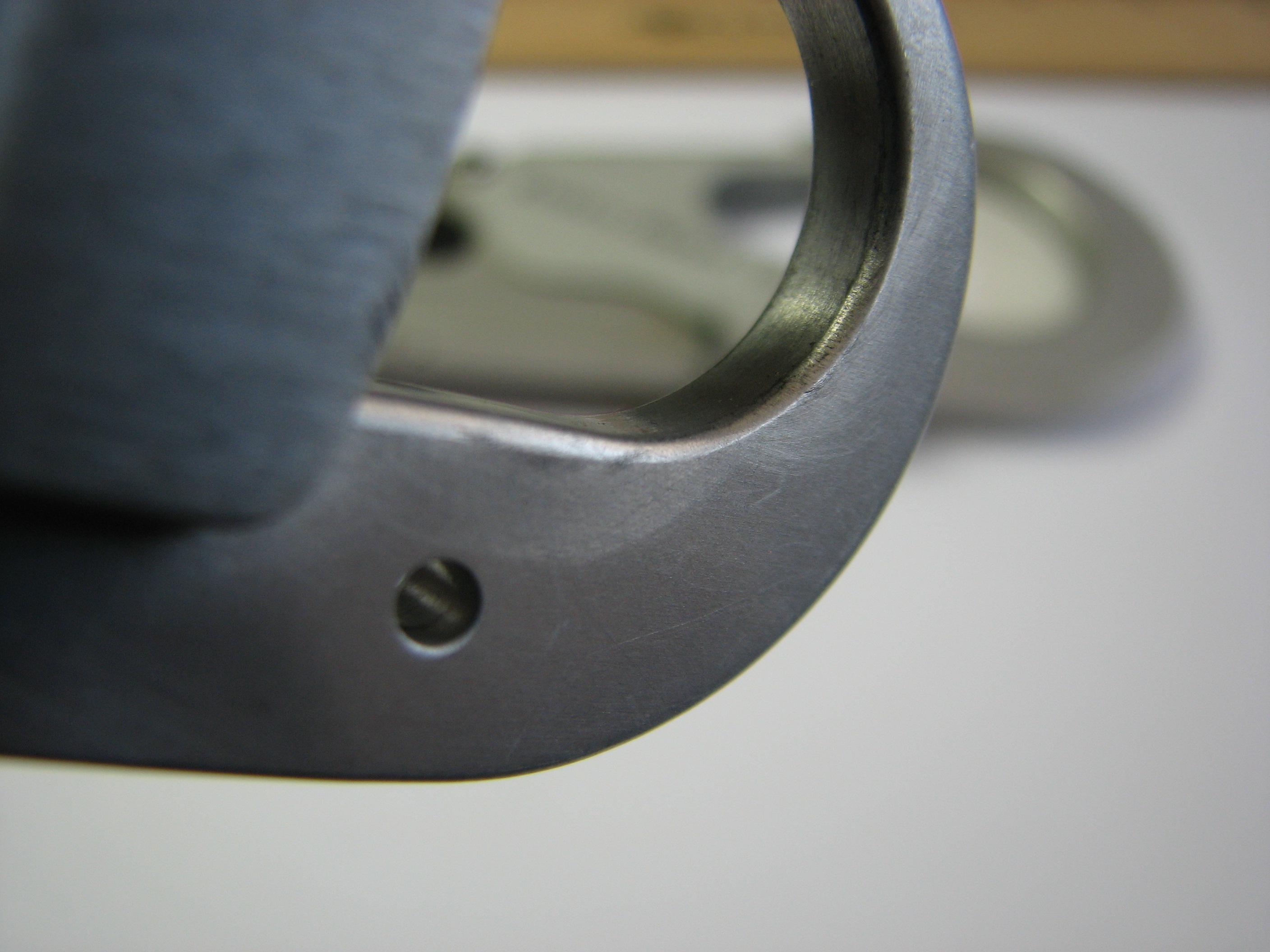
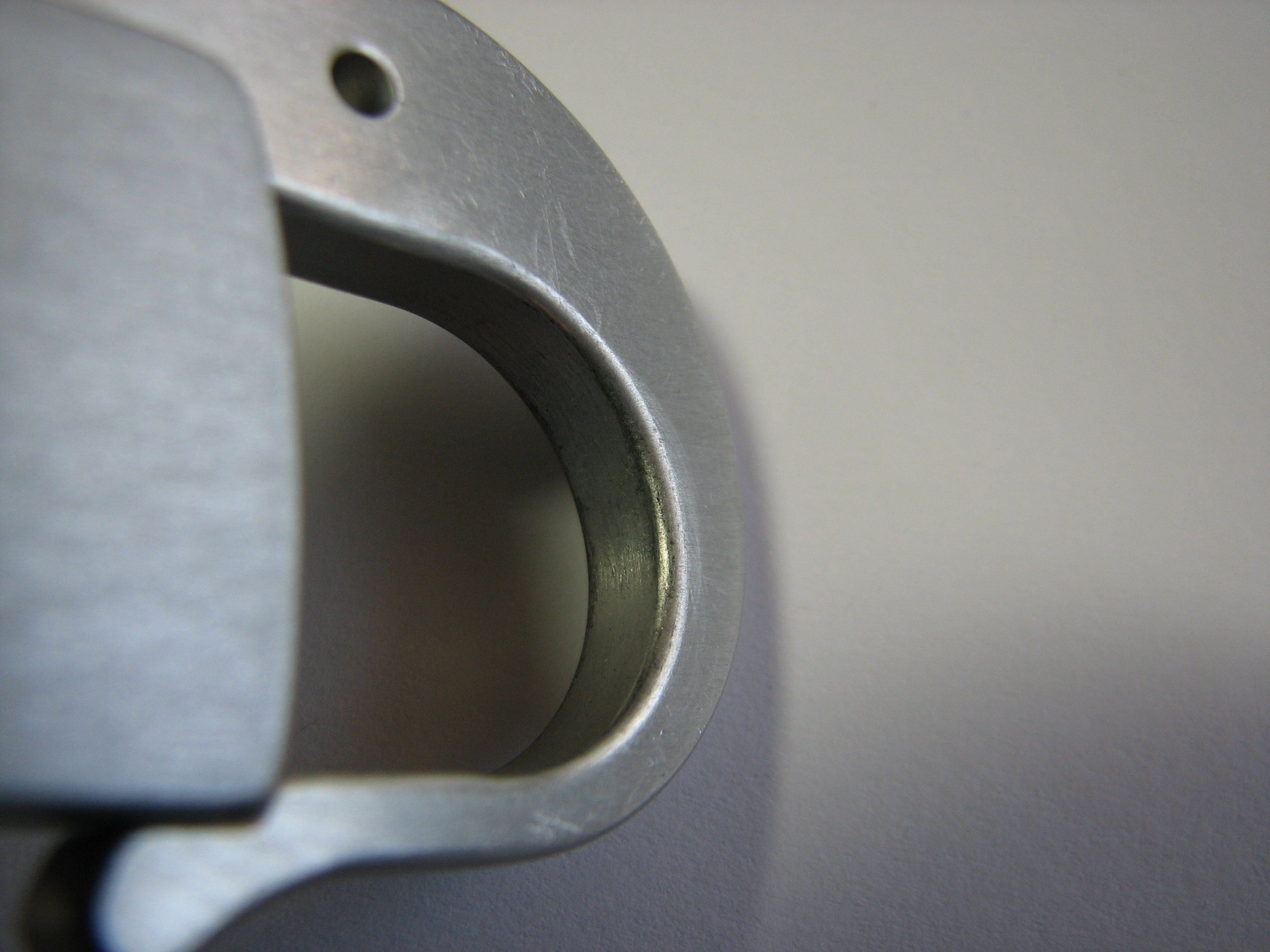
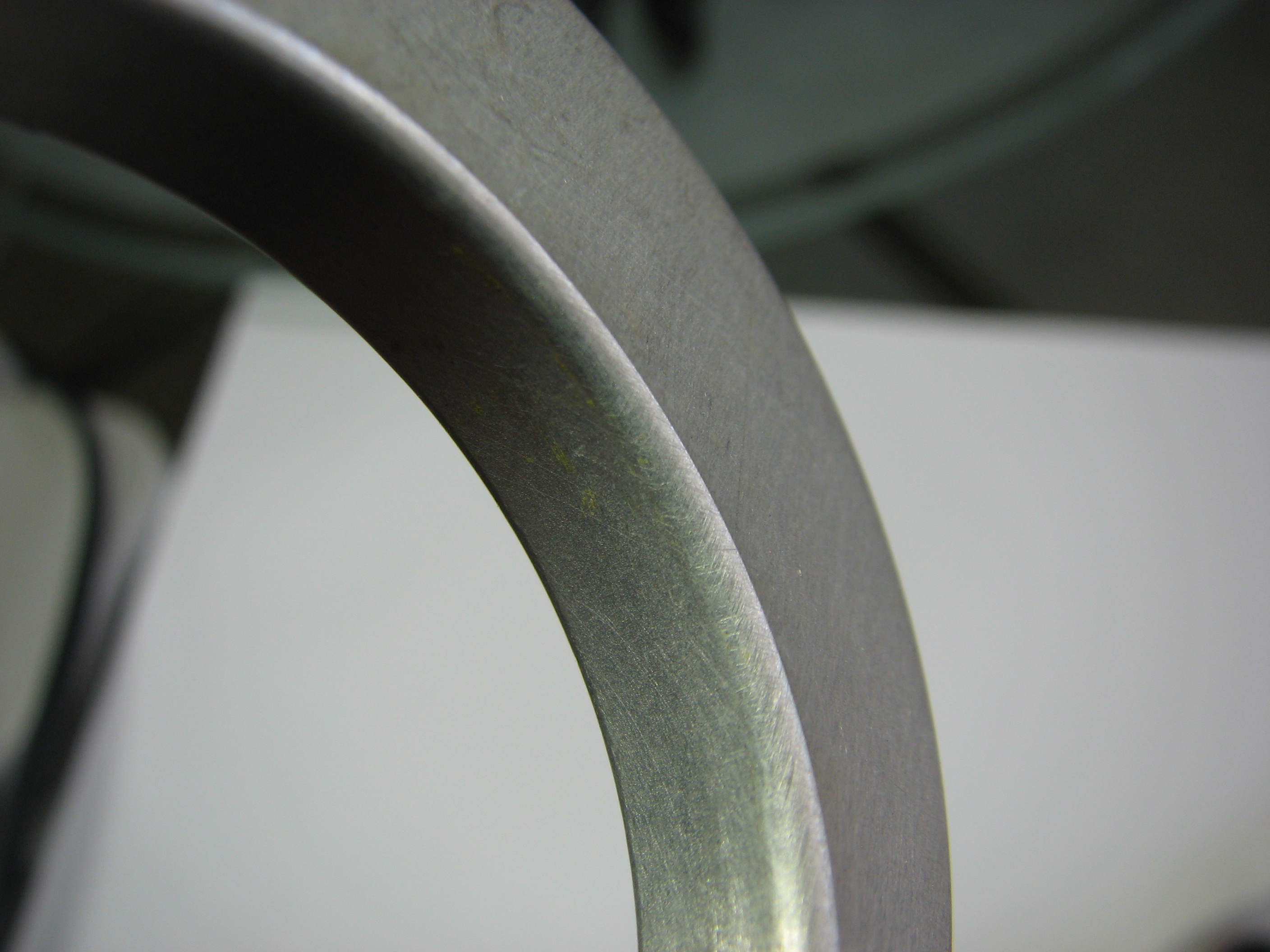
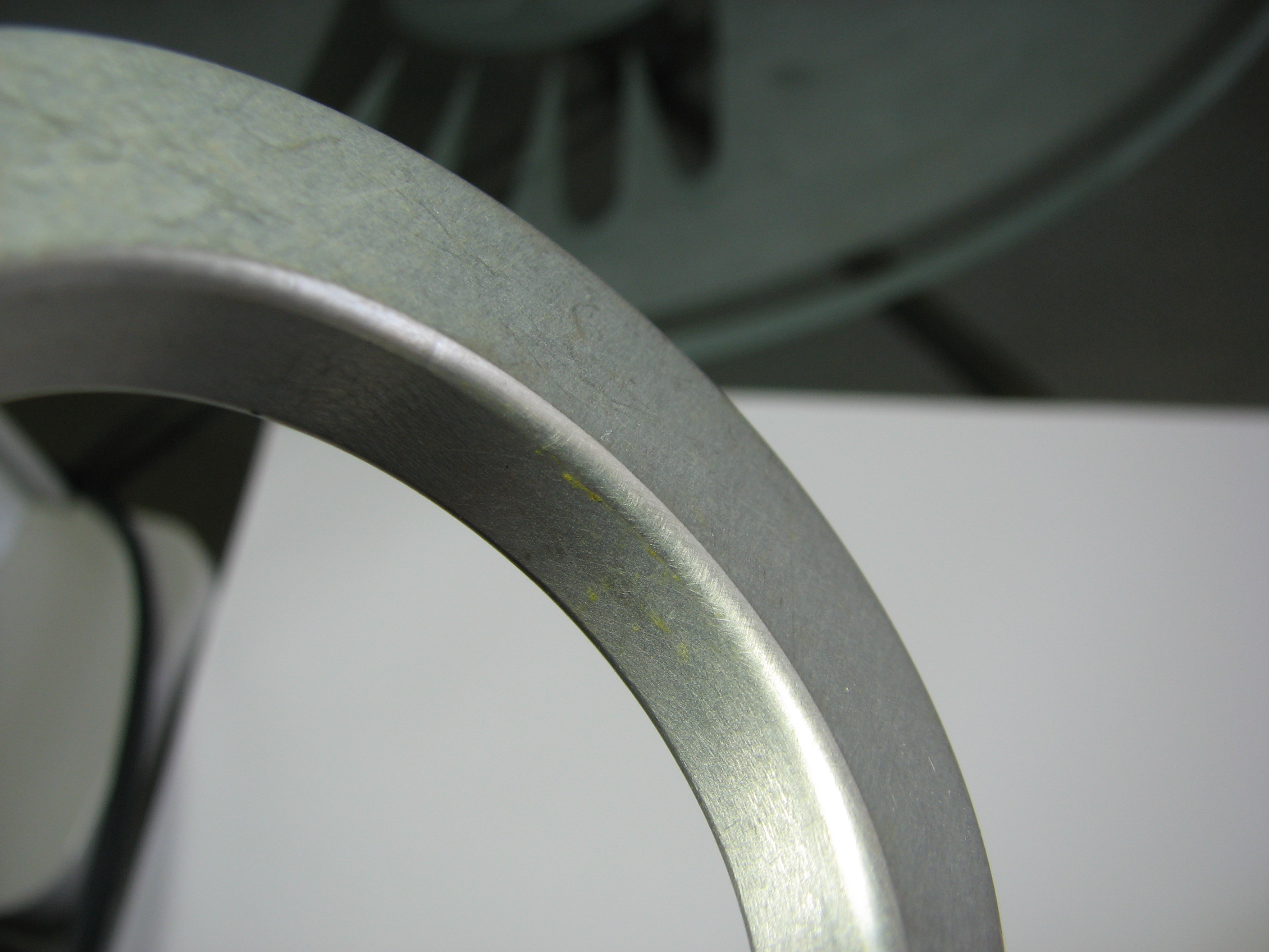
Yellow paint on the inside of the large hook
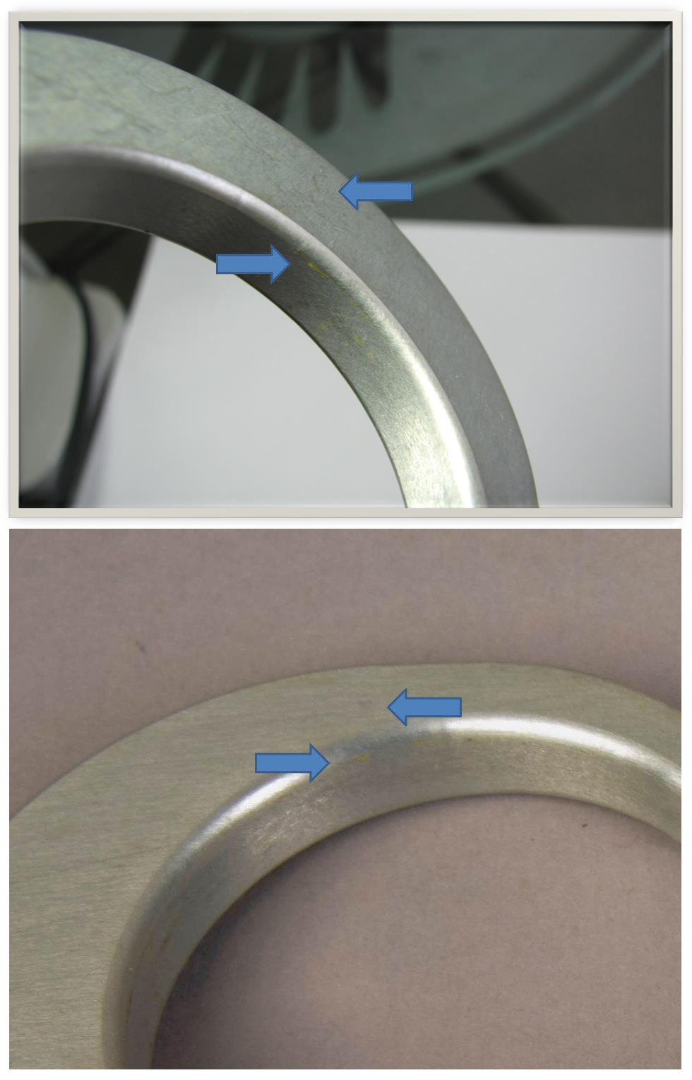
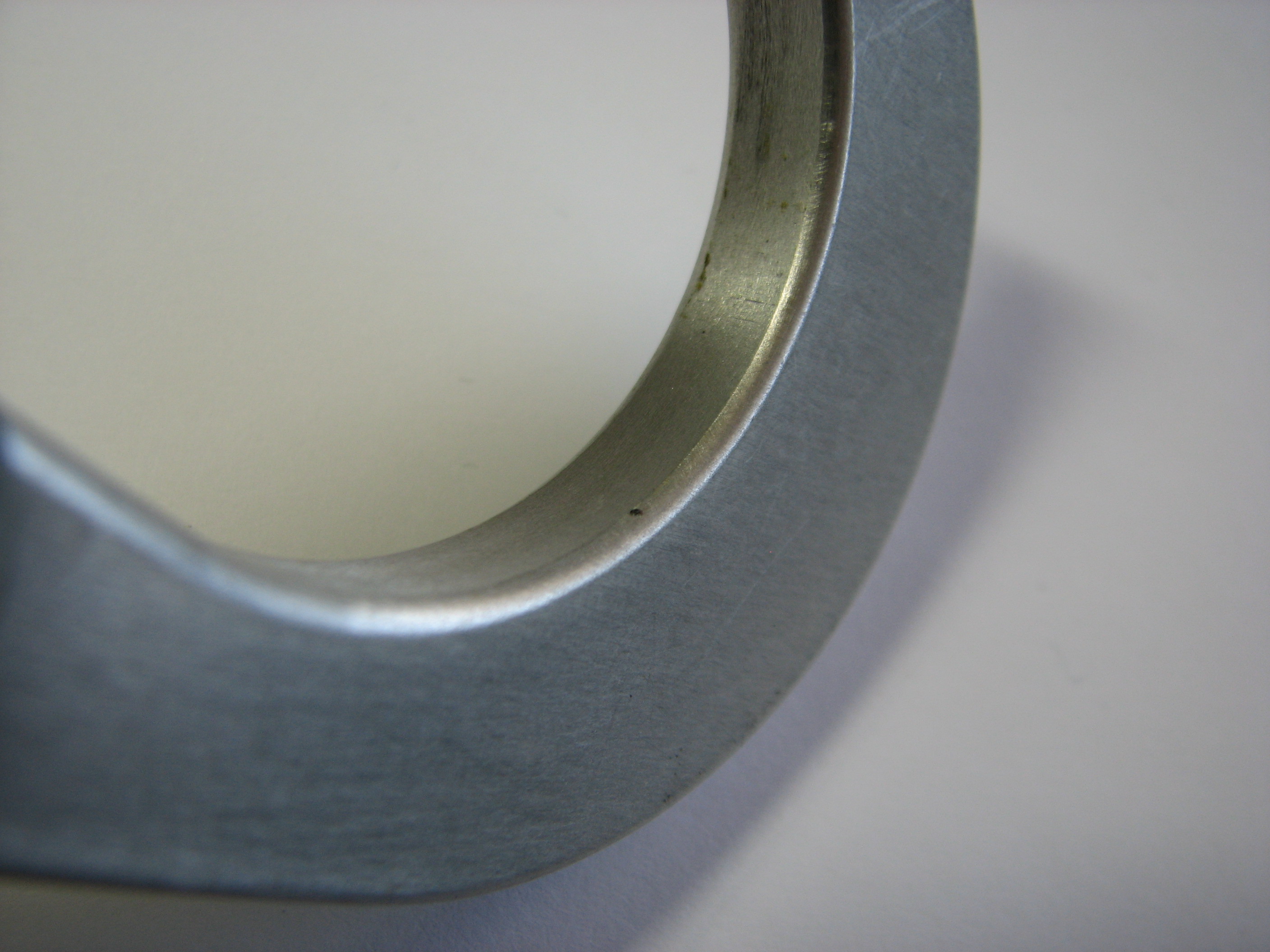
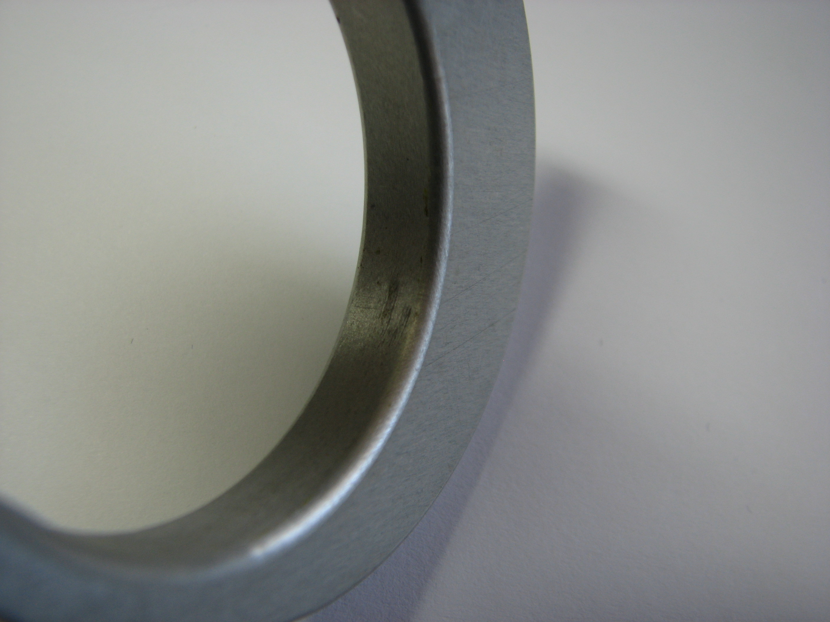
| The photo at the top is
one in a series taken of the inside of the large hook at
the suggestion of an agent for the Armstrong family
during discussions with the authors. The blue arrow on
the left points to yellow paint in the side of the
hook. The blue arrow on the right points to a
distinct scratch on the side of the hook. We were all
looking for signs of wear that might have resulted from
attachment to the porch rail. The traces of yellow paint
were a welcome surprise. The photo at the bottom was
taken by Lisa Young (National Air and Space Museum
Conservation) and shows the same distribution of yellow
paint at the same location. Agent's image used
with permission. |
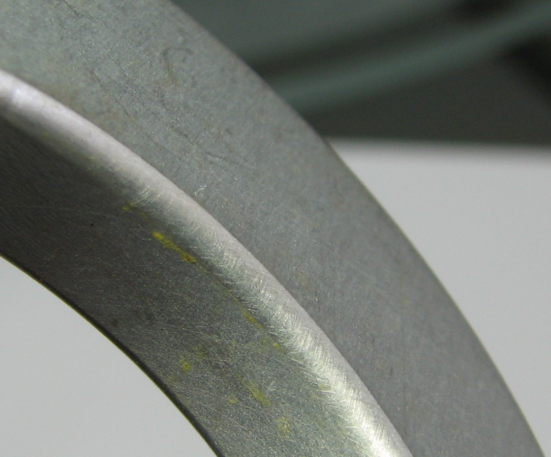
| Full resolution detail from the agent's photograph. |
Agent's photographs of the Small Hook
 |
 |
 |
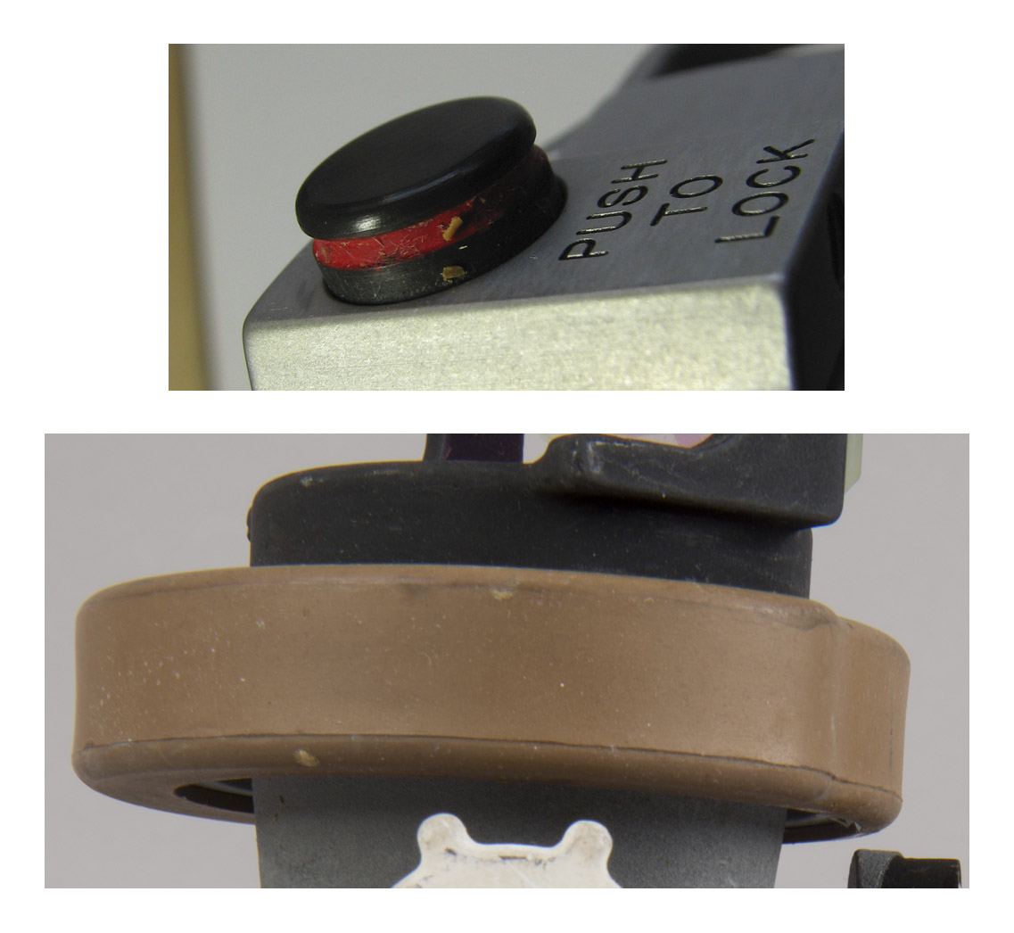
| The image on the left
shows the Lock button with what appears to be a fragment
of yellow-brown material. Although no comparison
has yet been made of the color of this fragment with the
color of the AOT particles found in the clamp 'wells',
this fragment
could be a chip off the brown ring near the combiner on
the Crewman Optical Alignment Sight (COAS), perhaps
acquired while both were in the Purse. Images
used with permission. (Click on the images for larger
versions.) |
Additional Agent's photographs of the Large Hook
 |
 |
 |
 |
 |
 |
| Images used with
permission. (Click on the images for larger versions.) |
| The presence of yellow paint in
the inside of the large hook is conclusive evidence that
the Returned Tether is the one Neil used to fashion the
'hammock' he created to keep his legs elevated during
the rest period. |
Return to Collection Image
Return to Apollo 11 Lunar Surface Journal
Use during the Rest Period
| After the EVA, Neil and Buzz doffed the
PLSSs and OPSs, stowed the rock boxes, jettisoned
equipment they would no longer need, had something to eat
and, starting about three hours fifteen minutes after the
end of the EVA, tried to get some rest. They wore their
helmets and IVA gloves, but did not have the suits
pressurized. The following is the wake-up call from CapCom Ron Evans:
After they got home to Earth, Neil elaborated on his
sleeping arrangements during the Crew Technical
Debriefing (p 10-79):
Next, during a mission review done for the Apollo Lunar
Surface Journal done in 1991, we had the following
discussion:
On page 239 in his 1973 book Return to Earth,
Buzz writes:
And, finally, on page 532 in James Hansen's authorized
Armstrong biography, First Man, we have
from Neil:
The available evidence is somewhat contradictory.
One way around the difficulty is to assume that Neil
started by sitting on the engine cover with his head
against the back wall of the cabin but, because he was
bothered by light from Earth coming through the AOT, he
devised a way to support his legs while he lay with his
back on the engine cover. The following scenario
seems consistent with most of the available evidence,
especially the presence of yellow paint on the inside of
the large hook and the fact that the opening of the
small hook is too small to fit around the tubing that
comprises the guard. However, it may not represent what
Neil actually did. We will never know. |
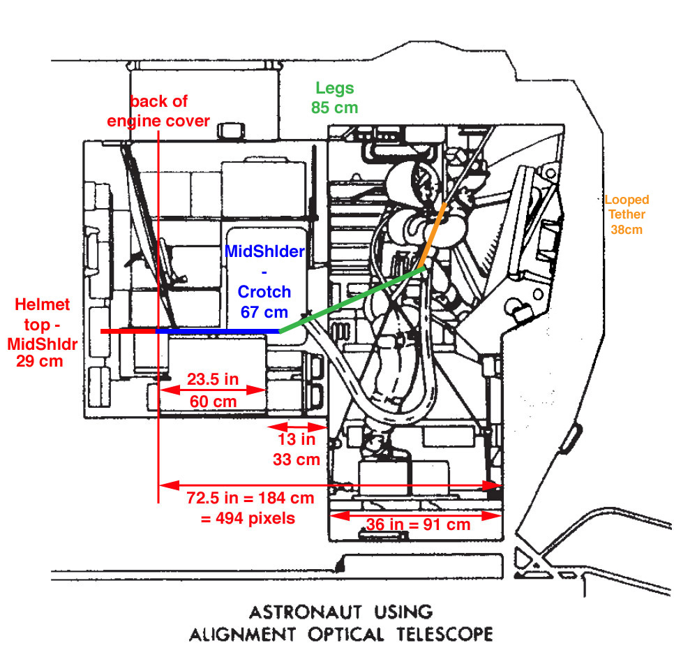
| Side view of the cabin
with the Ascent Engine cover 60 cm in diameter with 33
cm of midstep forward of it. The cabin floor from the
midstep to the hatch is 91 cm. Note that the
diagram does not specifically refer to the Apollo 11
LM. In particular, we don't have any specific
information about the configuration of the 'shelf' Neil
mentioned. Based on measurements made by suit
manufacturer ILC, he was 179 cm tall; his crotch height
was 85 cm; his mid-shoulder height was 152 cm; and the
distance from his mid-shoulder to the top of his helmet
was 29 cm, where we have added 2 cm to represent
clearance above the top of his head. The heavy blue line
represents Neil's back from his crotch to mid-shoulder.
We have positioned the blue line so that the front edge
of the engine cover is about midway between his crotch
and waist, which would have provided some buttock
support. This puts his mid-shoulder behind the cover and
we assume that, with his helmet supported by the 'shelf'
he mentions, his neck is adequately supported. |
| As shown in the next figure, one of us (K.G.) devised a way to rig the Waist Tether on the AOT guard that provides a loop about 38 centimeters deep. With Neil's torso positioned as indicated by the heavy blue line, he could have supported his legs by putting his boot heels in the loop as indicated. |
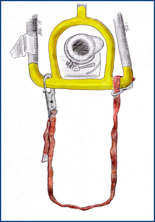
| Lotzmann visualization of
a loop formed from an EVA tether attached to the AOT
guard, with the large hook clipped to the guard on one
side, the loop formed below the guard, and small hook
passed around the horizontal part of the guard on the
other side before being attached to the strap. The
tether is 127 cm long from hook tip to hook tip.
The small hook is 12.7 cm long and, by
wrapping the strap around the AOT guard as indicated,
the effective length is reduced to roughly 100 cm.
Neil's shoe size was 9 1/2, indicating a length of
10.5 inches (26.7 cm and a width of 4.2 inches (10.7 cm).
Both feet would have fit side-by-side on the loop with
the ankles resting on the bottom of the loop. The
length of strap supporting Neil's ankles would be, say
24 cm, the back of Neil's ankles would be about 38 cm
below the AOT guard, enough to provide clearance for the
length of his boots. (Click on the image for a larger
version.) |
Return to Collection Image
Return to Apollo 11 Lunar Surface Journal
Helmet Tie-Down Straps (2)
 |
 |
| Helmet Tie-down Straps (2). Part Number SEB 33100016-302: S/N 1101 (top) S/N 1102 (bottom). For launch from the Cape, these were stowed in the Right Hand Side Stowage Compartment (RHSSC) next to the LMP's flight station. The LM crew transferred their helmets over from the Command Module before undocking. We have been unable to find any references to the tie-down straps being used during LM operations. Each of the straps is 39.5 inches (100 cm) long and 0.75 inches (1.9 cm) wide. (Click on the images for larger versions) |
Return to Collection Image
Return to Apollo 11 Lunar Surface Journal
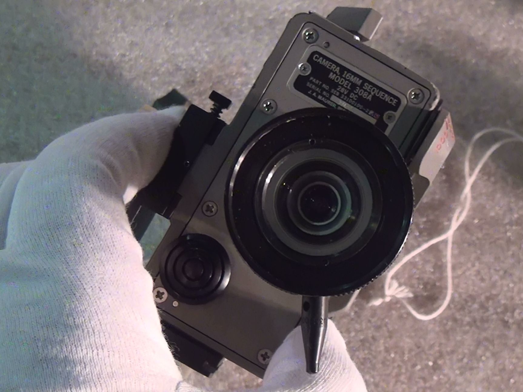
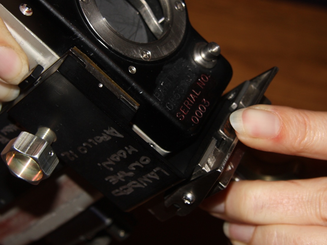
Data Acquisition Camera (16-mm movie)
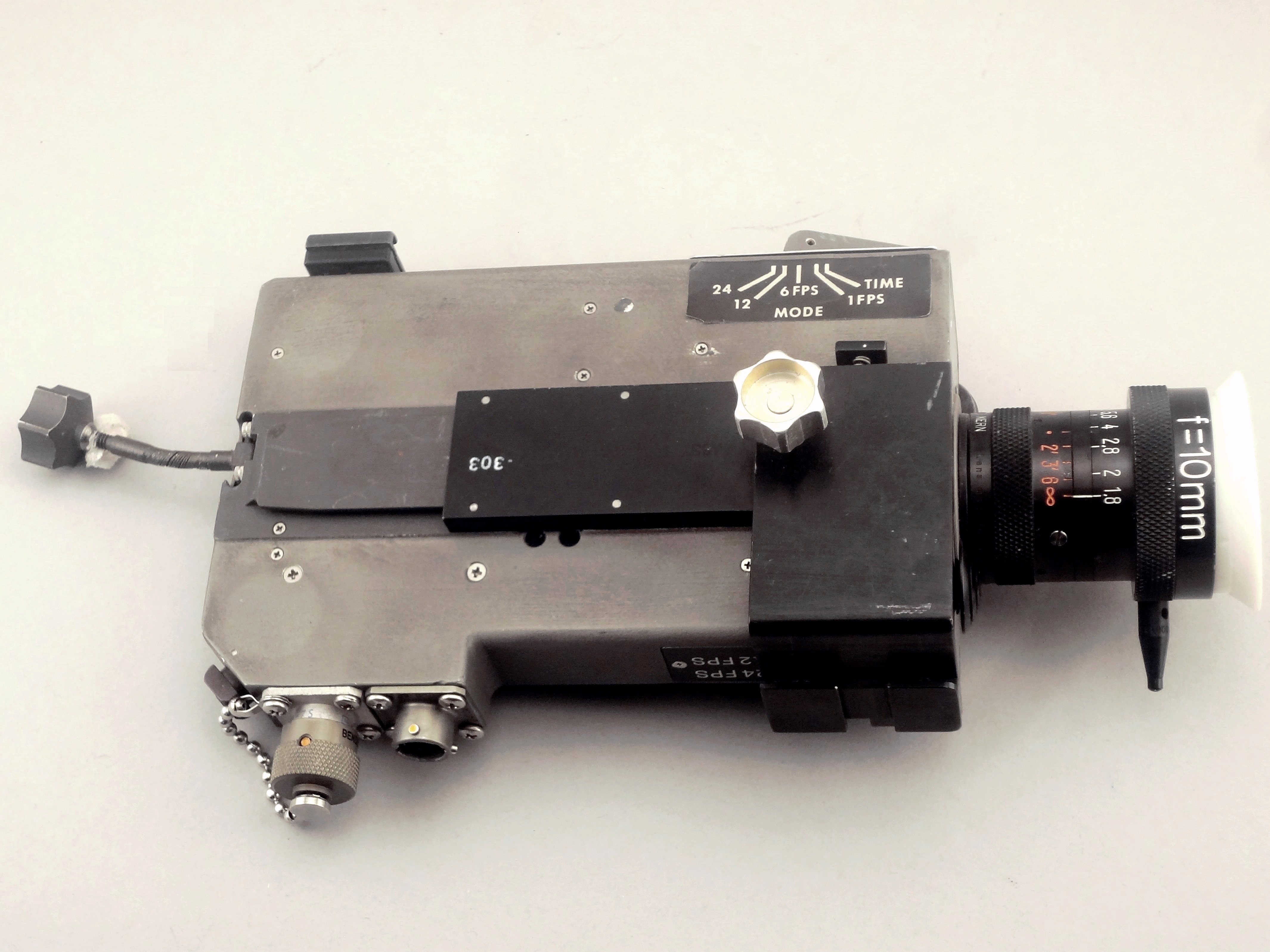
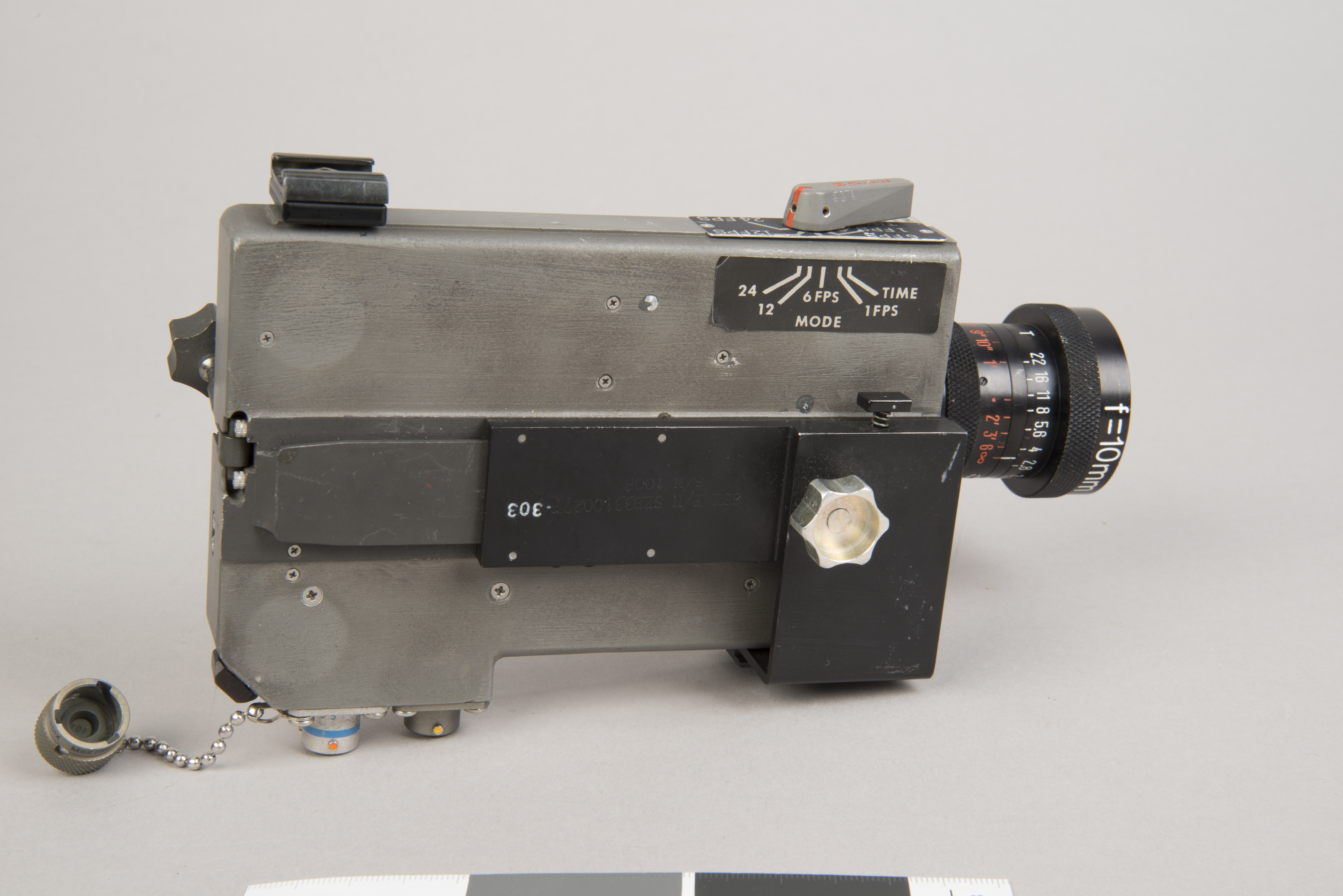
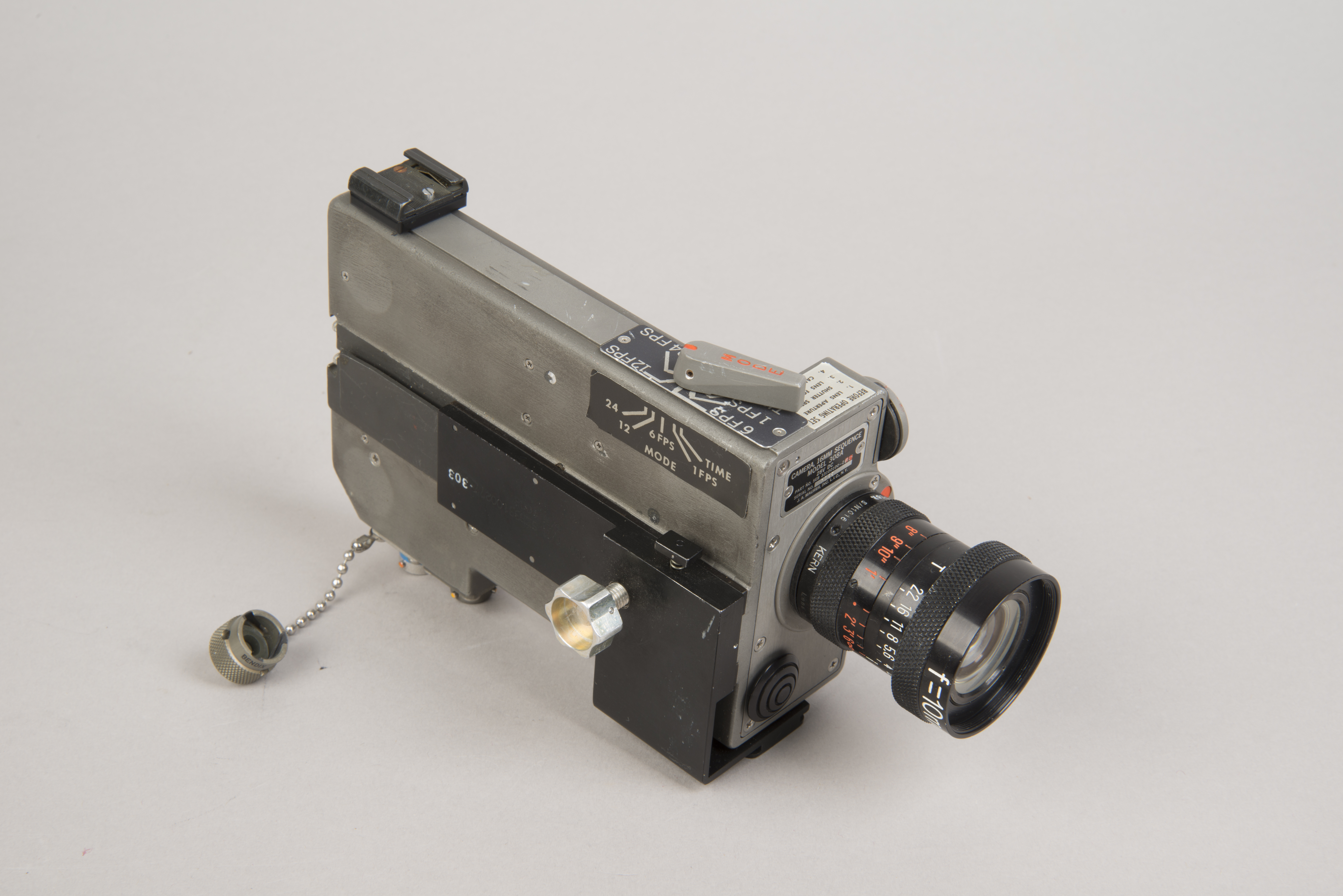
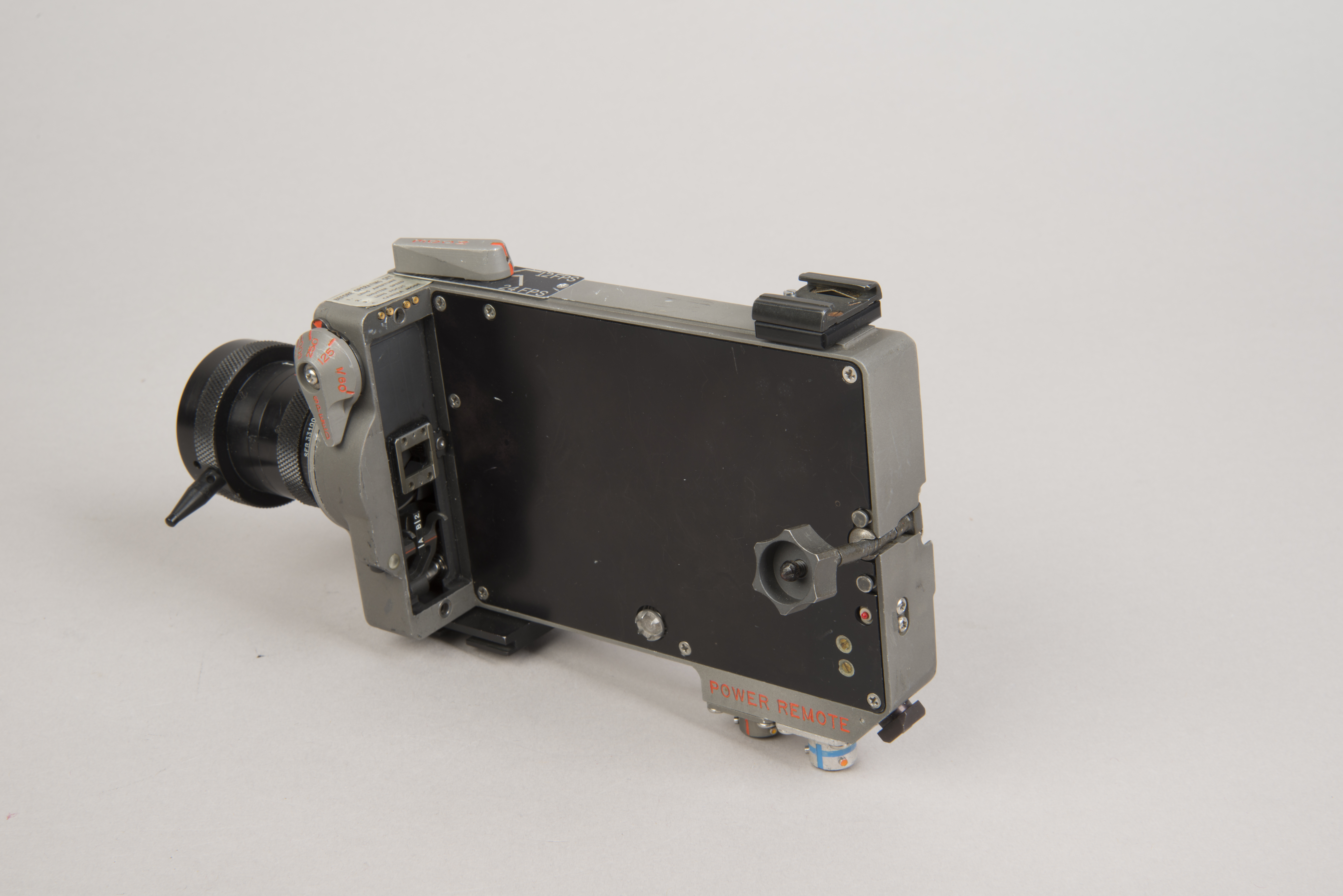
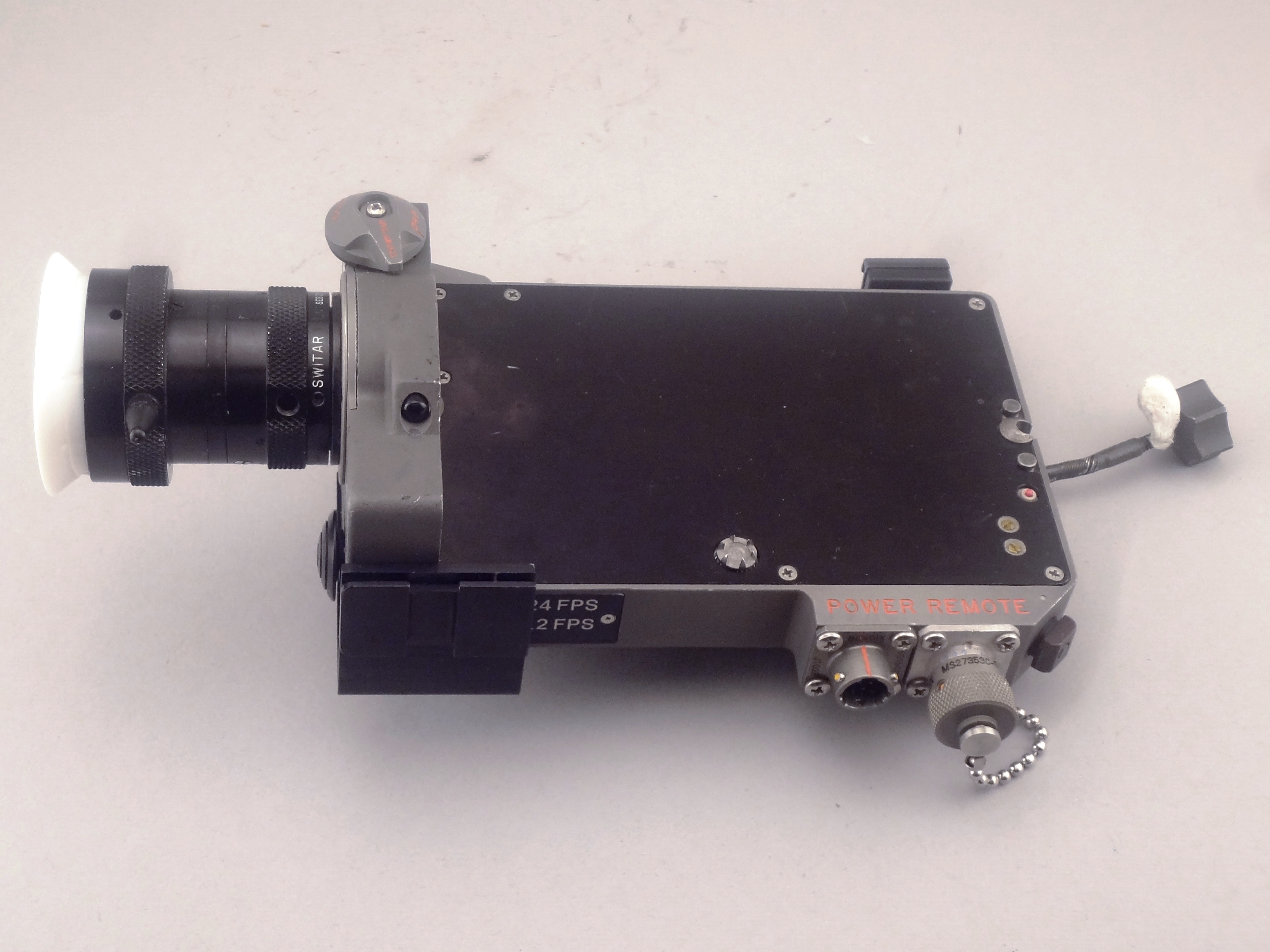
| View of what would be the right side when view from the back of the camera. The DAC was mounted on brackets at either of two locations for views through the LMP's window of the final approach to landing, Neil's climb down the ladder, EVA activities in the camera field-of-view, and the ascent. A labeled version of Apollo 11 photo AS11-36-5389 shows the camera as mounted on the crash bar where Buzz placed it during the initial LM inspection. This is the location from which the descent and landing would be filmed. Before any filming, a magazine was attached to the left side, which is hidden from view in the photo above. There is no magazine attached in any of this series of images. The large, flat, black button on the front surface below the lens starts and stops filming. The black, L-shaped fitting (with a silver-color tightening knob) on the camera's right side is the right angle bracket. A portion of the vertical piece folded unto the bottom mates with a Utility Bracket Assembly for filming out the LMP window during the descent. Lotzmann photograph. (Click on the image for a larger version) |
Additional Lotzmann Photos
(Click on the images for larger versions)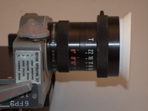 |
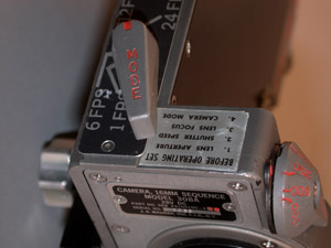 |
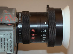
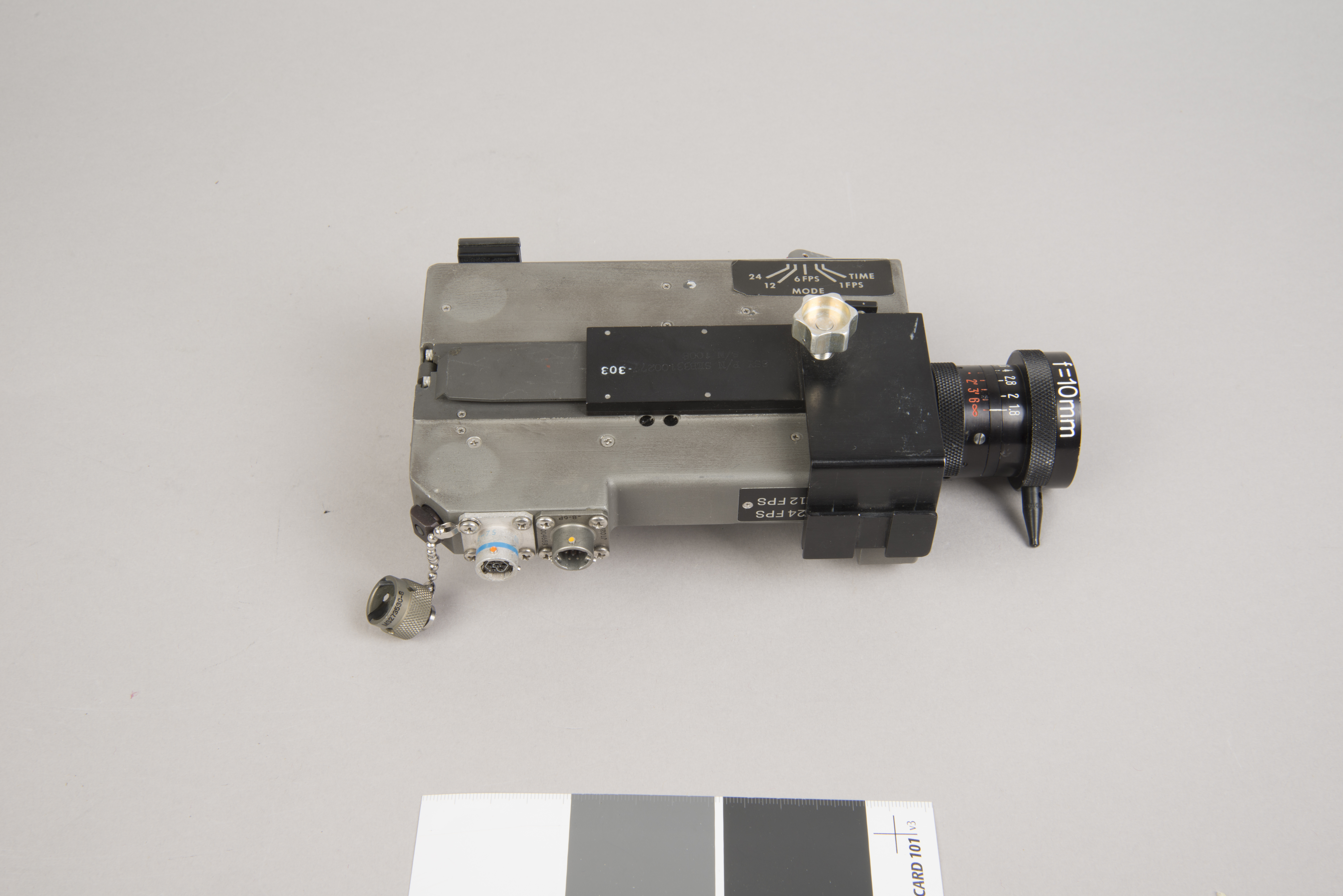
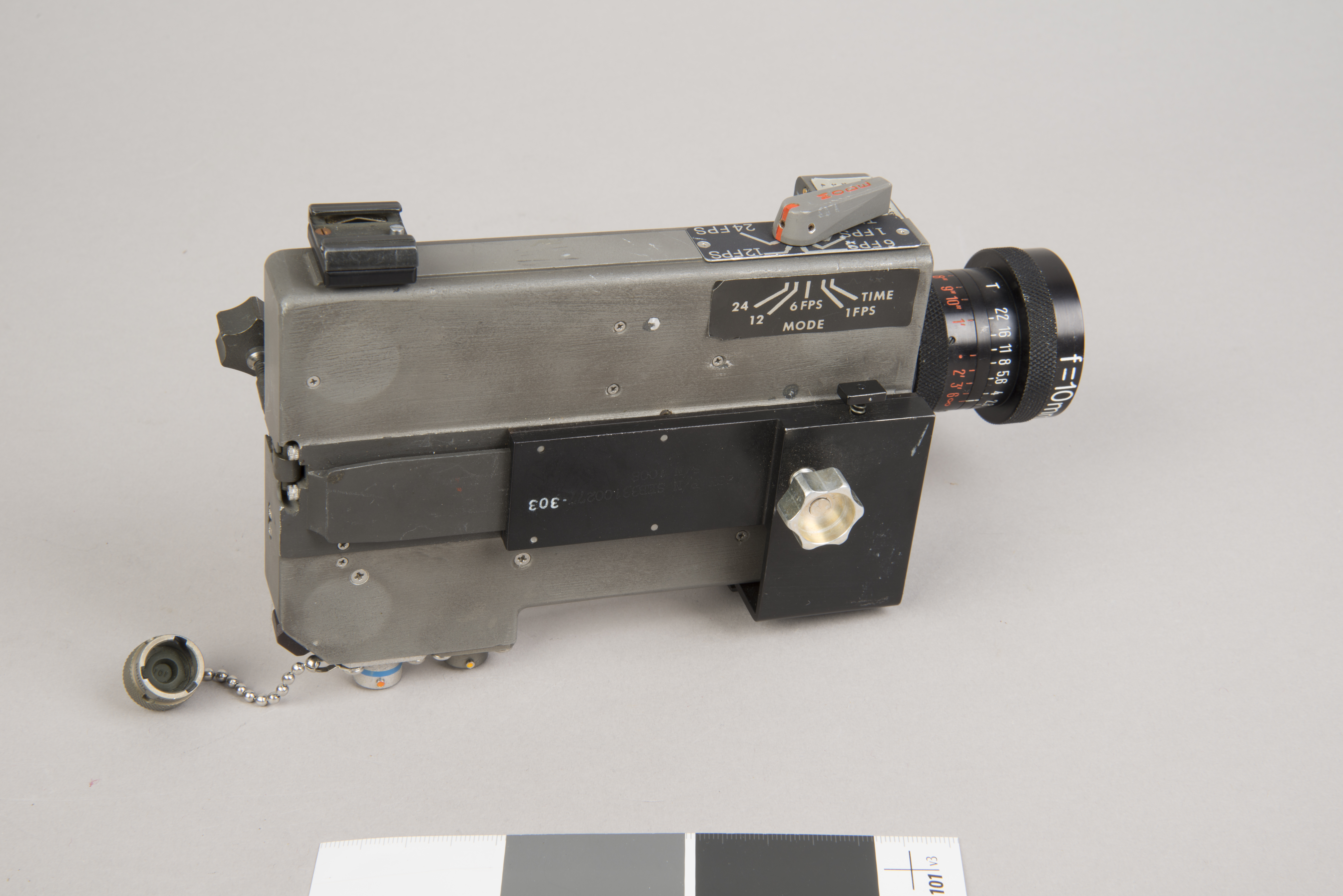
| Close-up of the lens barrel and procedures decal. An exposure selector is above the decal. | Close-up of procedures decal and mode switch. |
 |
 |
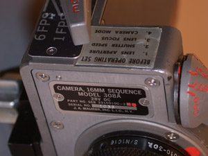
| Close-up of J. R. Maurer tag | Close-up of lens barrel |
NASM Conservation Photographs
 |
 |
 |
 |
 |
 |
| Note that the Teflon Lens Shade had been
removed sometime before these photos were taken.
Detailed descriptions of the DAC and its components can be
found in an excerpt
from the Handbook
of Pilot Operational Equipment (NASA Johnson 1973). |
Lotzmann Photos of the Lens
 |
 |
 |
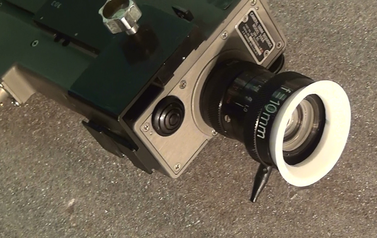
| The illustration in the
center shows the configuration of the lens as flown -
without the shade. "Sturdy tabs are
provided on the aperture and focus rings to assist in
setting and in lens installation and removal
(when wearing gloves)." When the camera was returned to
Earth, the focus tab was missing. One
possible explanation is that, while filming Neil's
egress, Buzz had to change the setting for the
aperture. While doing this, he accidentally
touched the tab of the focus ring, with the result that
the rest of the footage on this magazine was
blurred. Later, he may have removed the focus tab
to prevent a recurrence. Ulli notes that,
when examining the camera at the Garber facility,
"I saw no sign that the missing tab had broken off."
(Click on the images for larger versions.) |
Return to Collection Image
Return to Apollo 11 Lunar Surface Journal
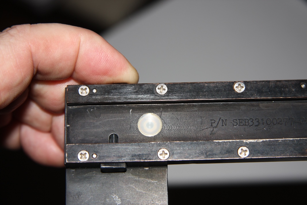
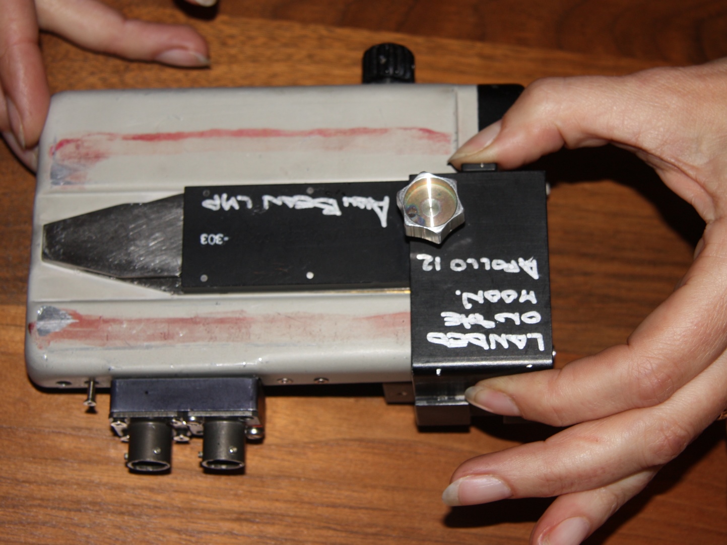
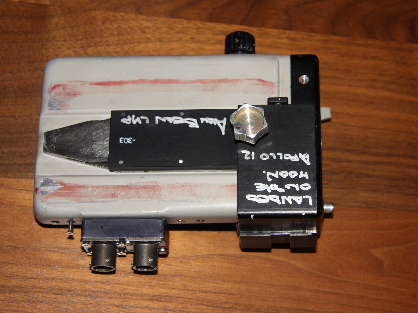
Right-Angle Bracket
(Photos of an item not in the Smithsonian collection nor among the
Armstrong material)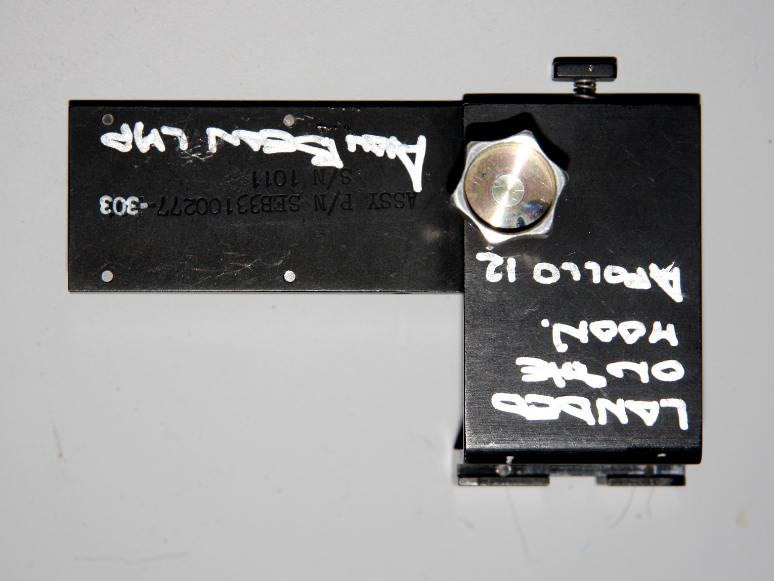 |
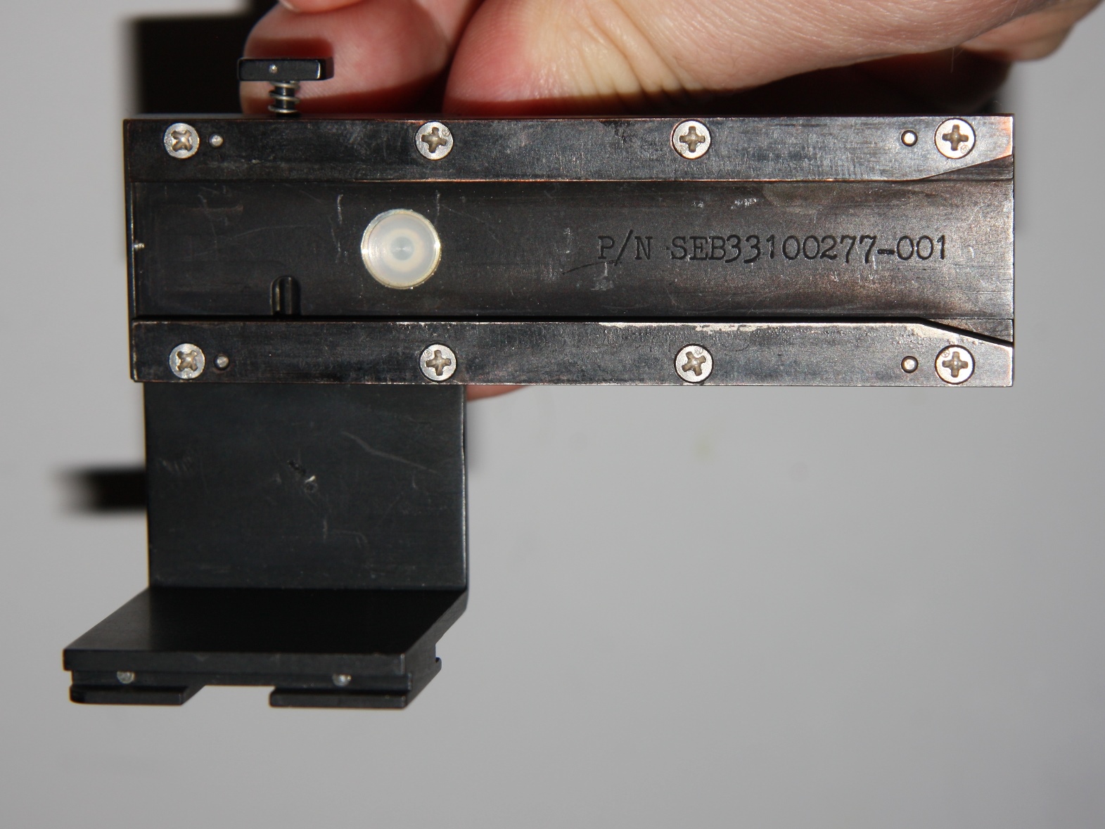 |
| (Left) Flown Apollo 12
Right-Angle Bracket with silver-colored thumbscrew;
(Right) bracket left-right reversed. With
the button on the top in it's current 'out' position,
the bracket would be secured to the camera after
installation. (Click on the images for larger versions.) |
 |
 |
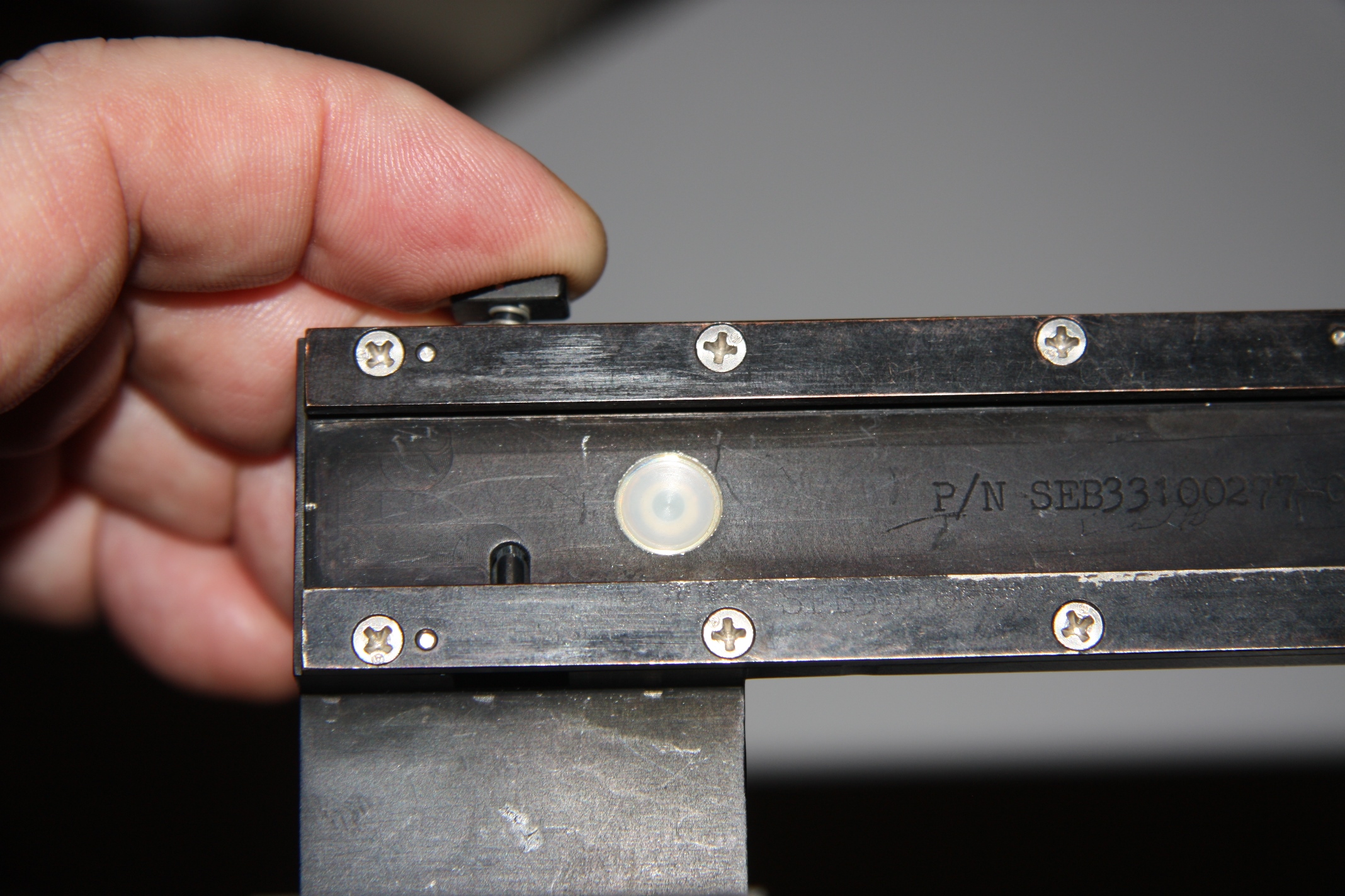
| (Left) Prepared to
depress button; (Right) button depressed and securing
catch moved out of female fitting. (Click on the images
for larger versions.) |
Return to Collection Image
Return to Apollo 11 Lunar Surface Journal
Mating Right-Angle Bracket with DAC
(Photos of items not in the Smithsonian Collection)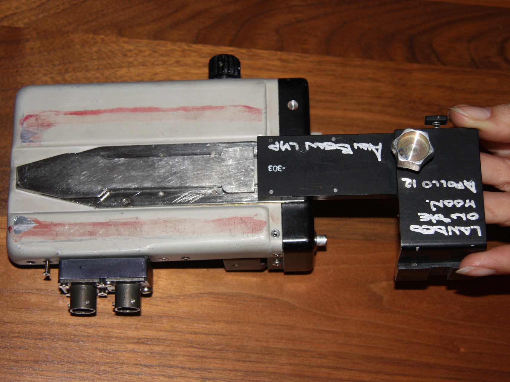 |
 |
 |
 |
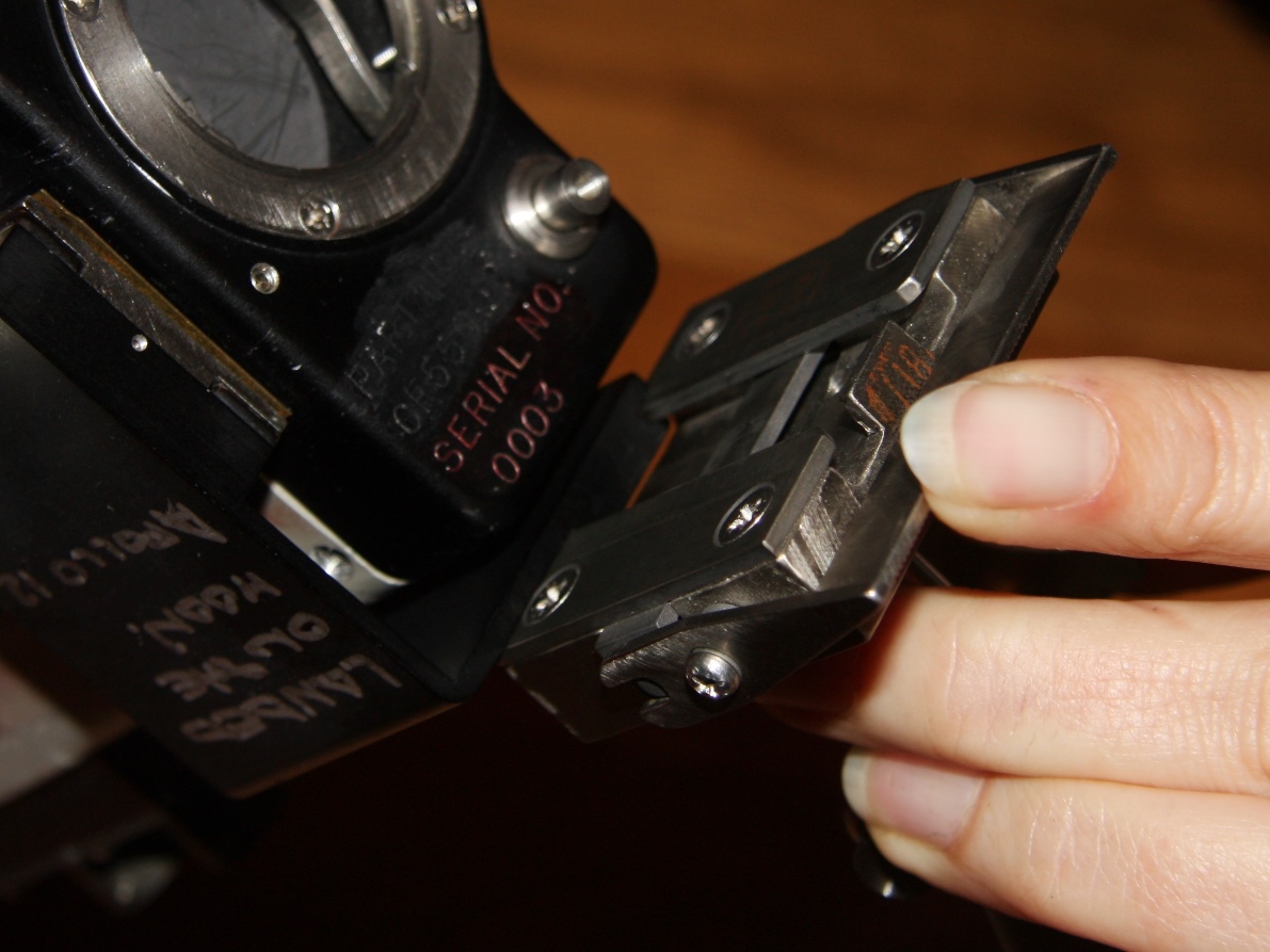
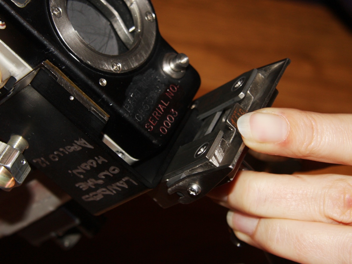
| In this set of four
frames, the right-angle bracket is mated to a broken,
Gemini-era DAC which, among other faults, does not have
a lens which would be on the right of a complete
DAC. (Upper left) Right-angle bracket positioned
on right end of the male fitting on the DAC. (Upper
right) With the disengagement button depressed, the
bracket is moved aft. (Lower left) Bracket in final
location. (Lower right) Tightening knob turned.
During installation on board the LM, the right-angle
bracket would already be mated with a Utility Bracket
which, in turn, was already clamped onto the crash bar
across the LMP window. With the right angle
bracket in a fixed position, the front end of the male
fitting on the DAC would have been positioned on the aft
end of the female fitting on the right-angle bracket
and, with the disengagement button depressed, the camera
body would have been moved forward, toward the window.
(Click on the images for larger versions.) |
Return to Collection Image
Return to Apollo 11 Lunar Surface Journal
Mating Right-Angle Bracket with a Utility Bracket
(Photos of items not in the Smithsonian Collection)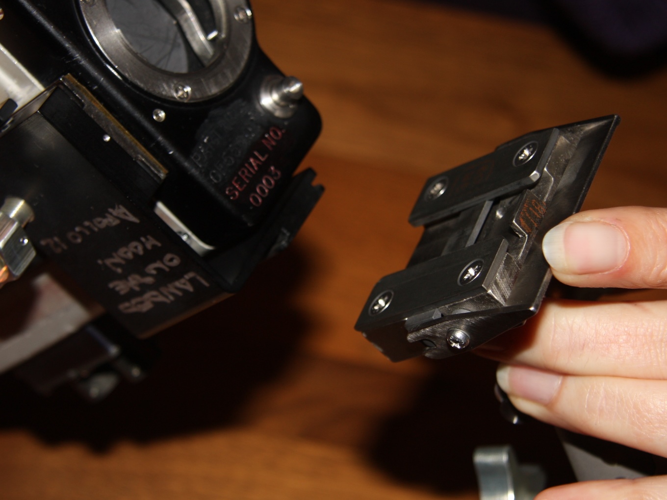 |
 |
 |
 |
| Fitting a Utility bracket
to the portion of the Right-Angle Bracket on the Bottom
of the camera below the lens. (Upper left) Utility
bracket with rocker in the engaged position. Note
that fixed stopper plate is above the installer's
forefinger. The stopper plate ensures that the two
fixtures at the correct relative locations so that
release of the rocker arm will result in a firm
connection between the brackets. (Upper right) the
two brackets are in the right relative positions.
Rocker arm has not been pushed up to lower the
engagement plate. (Lower left) Rocker arm has been
pushed up to the disengagement position so the two
brackets can be pushed together. (Lower right) Mating
nearly complete although the rocker arm has not been
released. (Click on the images for larger
versions.) |
DAC / Right Angle Bracket / Utility Bracket Assembled
(Click on the image for a larger version.)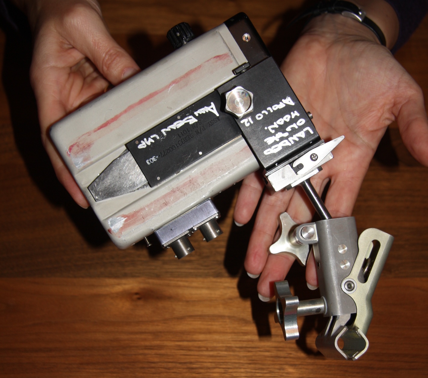
Return to Collection Image
Buzz Installs Brackets for two DAC locations
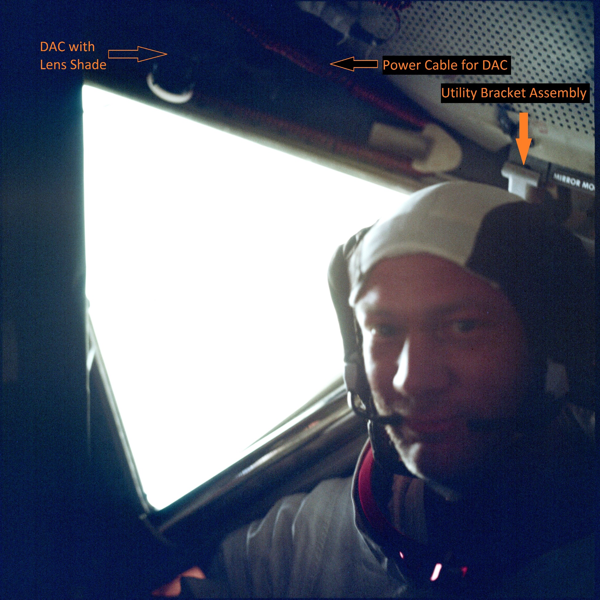
| During the initial LM inspection during the
trip out from Earth, Buzz installed Utility Brackets at
two locations where the DAC would be mounted for filming
(1) Neil's climb down the ladder and initial
familiarization with moving in lunar gravity; and (2)
filming the final approach and landing. Neil used the
on-board TV to capture Buzz's activities for transmission
to Earth. In the first (44 Mb) of two video clips related to the Utility brackets, Buzz is attaching the clamp end of a bracket at the upper right corner of the LMP window. Once he has the clamp in place and tightened, he loosens the tightening wheel at the bracket end enough that he can properly position the bracket. Once that is oriented, he makes sure both wheels are tight. Next, he gets the DAC from off-camera to the left for attachment to the bracket. He checks that he has the front of the male fitting on the right side of the DAC properly aligned with the female fitting on the bracket. He is holding the camera with his left hand and uses his right hand to help get the mating started and to move the rocker arm to disengage. After some initial difficulty with the alignment, the camera moves forward as the male fitting slides into the female fitting. He then makes fine adjustments of the camera pointing, which he checks by sighting along the camera. He would have done this procedure at least a few times during training. The second clip (32 Mb) starts with Buzz getting the second Utility Bracket out of the Interim Stowage Assembly, which is attached to the Alignment Optical Telescope (AOT) near the ceiling at the front of the cabin. Before Buzz went to the ISA, he had rotated the crash bar up from its stowed position along the right side of the LMP window to its horizontal orientation across the window, latching it on the left side. Returning with the second Utility Bracket, he opened its clamp, fit it around the crash bar and started tightening the thumbscrew. He quickly realized that he needed to turn the bracket assembly 180 degrees. Once he had it attached, he went to the LHSSC (Left Hand Side Stowage Compartments) on the wall next to Neil's station, searching for the right-angle bracket, mostly by feel through the cloth bags. We have removed about 2 minutes 40 seconds from the middle of the clip and start again just before Buzz finds the right-angle bracket. He goes back to to the LMP window and attaches the right-angle bracket to the utility bracket with his right index finger on the disengage button. He has no trouble getting that done and then removes the DAC from the bracket at the upper-right corner of the window. He uses his left fingers to disengage the camera with the rocker arm. The camera slides out easily and then attaches to the right angle bracket without trouble. Labeled details from AS11-37-5531 and 5534, both taken after the EVA, show the DAC in a third location above the upper left corner of the window and, at the upper right corner of the window, the utility bracket Buzz installed for filming Neil's ladder descent. |
Return to Collection Image
Return to Apollo 11 Lunar Surface Journal
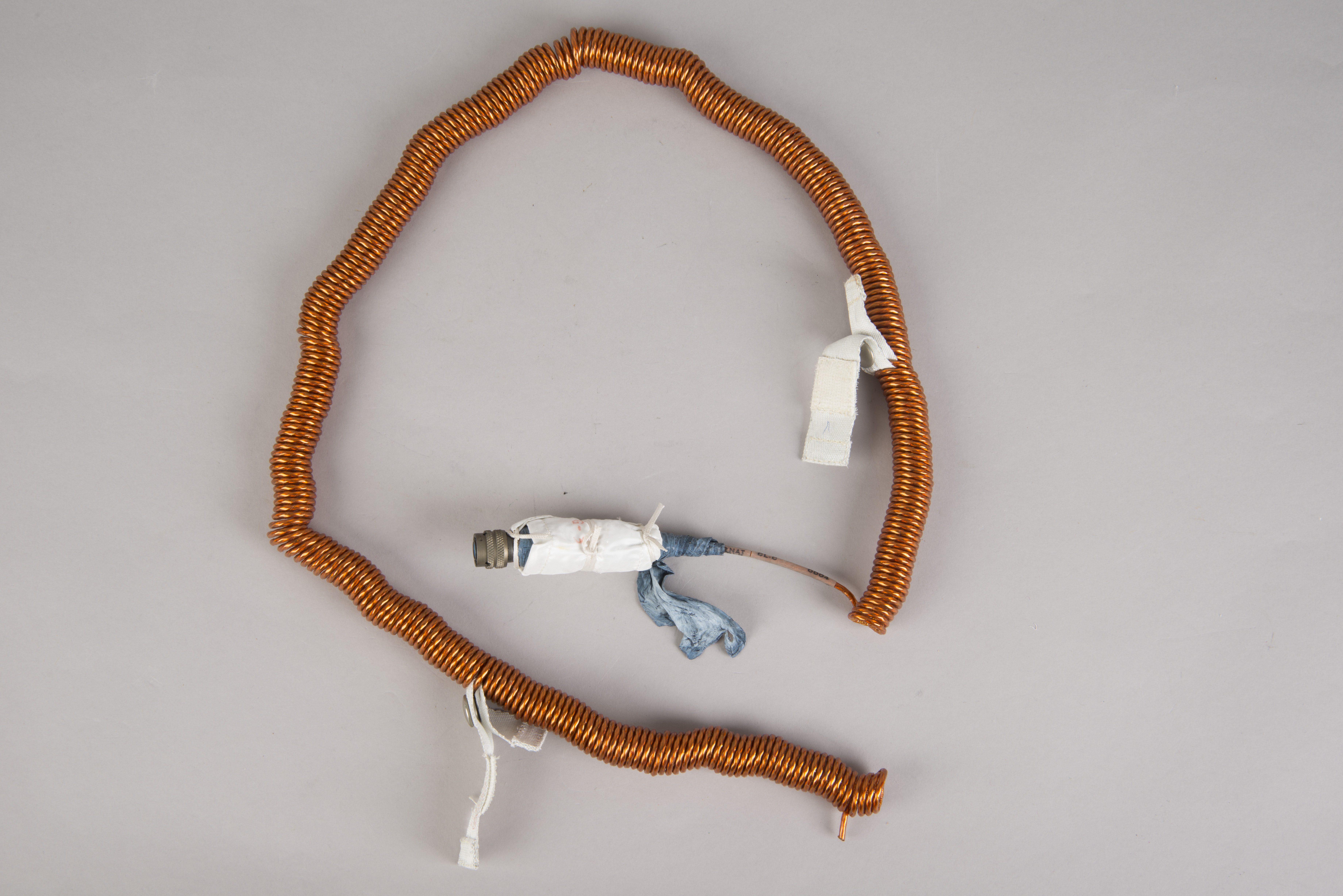
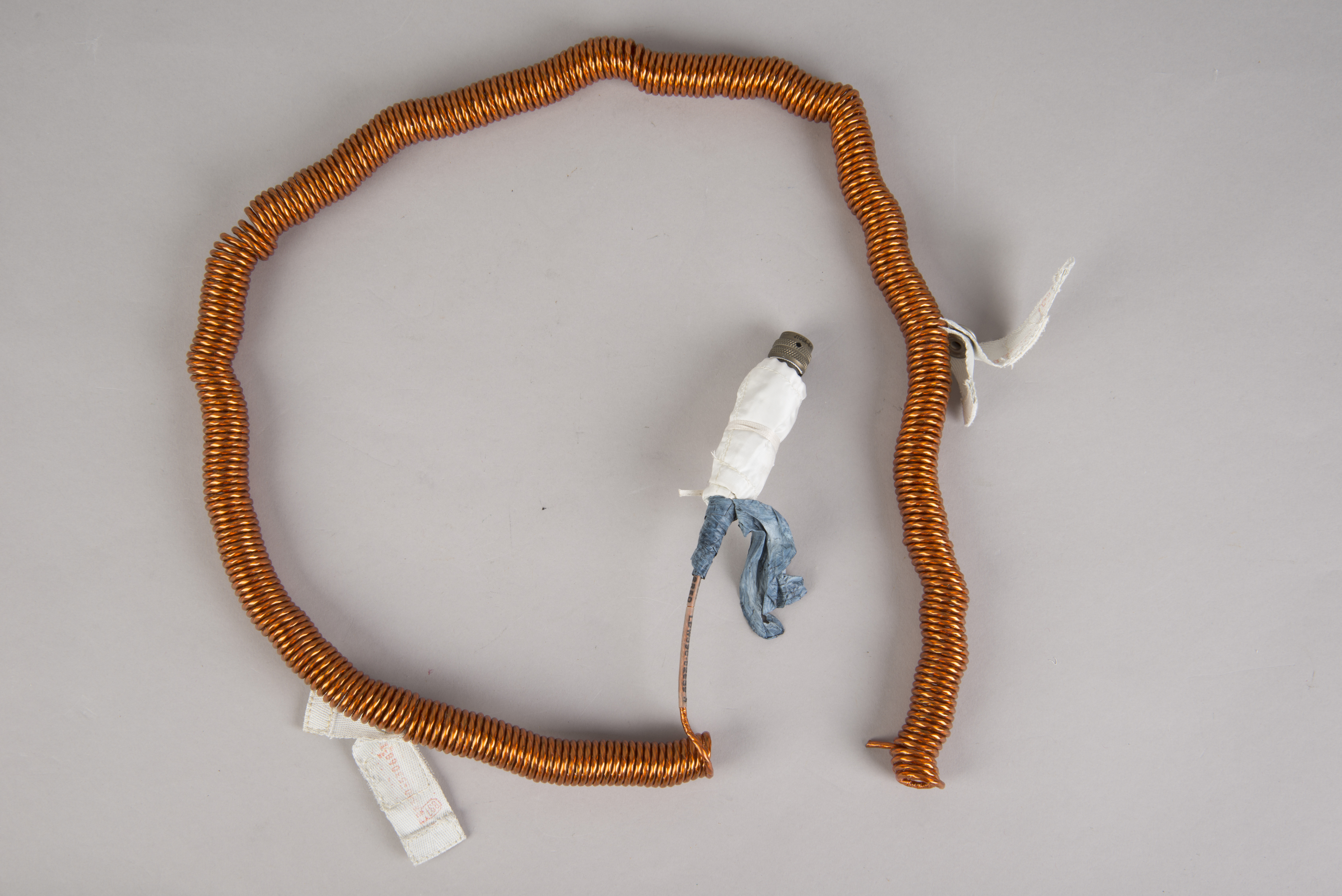
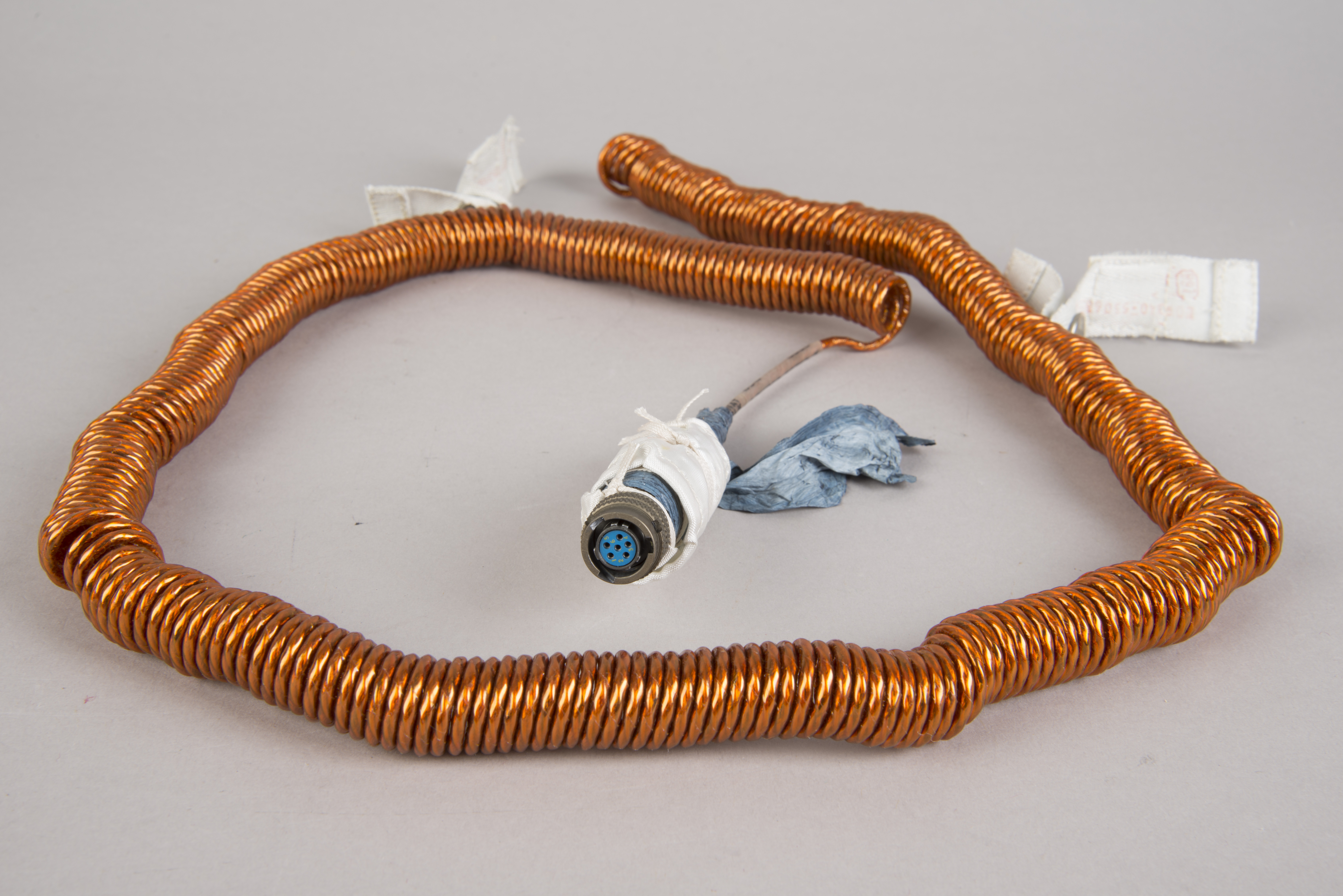
DAC Power Cable
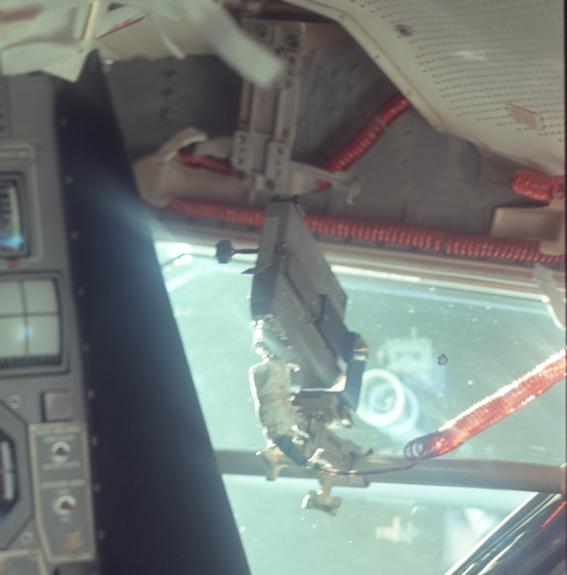
| Detail
from AS11-36-5389,
taken during the initial LM inspection during the trip
out from Earth. The orange-colored electrical
cable is connect to the bottom surface near the back.
(Click on the image for a larger version.) |
NASM Conservation Photographs
 |
 |
 |
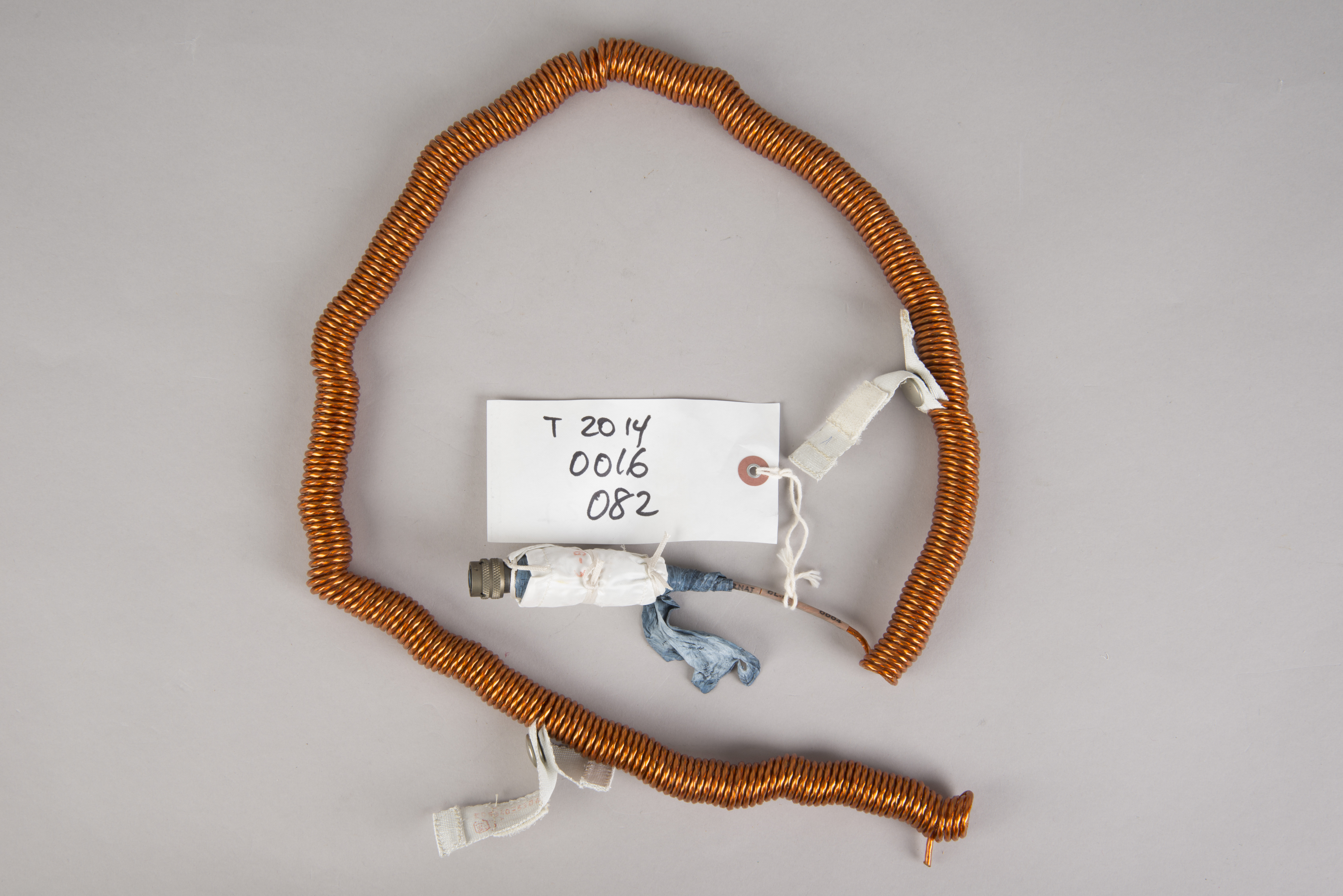 |
| DAC power cable and its
connector. The connector was plugged into the forward receptacle
- labelled "POWER" - on the bottom of the camera. (Click on the images for larger versions.) |
Lotzmann Photographs
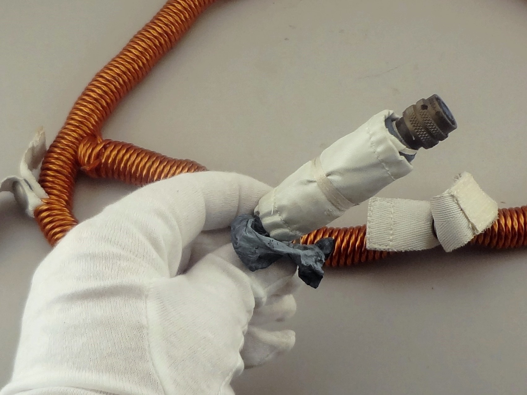 |
 |
| DAC power cable connector
close-ups. (Click on the images for larger
versions.) |
Return to Collection Image
Return to
Apollo 11 Lunar Surface Journal
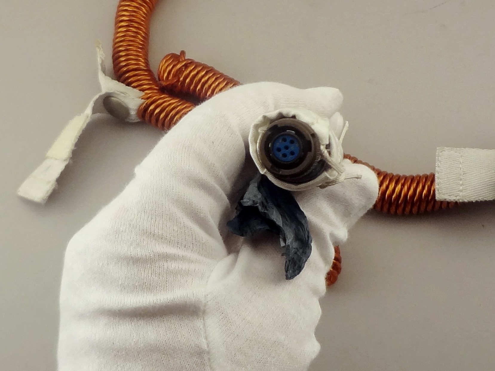
Lens Shade (Teflon) for DAC 10-mm Lens
NASM Conservation Photographs
Lotzmann Photo at Lower Right
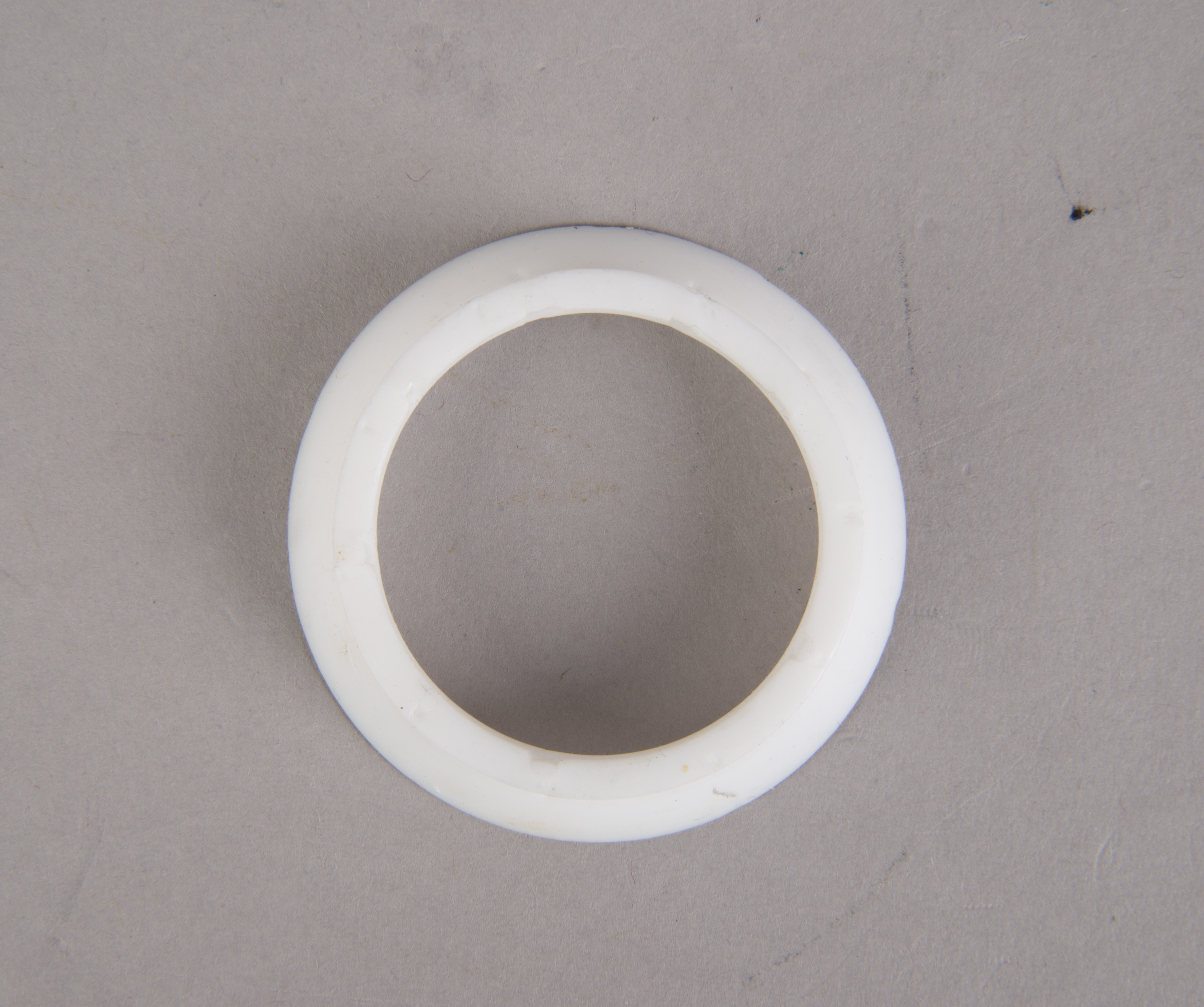 |
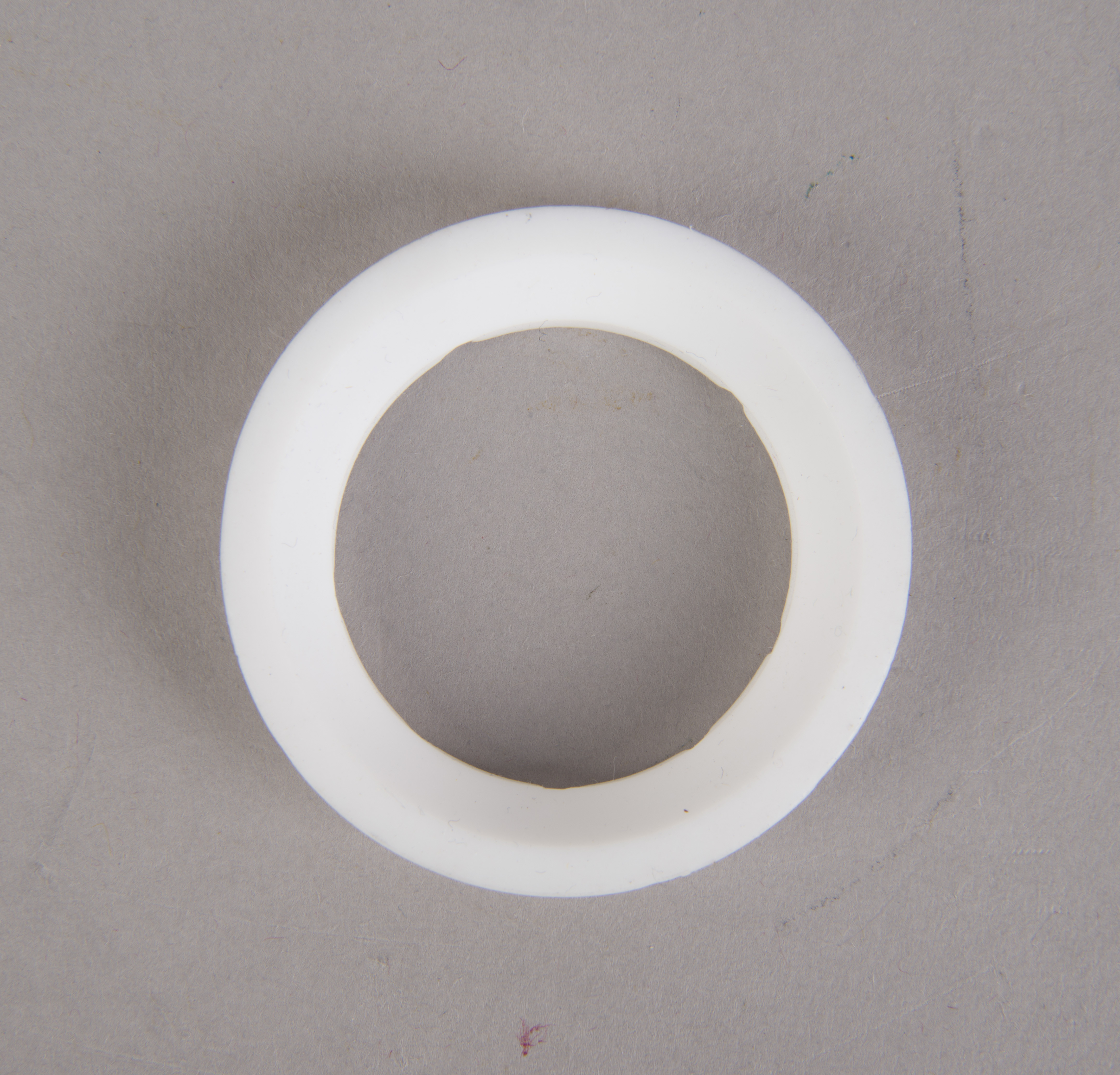 |
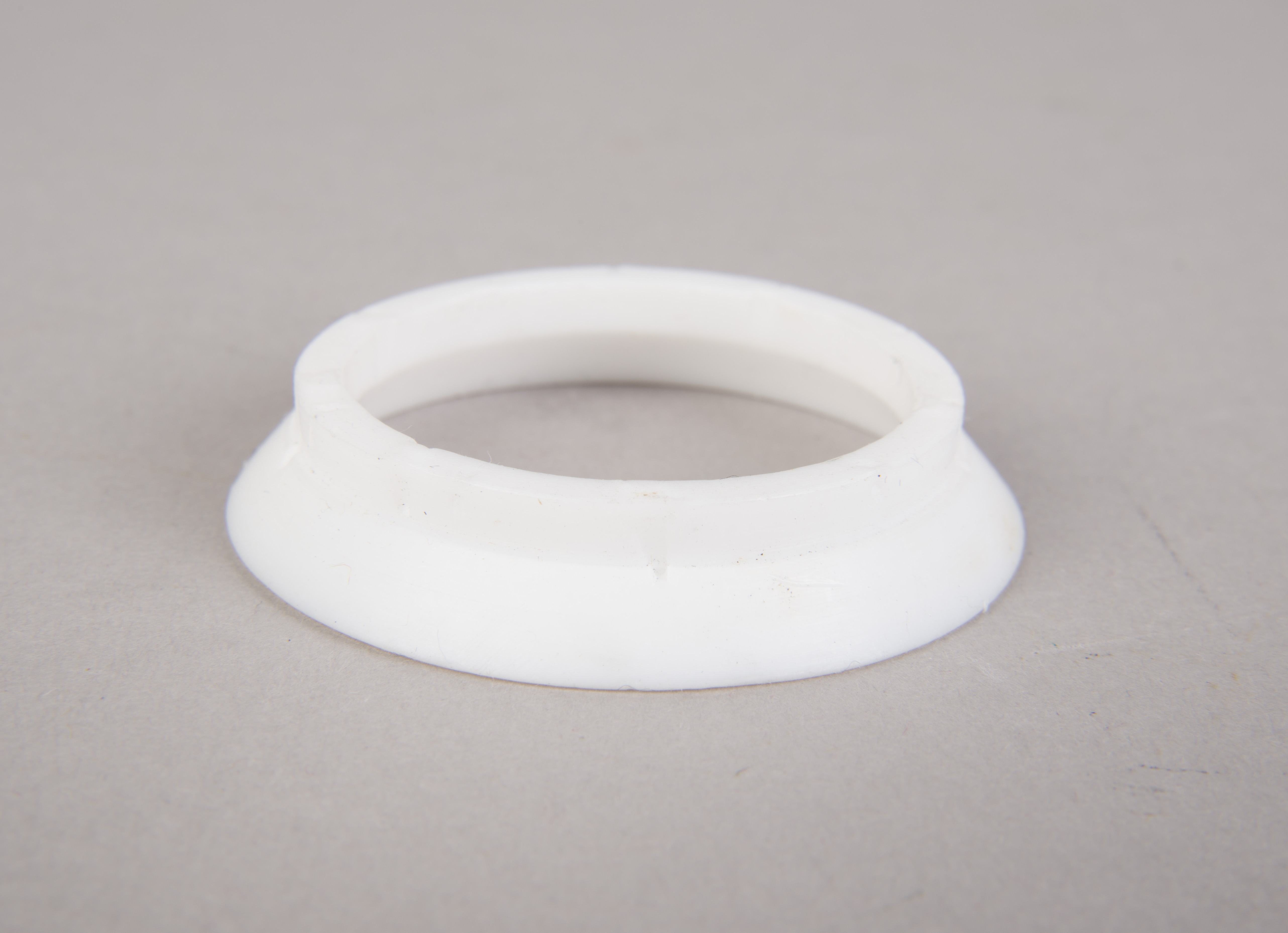 |
 |
| As indicated in a table
in an excerpt
from the Handbook
of Pilot Operational Equipment (NASA
Johnson 1973), only 10-mm lens intended for use in the
LM cabin was provided with this lens shade. The
Command Module and Lunar Surface (EVA) 10-mm lens were
not. The shade may have been flown to protect the
LM window while the camera was being mounted near the
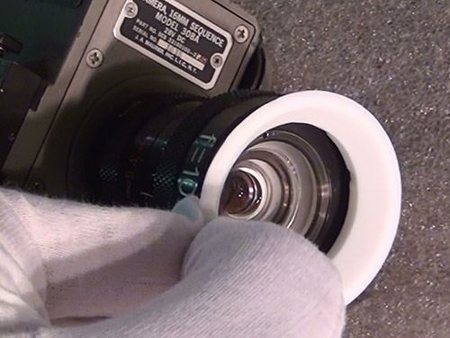
window. The image at the lower right shows
Lotzmann removing the lens shade from the DAC. (Click on
the images for larger versions.) |
Return to Collection Image
Return to
Apollo 11 Lunar Surface Journal
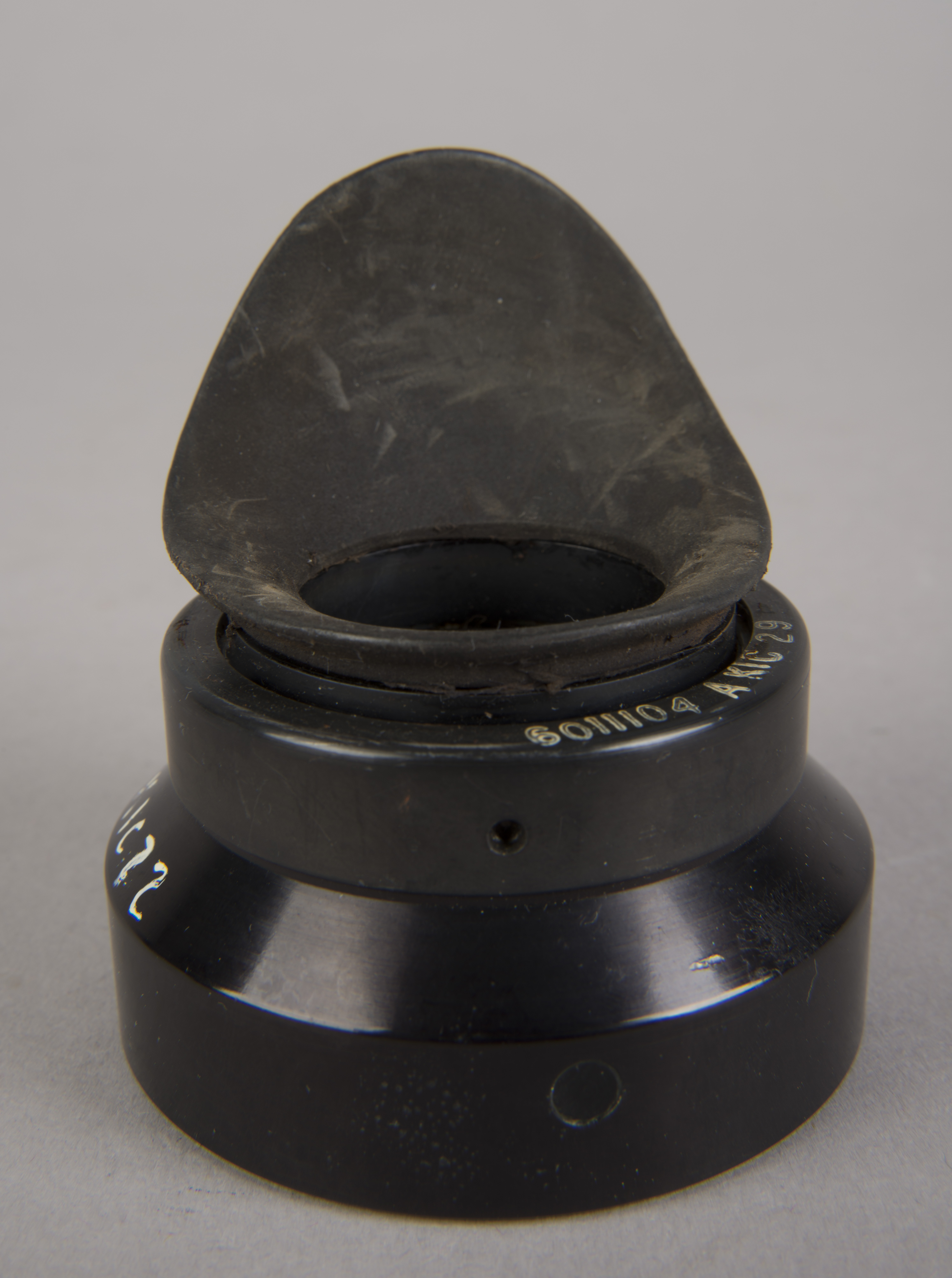
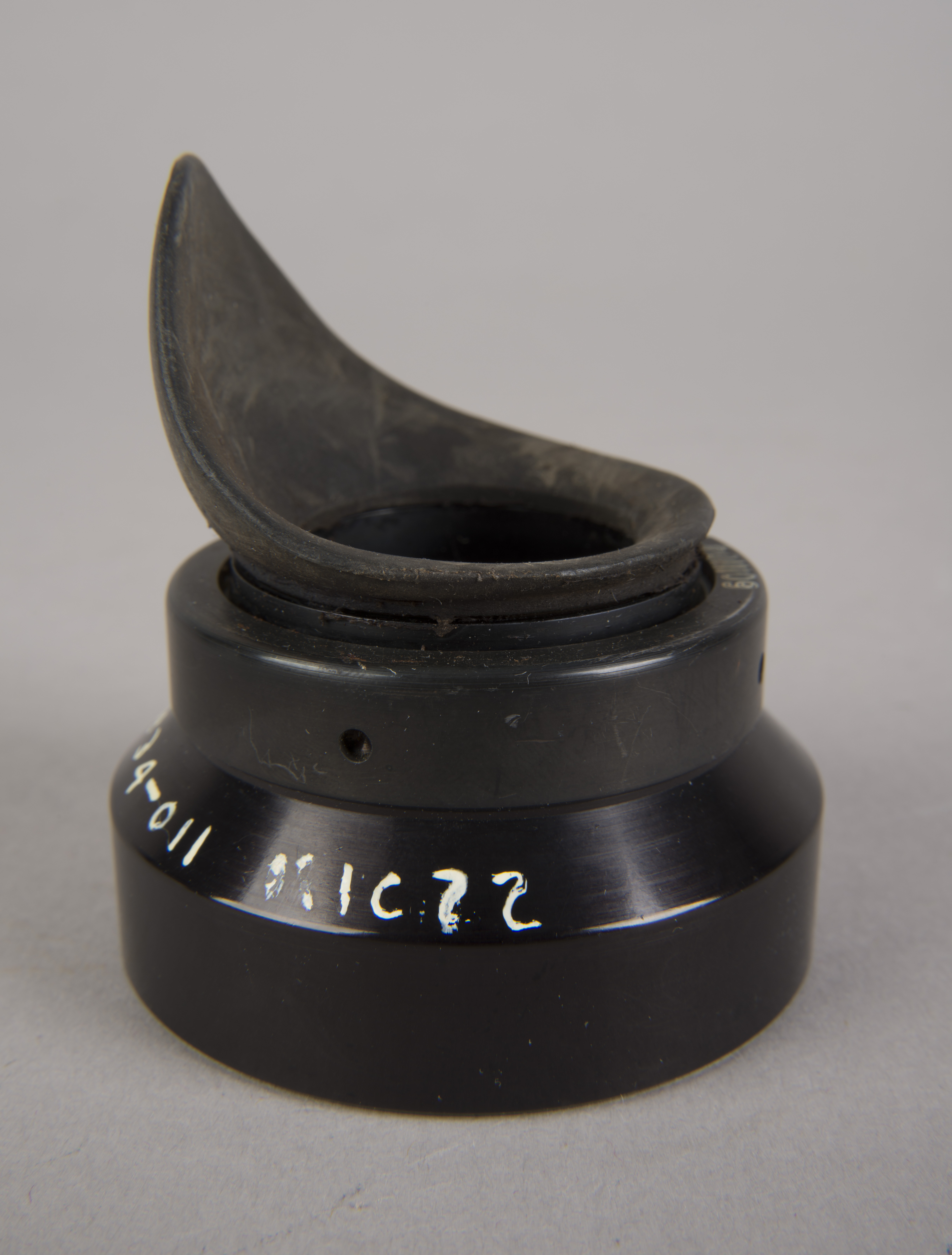
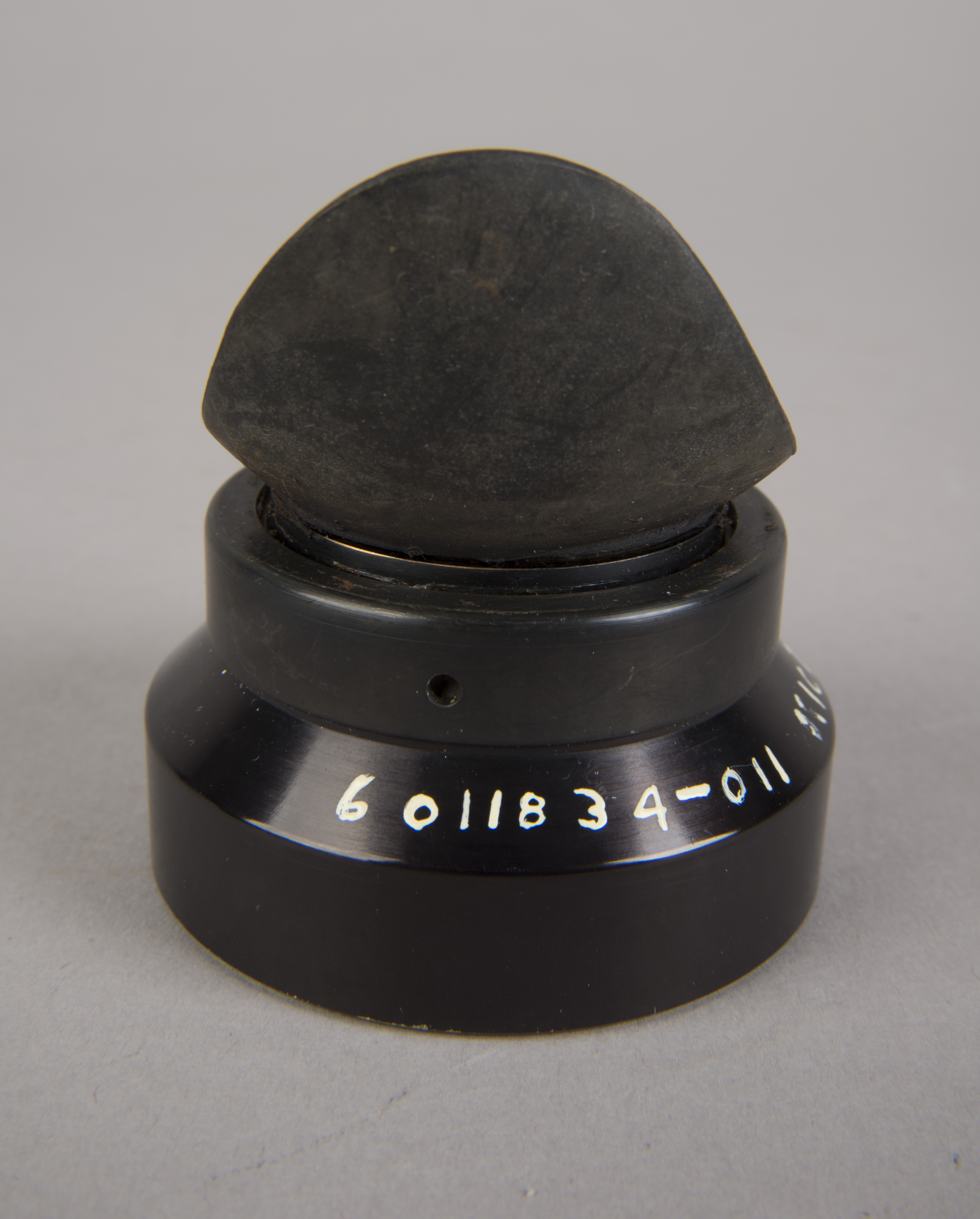
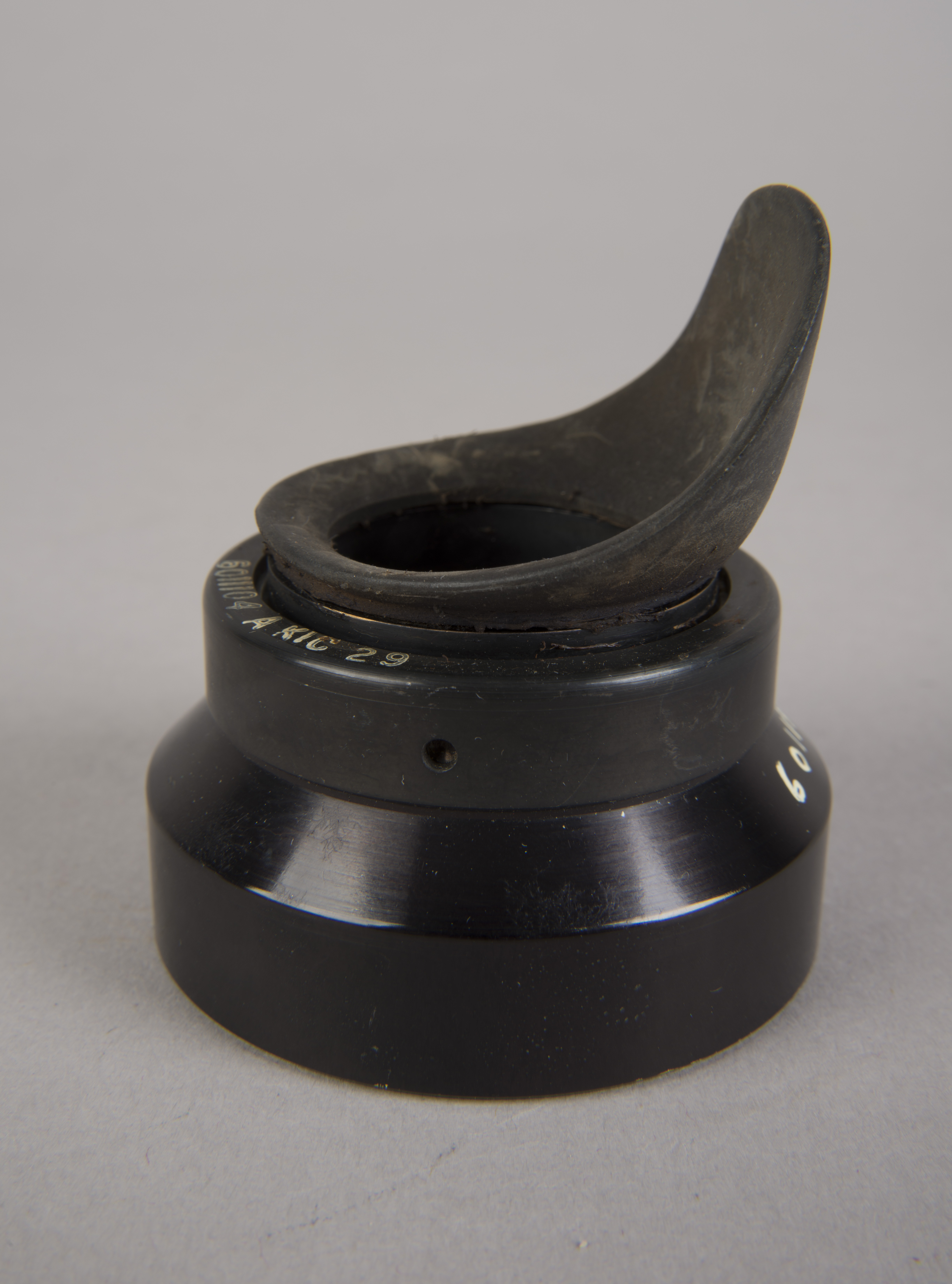
AOT Eyeguard Assembly
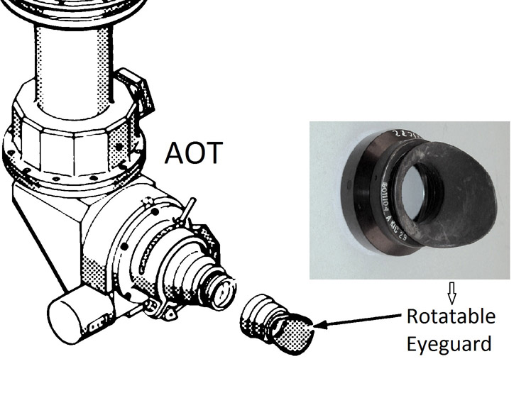
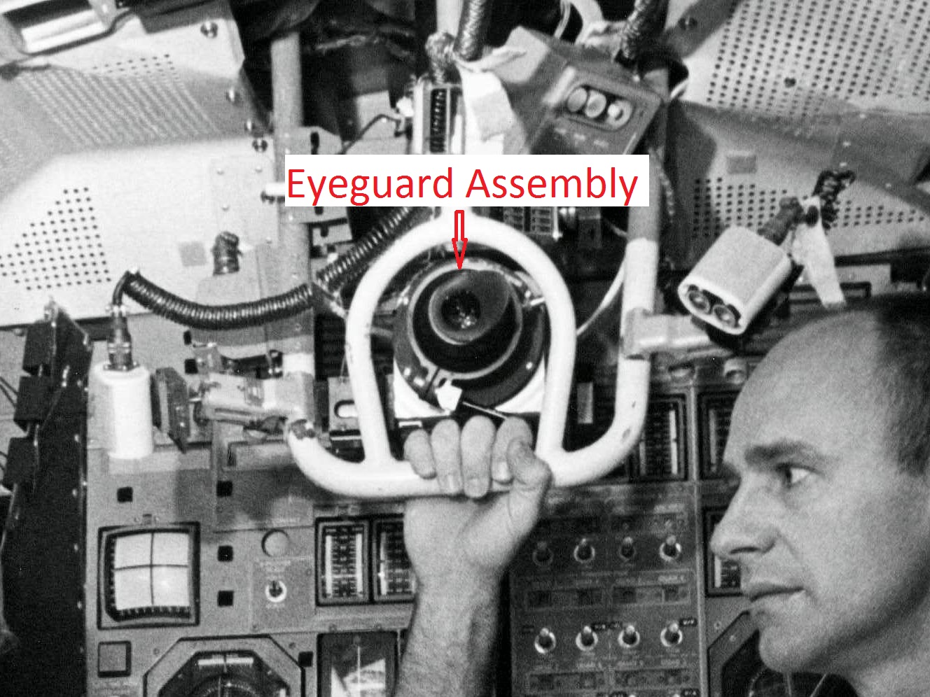
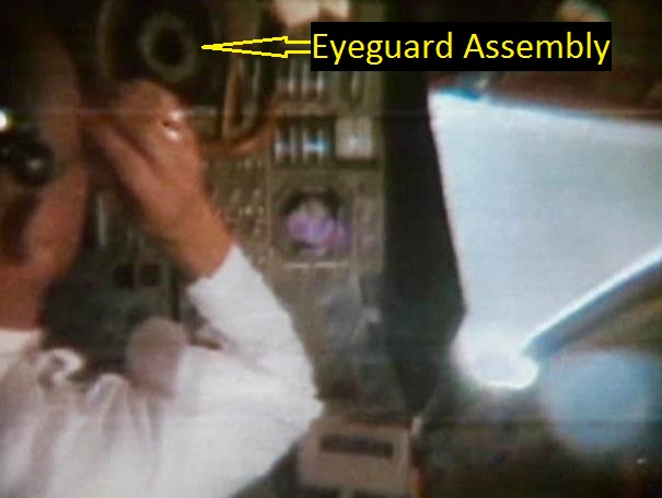
| The assembly consisted of a threaded base which screwed on to AOT barrel and a soft, rubber-like eyeguard. A detail from Apollo 12 training photograph 69-H-1679 shows a training unit in a LM simulator. A frame from the TV Neil shot during the initial LM inspection shows the assembly after Buzz attached it to the AOT. During the flight out from Earth, the Eyeguard Assembly was stowed in the RHSSC (Right-Hand-Side Stowage Compartment) next to Buzz's flight station. |
Lotzmann Photo
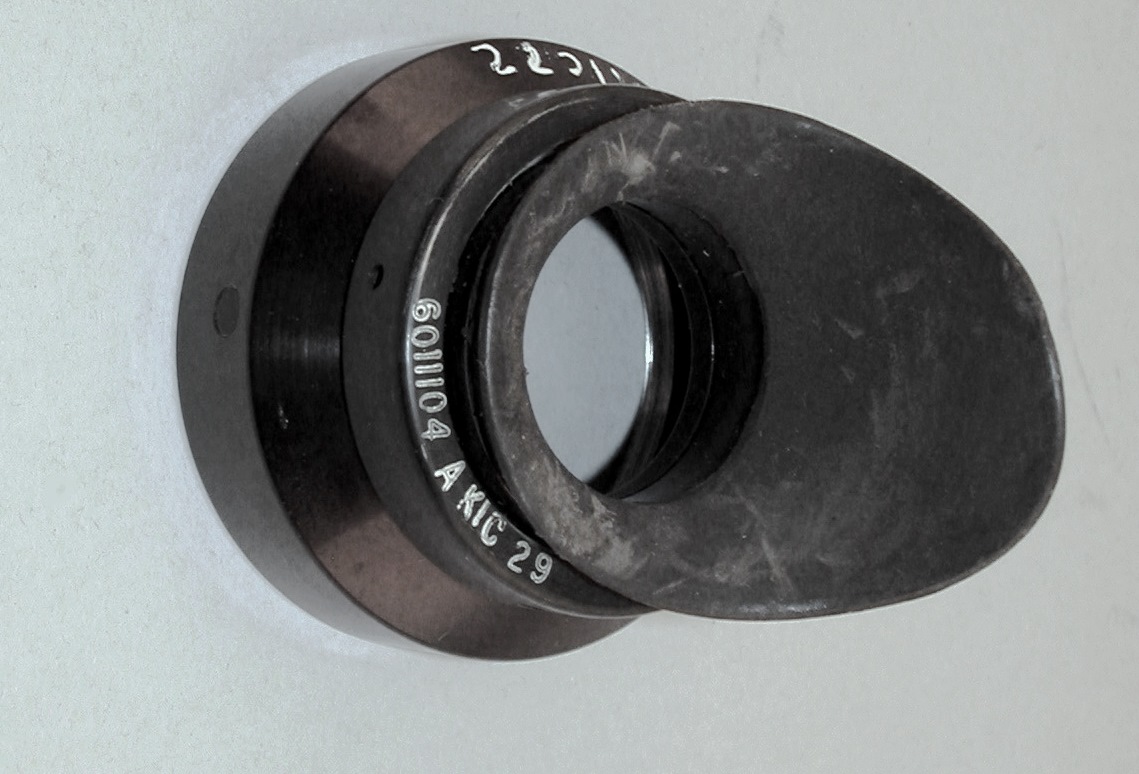
| Apollo 11 AOT Eyeguard
Assembly. Part number 6011104 A KIC 29 refers to
the rubber eyeguard. KIC stands for Kollmans
Instrument Corporation, which was responsible for design
and manufacture under technical supervision from MIT
Instrumentation Lab. Lotzmann photo. |
NASM Conservation Photographs
(Click on the images for larger versions)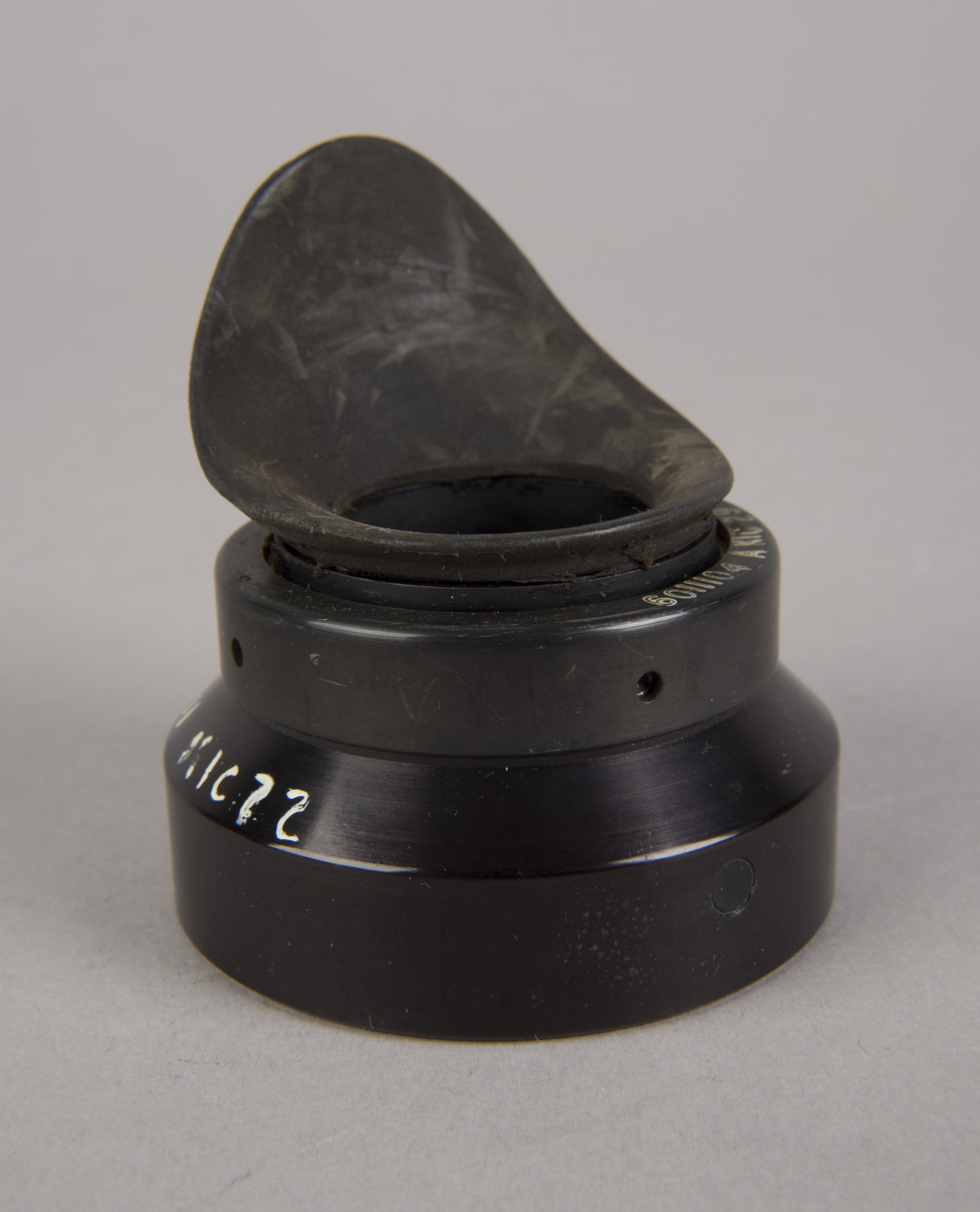 |
 |
 |
 |
 |
 |
| Apollo 11 Eyeguard
Assembly. The view at the lower right shows the threaded
end that screws onto the AOT. Note that there are
no optical elements in the assembly. Part number
6011834-011 KIC 22 applies to the solid base of the
assembly. (Click on the images for larger versions.) |
| Lotzmann photograph of
threaded end, taken at the Garber Facility. (Click on the image for a larger version.) |
Return to Collection Image
Return to Apollo 11 Lunar Surface Journal
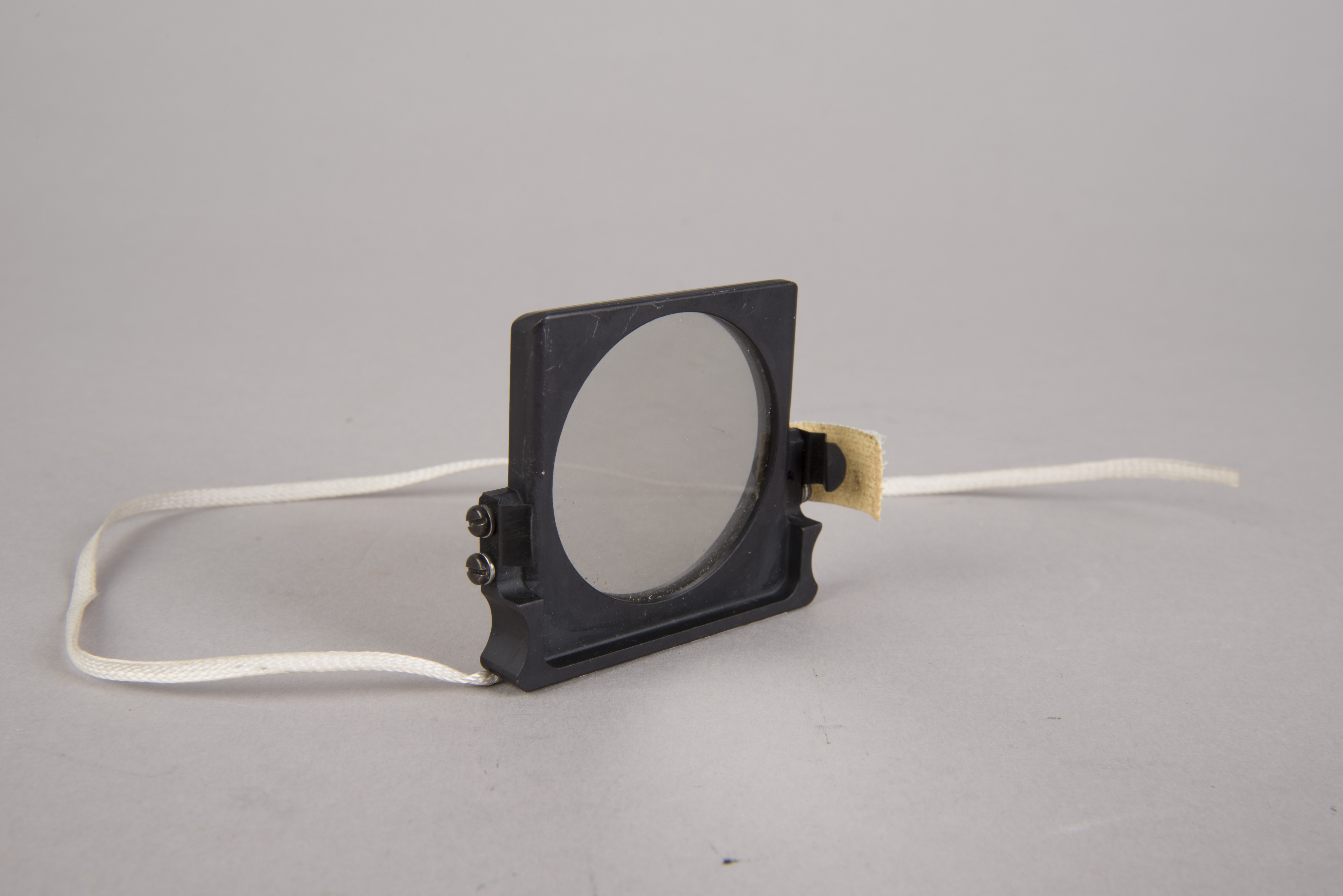
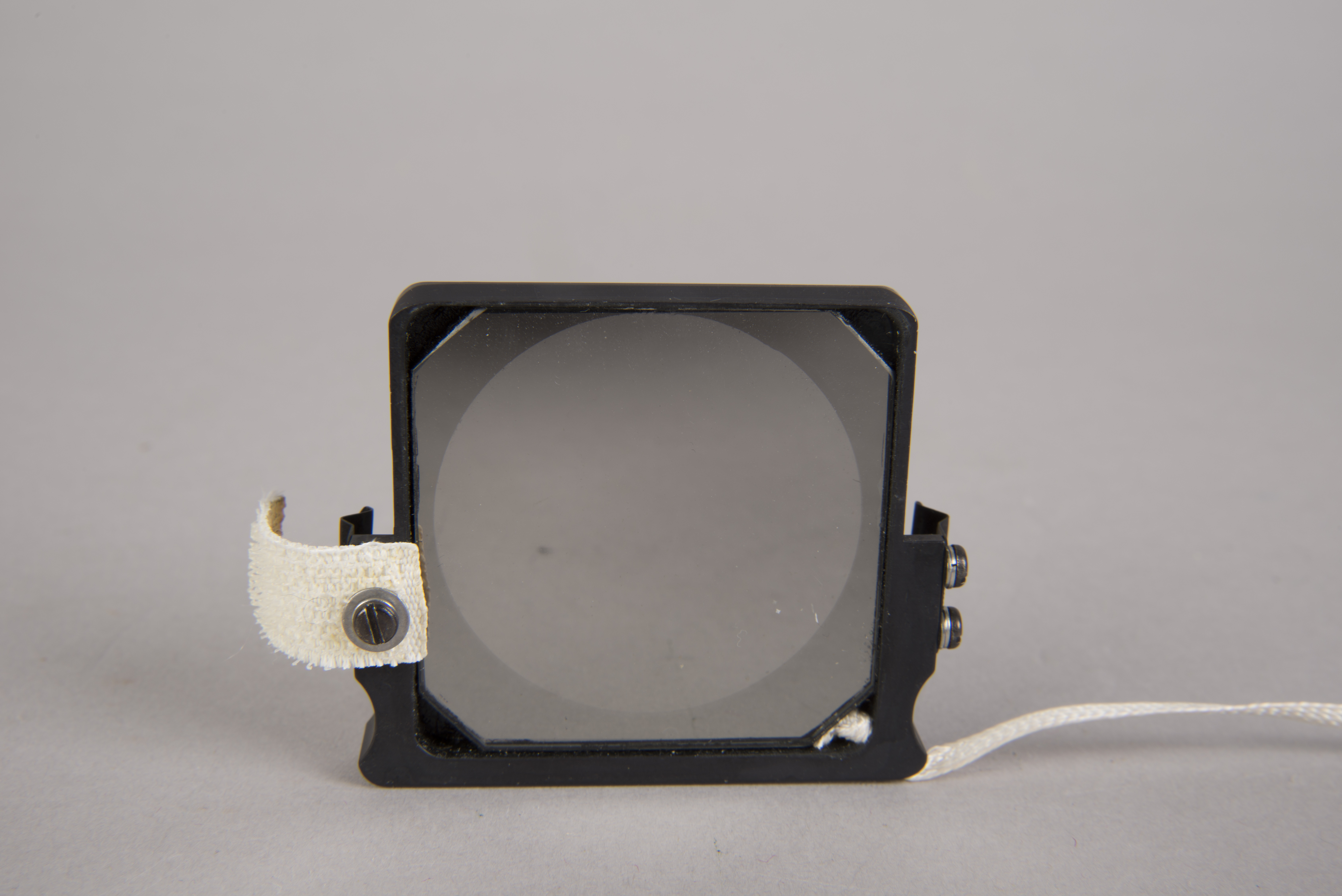
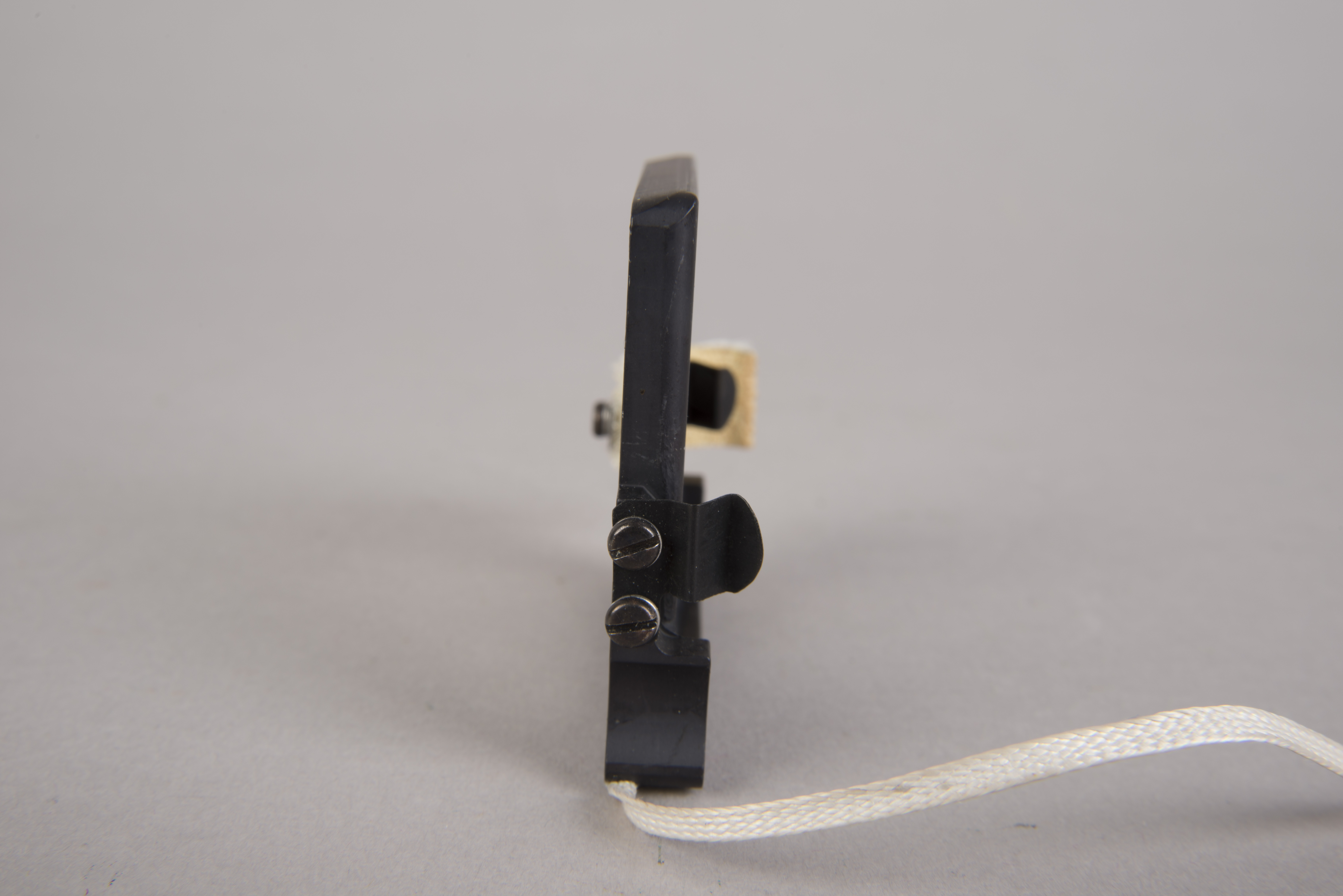
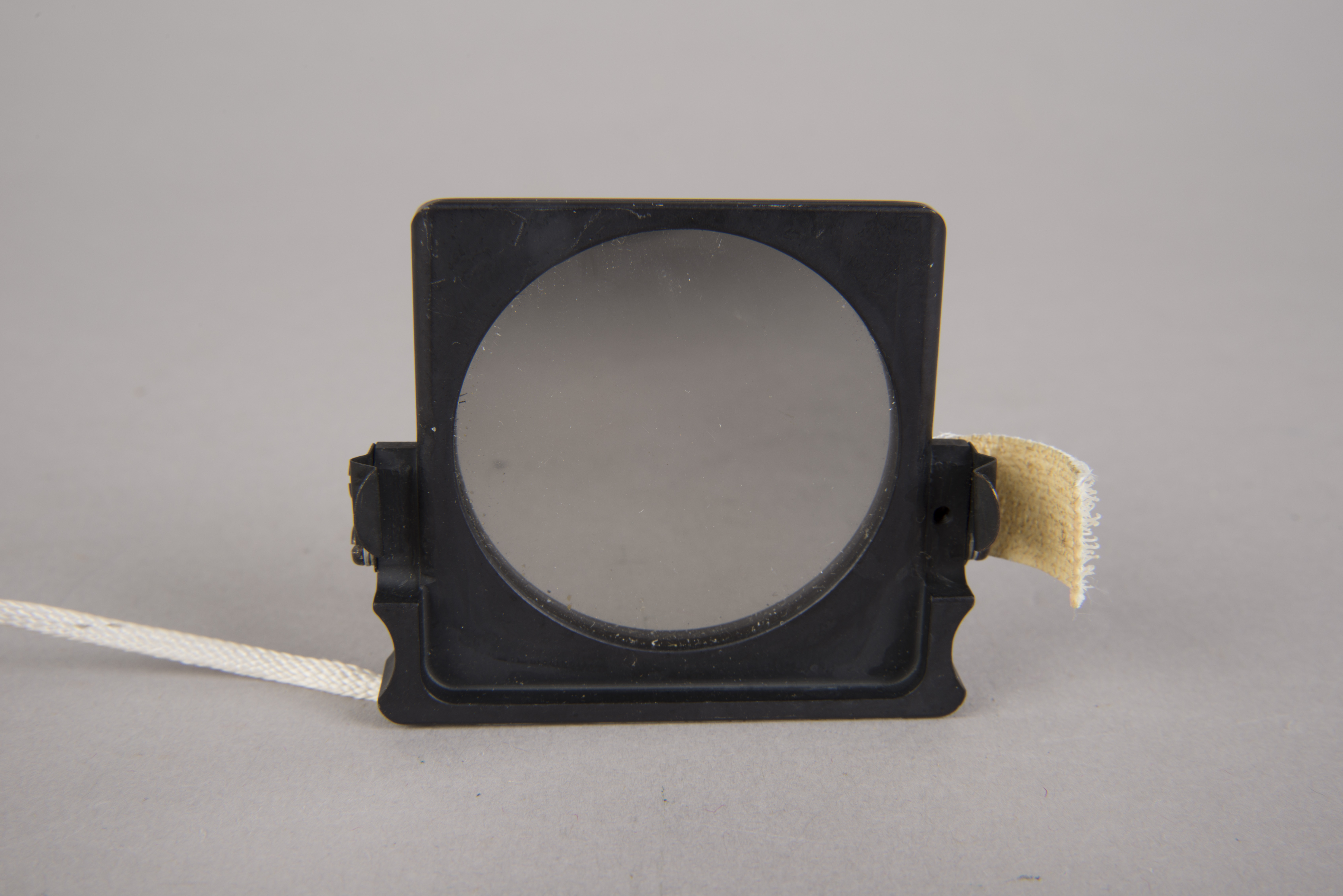
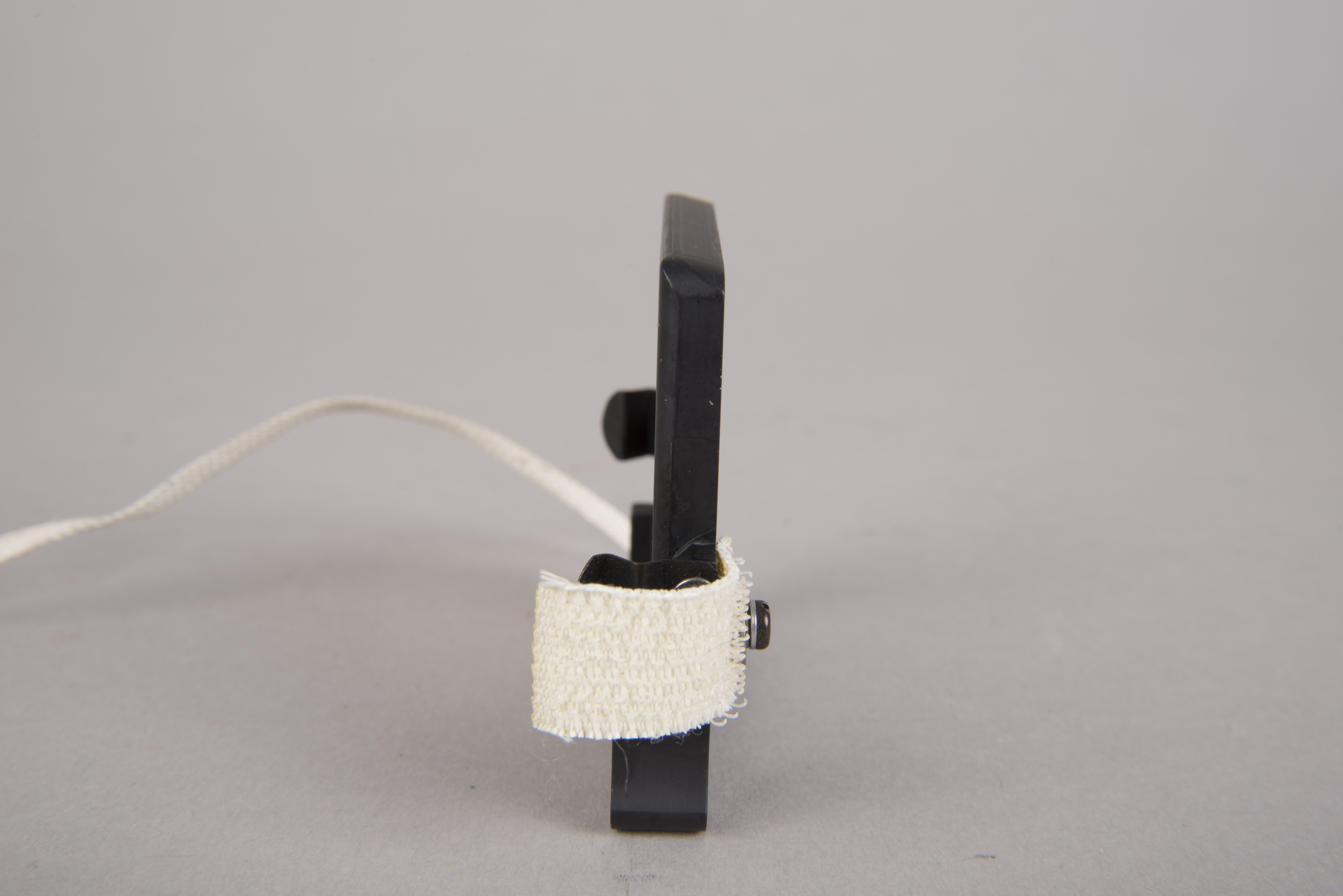
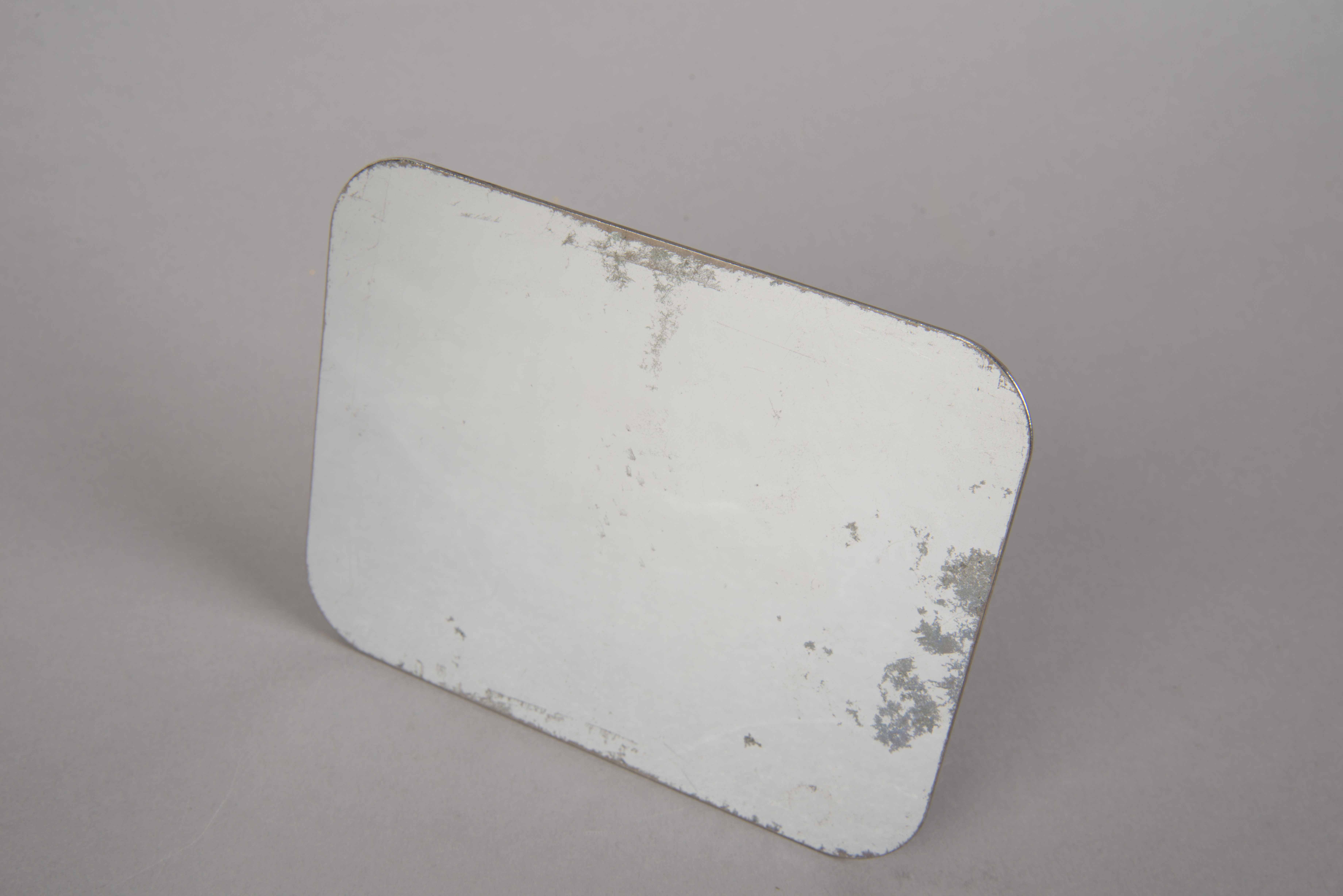
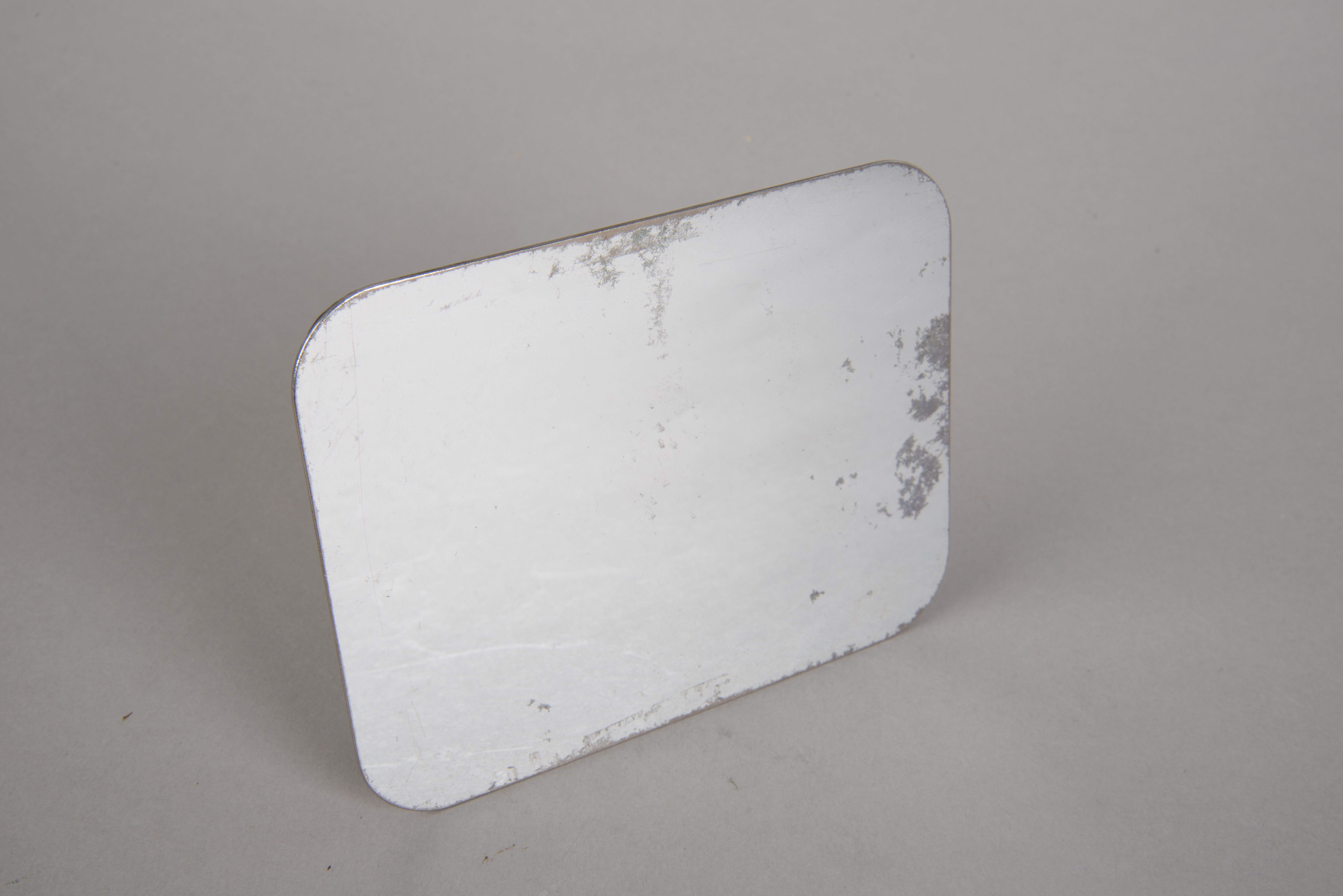
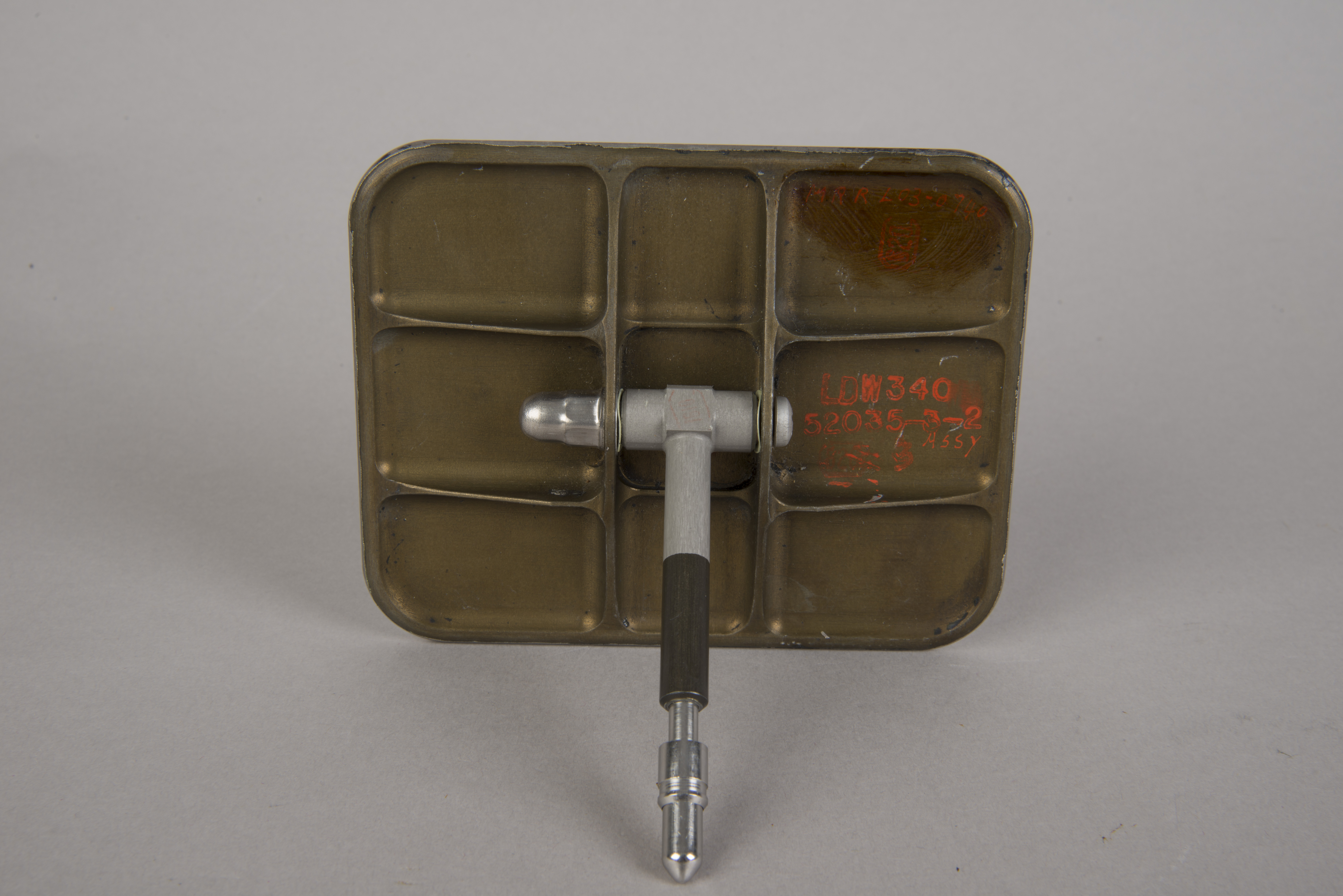
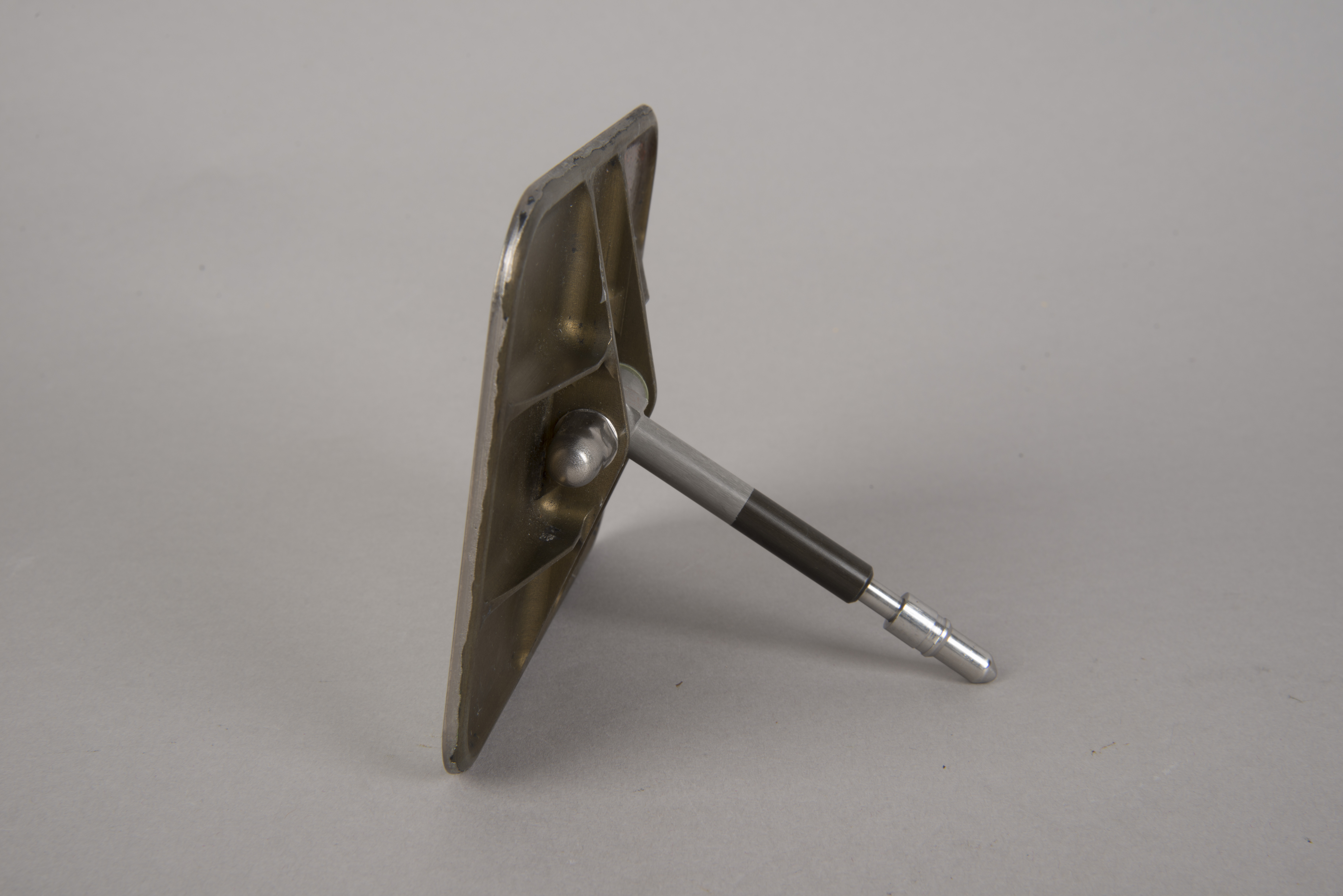
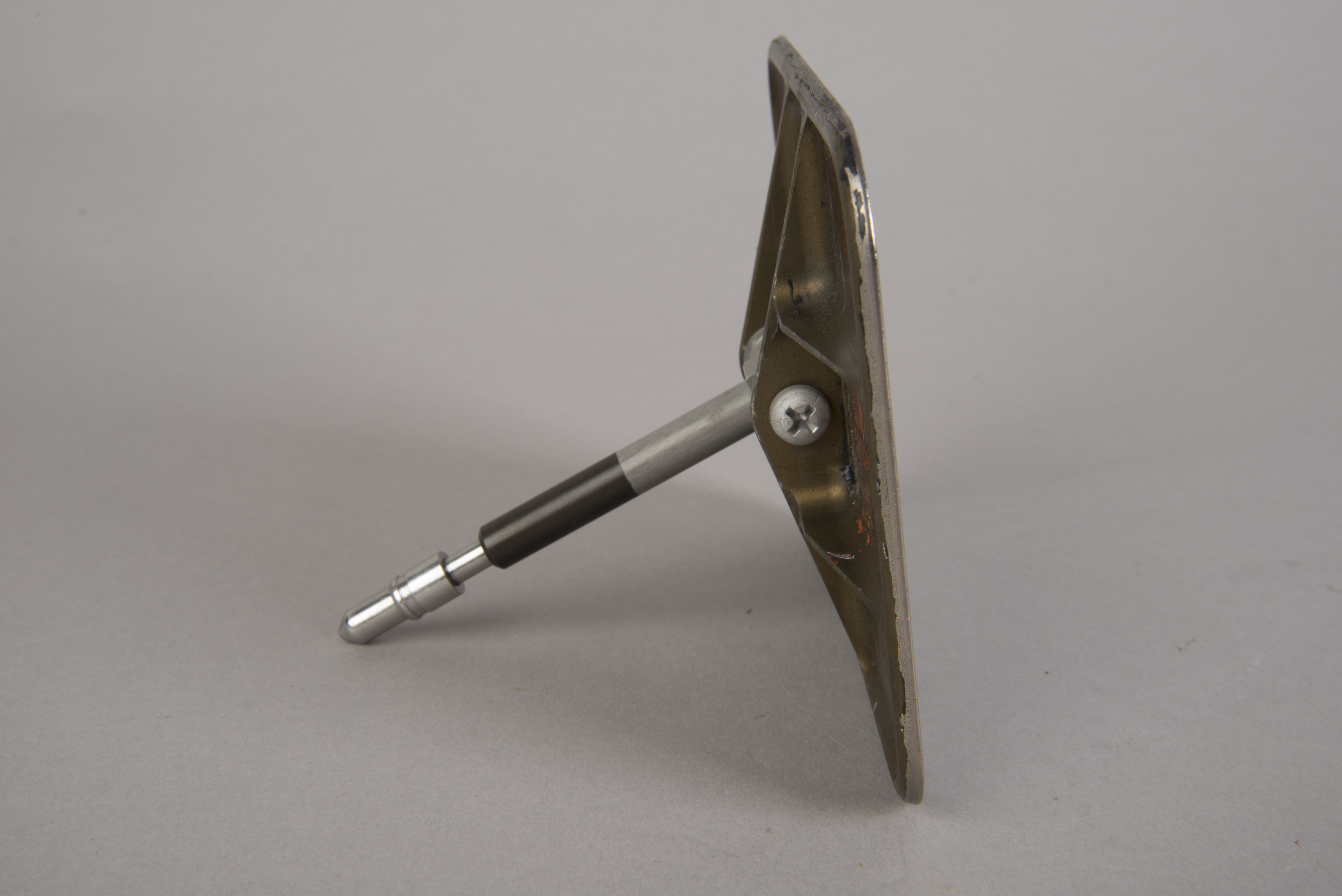
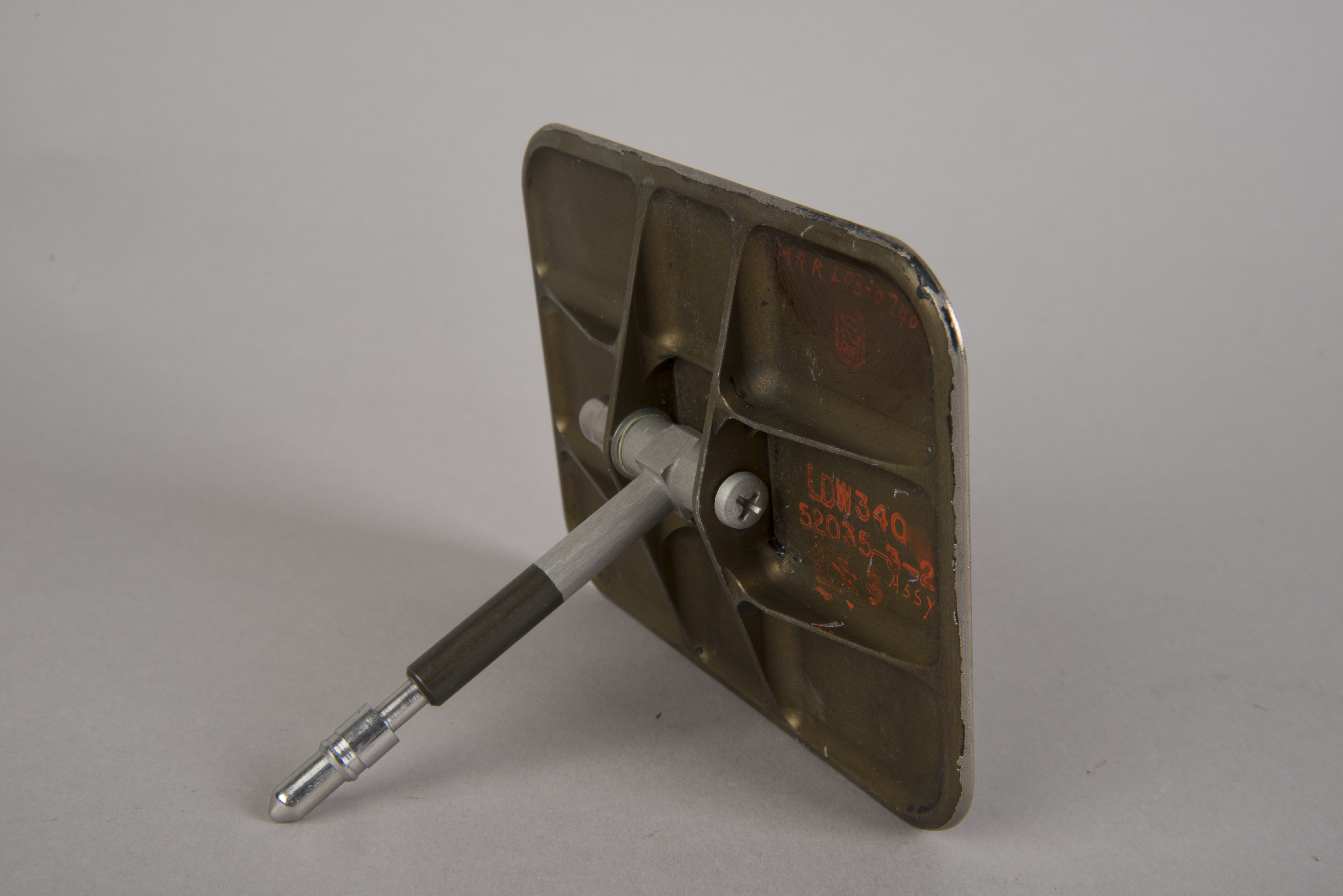
Mirror (Metal)

| Detail from January photo
69-H-134 showing a training mirror mounted over the left
side of the CDR window in a LM simulator. During
the flight out from Earth, the mirror was stowed as indicated
in the RHSSC under the panels to the right of his flight
station. (Click on the image for the full photo.) |
| The mirror was positioned to give the CDR a
view of the COAS when the latter was mounted in the
Rendezvous window during approach and docking. Without the
mirror he would have had to lean back a long way. |
Lotzmann photos
| MIrror back and mounting
hardware (DSC06928) Additional images: DSC06927, mirror back; DSC06932, side view; DSC06933, opposite side view. (Click on the image for a larger version) |
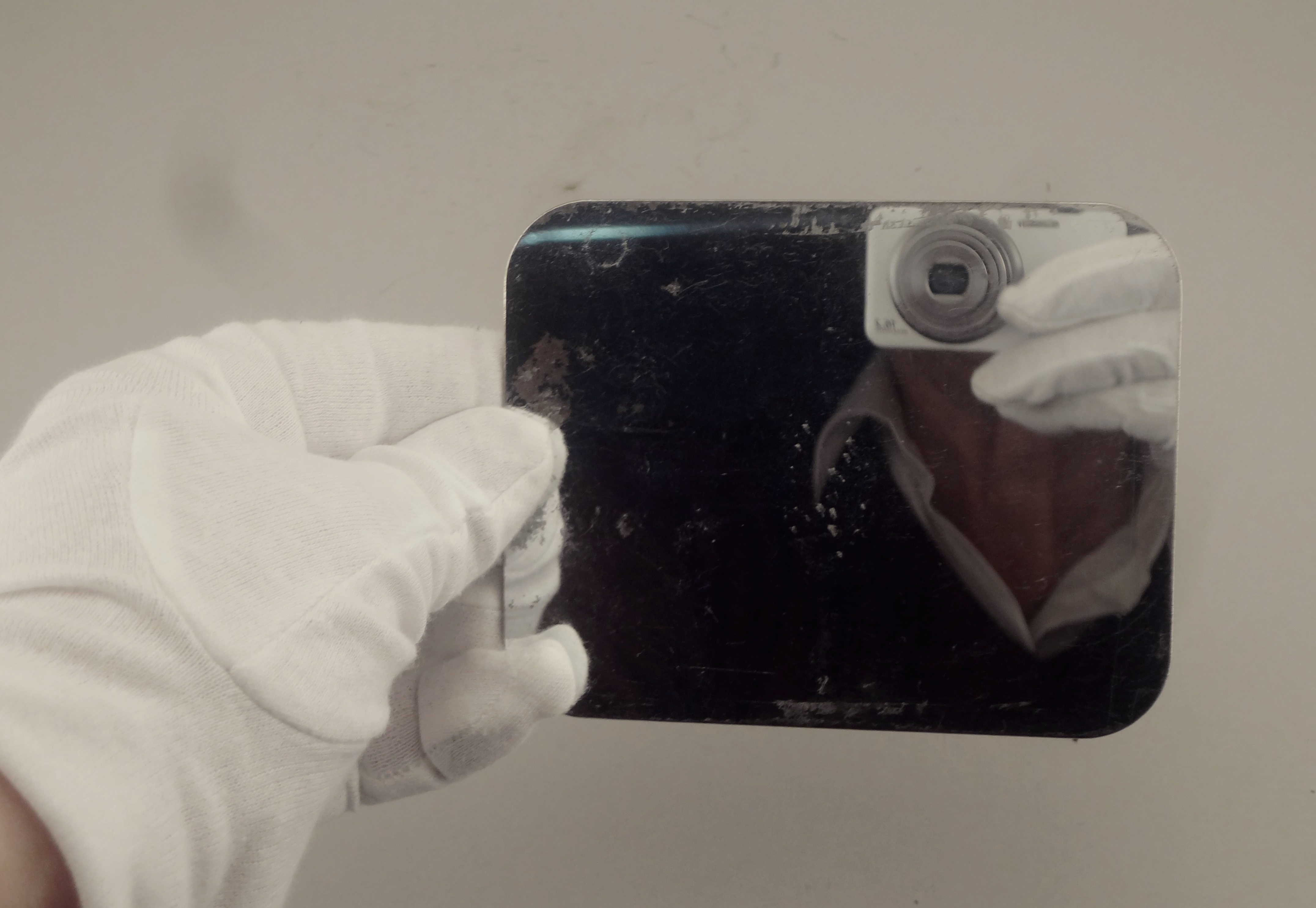
| Mirror front, with
reflection of the photographer (DSC06931). Additional images: DSC06929, mirror angled down; DSC06930. (Click on the image for a larger version) |
NASM Conservation Photographs
 |
 |
 |
 |
 |
 |
Return to Collection Image
Return to Apollo 11 Lunar Surface Journal
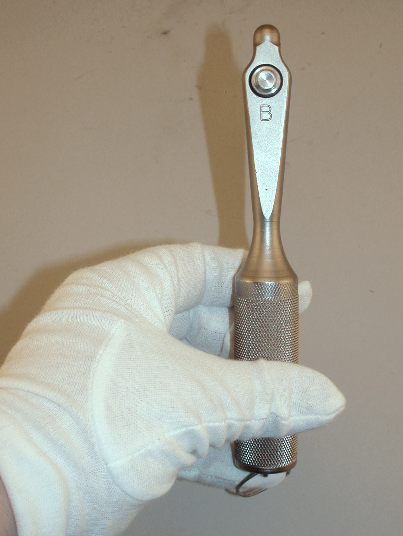
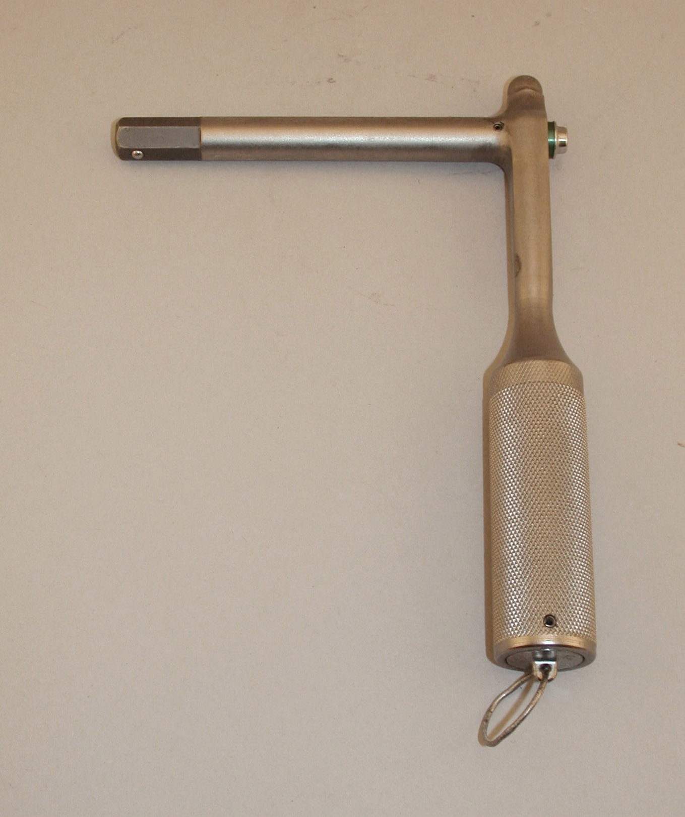
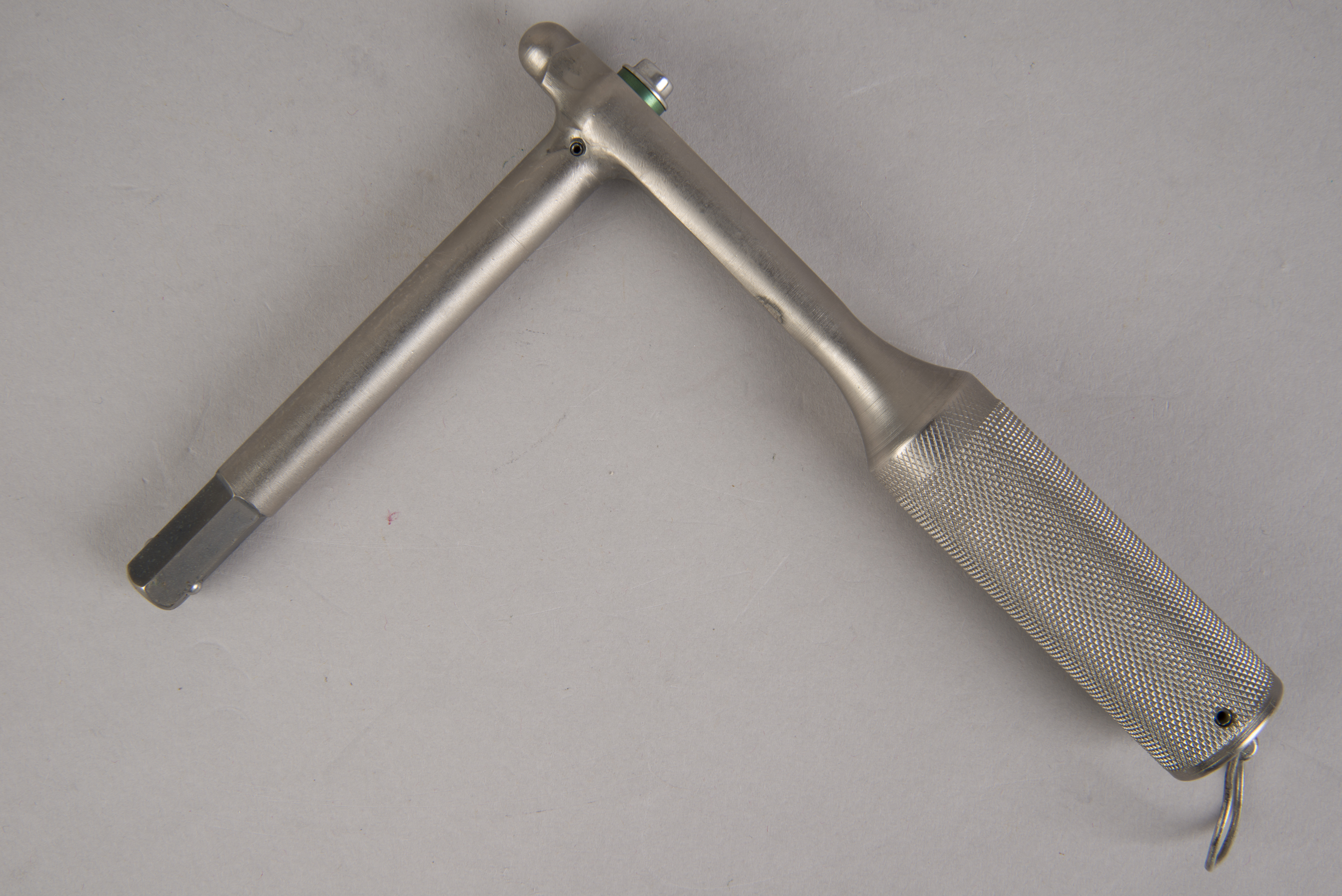
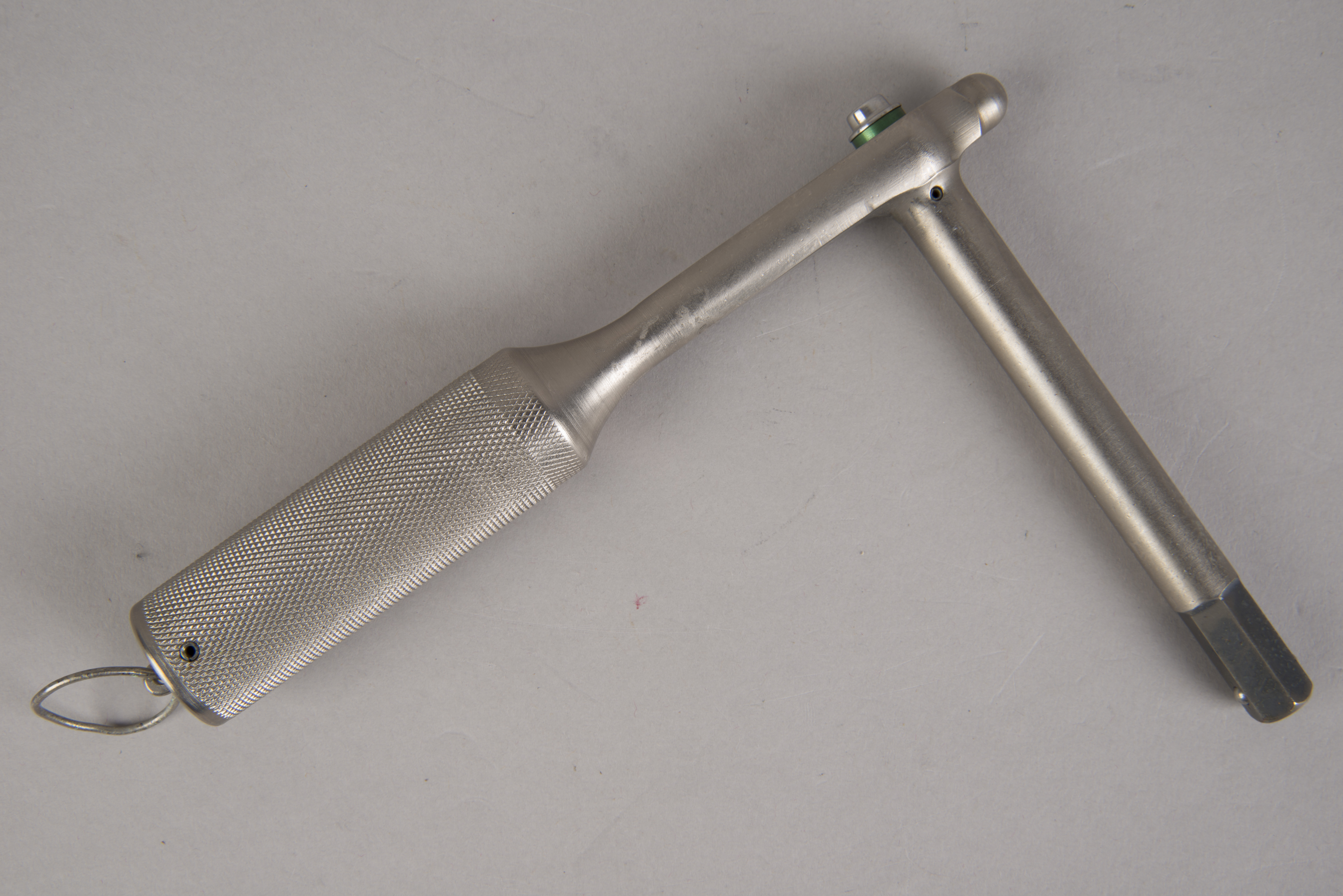
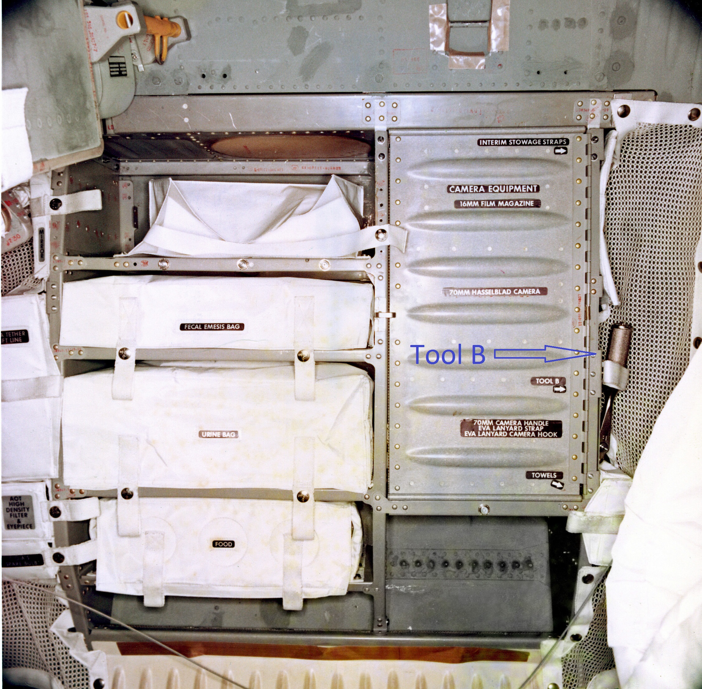
Emergency Wrench - Tool B
Lotzmann photos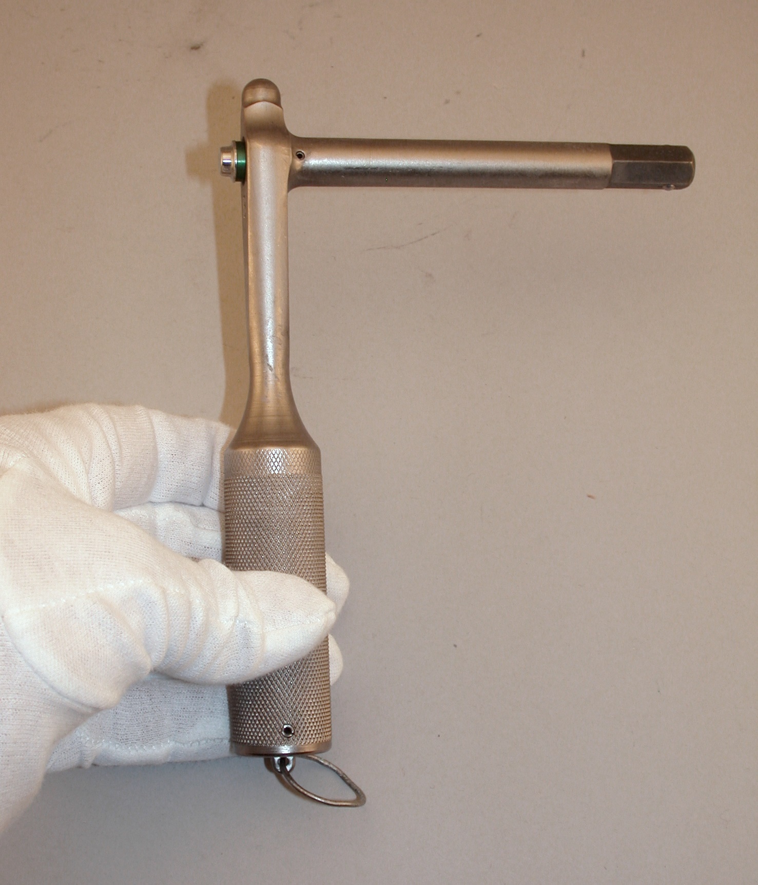 |
 |
 |
| (Click on the images for
larger versions.) |
NASM Conservation Photographs
 |
 |
| (Click on the images for
larger versions.) |
| From page 166 in Scott Sullivan's Virtual
LM, we have "Tool B (emergency wrench) was a
modified Allen-head L-wrench. It was 6.25 inches long and
had a 4.25-inch long drive shaft with a 7/16-inch
drive. The wrench could apply a torque of 4175
inch-pounds; it had a ball-lock device to lock the head of
the drive shaft. The wrench was used as a
contingency for use with the docking probe and drogue, and
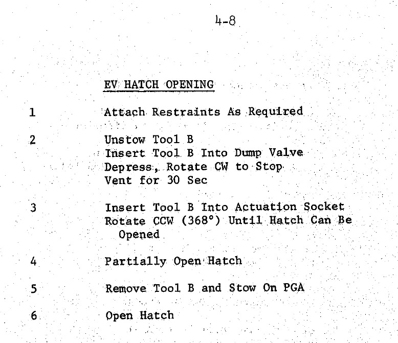
for opening the Command Module's hatch from the outside." In addition, it could be used to open a recalcitrant LM forward hatch prior to a Contingency Transfer of the LM crew to the Command Module if a docking problem precluded a normal transfer via the overhead hatch. The following comes from Section 4, ORBITAL CONTINGENCY EVA PROCEDURES, in Apollo 11 Final EVA Procedures: |
