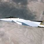


F-15 Flight Research Facility
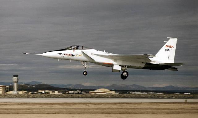
Flight research carried out by NASA with a highly modified F-15 aircraft demonstrated and evaluated advanced integrated flight and propulsion control system technologies that will help make next-generation aircraft more maneuverable, more fuel efficient, and safer to fly.
The NASA F-15 was the first aircraft to demonstrate a fully integrated inlet-engine-flight control system, a self-repairing flight control system, and a propulsion-only flight control system.
Background
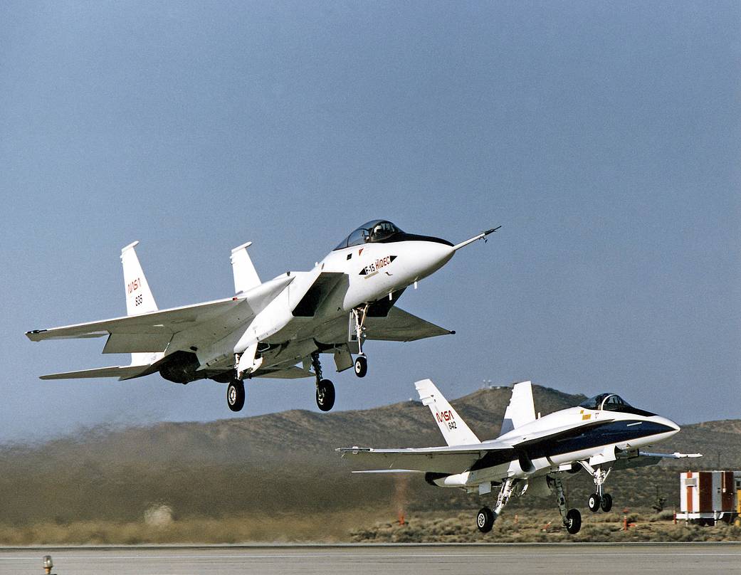
NASA F-15 TN (tail number) 835 was a unique one-of-a-kind aircraft called the F-15 Flight Research Facility. It was highly instrumented and equipped with an integrated digital electronic flight control system. It could be flown over a broad flight envelope to carry out complex and sophisticated research projects.
It was used, among other things, to develop the ADECS (Adaptive Engine Control System), SRFCS (Self-Repairing Flight Control System), PSC (Performance Seeking Control), and PCA (Propulsion Controlled Aircraft) system.
NASA obtained the F-15, an “A” model, from the U.S. Air Force on Jan. 5, 1976, and used it for more than 25 advanced research projects involving aerodynamics, performance, propulsion control, control integration, instrumentation development, human factors, and flight test techniques. Among these projects was one in which it served as a testbed to evaluate aerodynamic pressures on Space Shuttle thermal protection tiles at specific altitudes and speeds.
Highly Integrated Digital Electronic Control
The system that was developed on the F-15 to investigate and demonstrate methods of obtaining optimum aircraft performance was called HIDEC (Highly Integrated Digital Electronic Control).
The major elements of HIDEC were a DEFCS (Digital Electronic Flight Control System), a DEEC (Digital Electronic Engine Control), an on-board, general purpose computer, and an integrated architecture to allow all components to “talk to each other.”
Unlike standard F-15s, which have a mechanical and an analog electronic flight control system, the F-15 HIDEC also had a dual-channel, fail-safe digital flight control system that could be programmed in such high-order computer languages as Pascal, Ada, and FORTRAN. It was linked to the H009 and Military Standard 1553B data buses, which tied all other electronic systems together.
Adaptive Engine Control System
The ADECS (Adaptive Engine Control System) traded excess engine stall margin for improved performance. This was achieved through the integrated and computerized flight and engine control systems. The engine stall margin – the amount that engine operating pressures must be reduced to provide a margin of safety against an engine stall from excessive pressure – was continually monitored and adjusted by the integrated system, based on the flight profile and real-time performance needs.
Using this information, ADECS freed up engine performance that would otherwise be held in reserve to meet the stall margin requirement. Improved engine performance obtained through ADECS could take the form of increased thrust, reduced fuel usage, or lower engine operating temperatures because peak thrust was not always needed. Initial ADECS engineering work began in 1983. Research and demonstration flights with the ADECS system, which began in 1986, displayed increases in engine thrust of from 8% to 10.5% (depending on altitude), and up to 16% lower fuel consumption at 30,000 feet and constant thrust.
The increased engine thrust observed with ADECS improved the aircraft’s rate of climb 14% at 40,000 feet, and its time to climb from 10,000 feet to 40,000 feet was reduced 13% at an airspeed of 350 knots (15% at 250 knots). Increases of 5% to 24% in acceleration were also experienced at intermediate and maximum power settings, depending upon altitude. Overall, engine performance improvements (rate of climb and specific excess power) were in the range of 10% to 25% at maximum after-burning power.
No stalls were encountered during even aggressive maneuvering, although intentional stalls were induced to validate ADECS methodology.
Self-Repairing and Self-Diagnostic Flight Control System
During late 1989 and early 1990, the F-15 research aircraft investigated what could become a major breakthrough in airborne flight control capability. It was the first aircraft to demonstrate a SRFCS (Self-Repairing Flight Control System).
The program, sponsored by the U.S. Air Force, demonstrated the ability of a flight control system to identify the failure of a control surface and reconfigure commands to other control devices such as ailerons, rudders, elevators, and flaps to continue the aircraft’s mission or allow it to be landed safely.
As an example, if an aileron on an aircraft was damaged or failed in flight, the SRFCS immediately diagnosed the failure and determined how the remaining flight control surfaces could be repositioned to compensate for the damaged or inoperable control surface.
A display in the cockpit also informed the pilot of the control surface reconfiguration, and information displayed by the SRFCS showed the pilot what operational limitations he or she had to observe as a result of the damaged or failed component. These limitations reduced “G” loading (acceleration expressed in relation to the force of gravity), reduced angle-of-attack maneuvering, or reduced air speed and altitude margins.
The SRFCS also had the capability of identifying failures in electrical, hydraulic, and mechanical systems. When a failure in a normal flight control system occurred, ground maintenance diagnostic tests had to be conducted to identify the origin of the failure so that appropriate corrective actions could be taken. Ground maintenance crews often spend up to 60% of their time attempting to duplicate flight failures and correcting them. In many cases, the failure cannot be identified on the ground because actual flight conditions cannot be duplicated. This can be costly and time-consuming. System malfunctions on an aircraft with a SRFCS can be identified and isolated at the time they occur and then repaired as soon as the aircraft is on the ground.
Among the participants in the SRFCS research program, along with NASA Dryden, were the Air Force Wright Research and Development Center, Wright-Patterson Air Force Base, Ohio; McDonnell Aircraft Co., St. Louis, Missouri; and General Electric Aircraft Control Systems Division, Binghamton, New York.
While the SRFCS was limited to failures of control surfaces, researchers at Dryden also wanted to identify failures involving the basic stability of the aircraft. They subsequently began looking into neural networks in conjunction with researchers from NASA’s Ames Research Center. In 1999 they began flight research with neural networks on another F-15, which had been specifically designed with computers that could handle such identification schemes. Known as the ACTIVE (Advanced Control Technology for Integrated Vehicles), this F-15 served as a test bed to identify failures in the basic stability of the aircraft and eventually correct for them.
Performance Seeking Control
Research flights with the F-15 HIDEC began in the summer of 1990 on a program to optimize total aircraft engine performance during steady-state engine operation. The project was called PSC (Performance Seeking Control). Previous modes used on the HIDEC aircraft employed stored schedules of optimum engine pressure ratios for an average engine on a normal day. Using digital flight control, inlet control, and engine control systems, PSC employed integrated control laws to assure that peak engine and maneuvering performance was available to the pilot at all times, regardless of the mission or immediate needs.
PSC used highly advanced techniques to identify the condition of the engine components and optimize the overall system for best efficiency on the actual engine and flight conditions the pilot was encountering on a given day. Among the functions of PSC were reduction of fuel usage at cruise conditions; maximization of excess thrust during accelerations and climbs; and extending of engine life by reducing the fan turbine inlet temperature. PSC also included developing methods within the digital engine control system to detect degradation of components. This type of information, coupled with normal preventative maintenance, could help assure fail-safe propulsion systems in high performance aircraft of the future.
The PSC system is applicable to a wide variety of aircraft. For example, the engine manufacturer has used the self-tuning onboard engine model in its advanced engine controllers, including those on the F119 engine used on the F-22 aircraft. Other aspects of HIDEC technology have found application in the F100-PW-229 and other advanced engines, with the flight demonstration and evaluation done at NASA Dryden contributing to the rapid transition of the technology into operational use.
Propulsion Controlled Aircraft System
Several accidents in which part or all of an aircraft’s flight control system was lost prompted Dryden engineers to establish a research project to investigate the capability of a PCA (propulsion controlled aircraft), using only engine thrust for flight control. The NASA F-15 was modified to serve as the first-ever aircraft to intentionally demonstrate this PCA capability.
Initial flight studies with the pilot manually controlling the throttles and all F-15 flight controls locked showed that it was possible to maintain gross control. Altitude could be maintained within a few hundred feet using both throttles together. To climb, thrust would be added; to descend, thrust would be reduced. Heading could be controlled to within a few degrees, using differential throttle to generate yaw, which resulted in roll.
These initial flights also showed there was not enough precise flight control capability to land on a runway. This was due to the small control forces and moments of engine thrust, difficulty in controlling the airplane’s shallow dive and climb motion, and difficulty in compensating for the lag in engine response. Simulation studies at Dryden and at McDonnell Douglas duplicated the flight results. Control research and simulation studies also established the feasibility of using feedback of parameters such as flightpath angle, pitch rate, bank angle, roll rate, and yaw rate to augment the throttle control capability and to stabilize the aircraft.
The NASA F-15 was an ideal testbed for this research. It incorporated digital engine controls and digital flight controls, and it had a general purpose computer and data bus architecture to permit these digital systems to communicate with each other. There was also a cockpit computer panel for the pilot to make control system inputs so as to select options and vary system gains.
The only equipment added to the aircraft was a control panel containing two thumbwheels, one for the pilot’s flight path command, and the other for bank angle command. All of the needed sensors and actuators were available from previous integrated flight/propulsion control research. Control computations were performed in the research computer. All control parameters were recorded on the data system and telemetered to the ground. Tests of the PCA with the F-15 occurred at speeds of 150 knots with the flaps down and at 170 to 190 knots with the flaps up. Initial flights tested the “up and away” control capability, with landing approaches down to less than 10 feet above the ground.
Flight tests of PCA by Dryden with the F-15 concluded with a successful landing on April 21, 1993, using only engine power to turn, climb, and descend. A successful follow-on program with an MD-11 transport aircraft conclusively demonstrated the success of the technology in 1995. Dryden worked together with NASA’s Ames Research Center on simulations for PCA and later versions of the technology called PCA Lite and PCA Ultralite that expanded the number of airplanes that could use the technology and also made it less expensive to install.
Specifications
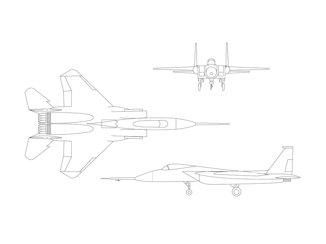
- McDonnell Aircraft Co., McDonnell Douglas Corporation, St. Louis, MO (now part of Boeing), designed the F-15 as a single-seat, twin-engine air superiority fighter. The first flight of the F-15 was in 1972.
- Two Pratt & Whitney F100-PW-100 or -220 engines normally power the F-15, depending on the aircraft model. The NASA F-15 was equipped with advanced versions of the F100, the F100 EMD (engine model derivative). The aircraft was capable of flying more than twice the speed of sound.
- The F-15 is 63.75 feet long and has a wingspan of 42.83 feet. The NASA F-15 was extensively modified for research activities and did not carry any armament.
Sources
- Frank W. Burcham, Jr., Ronald J. Ray, Timothy R. Conners, and Kevin R. Walsh, “Propulsion Flight Research at NASA Dryden from 1967 to 1997.” (Edwards, CA: NASA TP-1998-206554, 1998).
- James F. Stewart, “Integrated Flight Propulsion Control Research Results Using the NASA F-15 HIDEC Flight Research Facility.” (Edwards, CA: NASA TM 4394, 1992).
- Telephonic Interview with Dr. James F. Stewart, May 11, 1999.